
In a previous post this month I introduced my 4×4 matrix keypad. That keypad was designed to be directly interfaced to a microcontroller’s GPIO pins or alternatively to an IO expander chip like the PCF8574. That design, while working very well had the problem of requiring 8 GPIO pins to function correctly.
GPIO pins on a microcontroller can be considered very precious resources, and it should then be logical to assume that we should find a way to use these GPIO pins in a more conservative way, to allow us to interface more peripherals.
I solved this problem by integrating the keypad with an IO Expander on the same PCB. That will allow us to get away with using only 2 GPIO pins, and also open up the option of adding more keypads to the I2C bus, in the event that we need that many keys for a particular project.
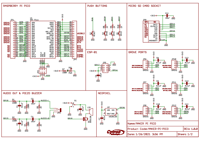
The Schematic
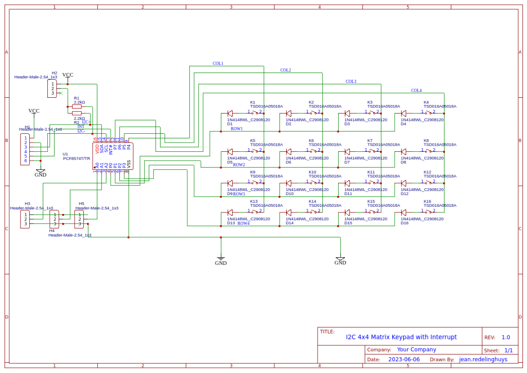
Looking closely at the schematic, we can see that it is exactly the same basic keypad circuit that I used in the initial design. The only difference is that in this design, I have integrated a PCF8574 directly onto the PCB.
Some additional features include selectable I2C Pullup resistors ( usually my microcontroller development boards already include those) that can be activated with a jumper when needed. There are also a set of address selection jumpers, making it possible to stack keypads together into a bigger keyboard if you require something like that. Note that, in this version of the hardware, I did not include headers for stacking.
The keypad can be powered by a DC power source of 3.3v to 5v.
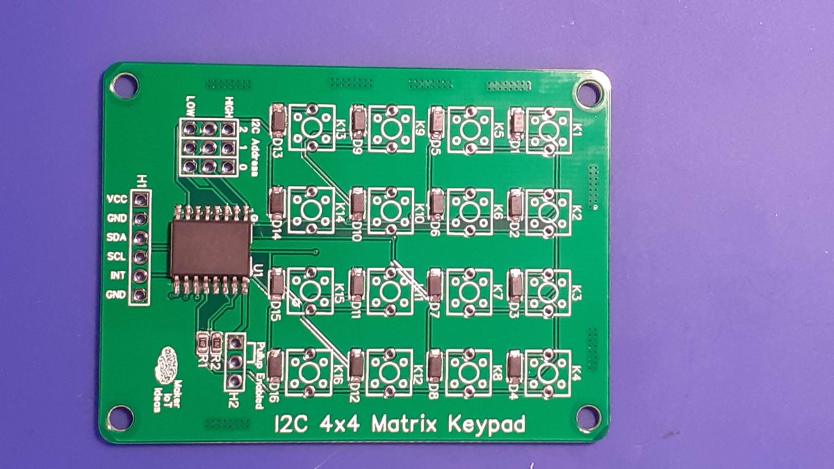
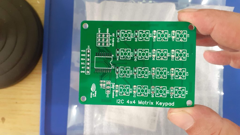
The PCB
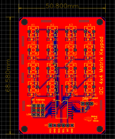
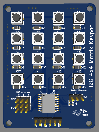
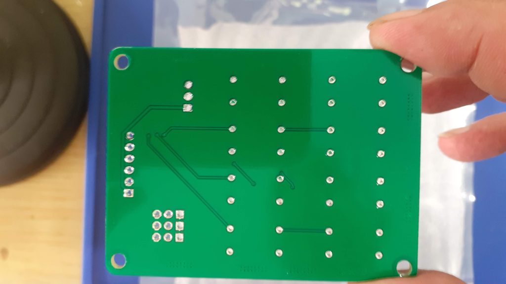
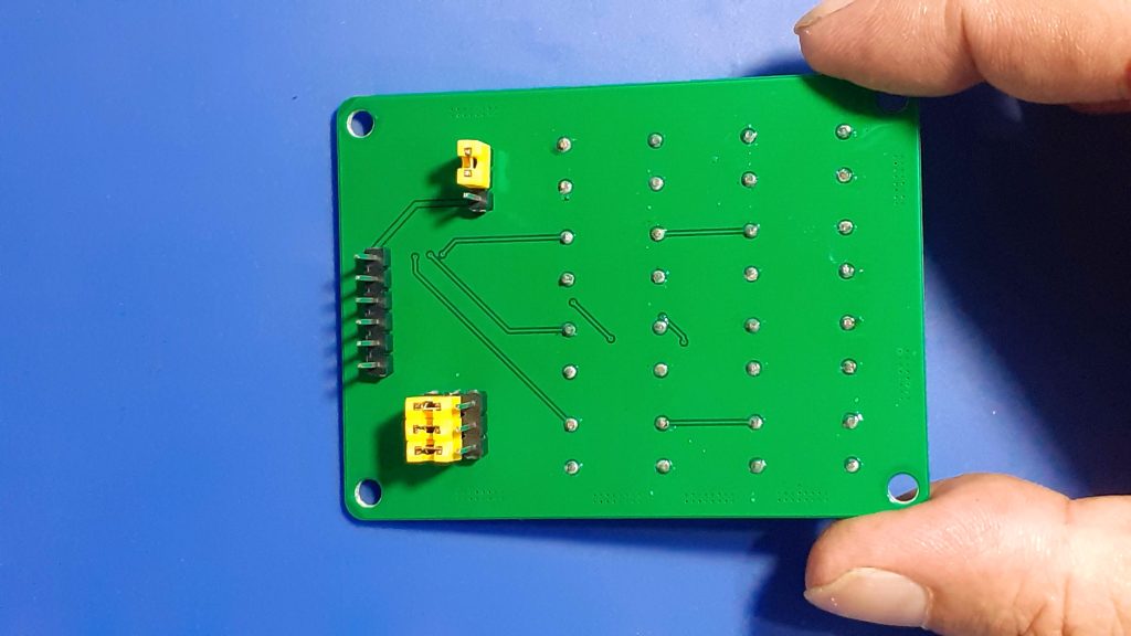
The PCB is a double-layer board of 68.8mm x 50.8mm. Male header pins provide access to the connections as well as address and pullup resistor jumpers. In my build, I have mounted these male headers on the back of the PCB. That makes it possible to mount the Keypad in an enclosure without having the jumpers “stick out” and get in the way.
Manufacturing
I choose PCBWay for my PCB manufacturing.
This month, PCBWay is also celebrating its 9th anniversary, and that means that there are quite a lot of very special offers available.
Why?
What makes them different from the rest?
PCBWay‘s business goal is to be the most professional PCB manufacturer for prototyping and low-volume production work in the world. With more than a decade in the business, they are committed to meeting the needs of their customers from different industries in terms of quality, delivery, cost-effectiveness and any other demanding requests. As one of the most experienced PCB manufacturers and SMT Assemblers in China, they pride themselves to be our (the Makers) best business partners, as well as good friends in every aspect of our PCB manufacturing needs. They strive to make our R&D work easy and hassle-free.
How do they do that?
PCBWay is NOT a broker. That means that they do all manufacturing and assembly themselves, cutting out all the middlemen, and saving us money.
PCBWay’s online quoting system gives a very detailed and accurate picture of all costs upfront, including components and assembly costs. This saves a lot of time and hassle.
PCBWay gives you one-on-one customer support, that answers you in 5 minutes ( from the Website chat ), or by email within a few hours ( from your personal account manager). Issues are really resolved very quickly, not that there are many anyway, but, as we are all human, it is nice to know that when a gremlin rears its head, you have someone to talk to that will do his/her best to resolve your issue as soon as possible.
Find out more here


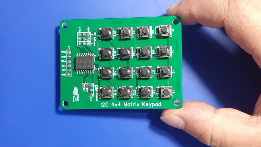
Assembly
The assembly of this PCB was quite easy and quick. A stencil is not required. All SMD components are 0805 or bigger. It would thus be quite easy to solder them all by hand with a fine-tipped soldering iron.
I have however used soldering paste and hot air to reflow the components, as it is the fastest, in my opinion, and definitely looks neater than hand soldering.
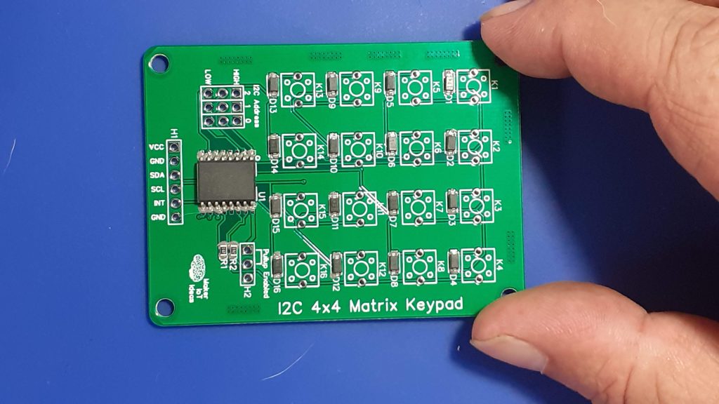

The board is now ready to solder the switches and header pins in place. As already mentioned above, I chose to assemble the headers on the back of the PCB to prevent them from interfering with any enclosure that I may later use with the keypad.
Testing and Coding
Testing the keypad consisted of a few steps, the first of which was ensuring that there were no short circuits, as well as that all the momentary switches worked.
This was done with a multimeter in continuity as well as diode mode, with probes alternatively on each column and row in turn, while pressing the buttons.
The next stage was testing the I2C IO Expander. This was done with a simple I2C Scanning sketch on an Arduino Uno. It did not do a lot, but, I could see that the PCF8574 is responding to its address and that the pullup resistors work when enabled. This test was repeated with my own ESP8266 and ESP32 boards, this time with pullup resistors disabled, as these boards already have them onboard.
Coding came next, and it was another case of perspectives. It seems like all commercial keypads do not have diodes. This affects the way that they work with a given library. It seems that software developers and hardware developers have different understandings of what a row and a column is.
This meant that, due to the fact that I have diodes on each switch, and the way that the library work – which pins are pulled high and which are set as inputs -, I had to swap around my rows and columns in the software to get everything to work. On a keypad with the diodes replaced with 0-ohm links, that was not needed.
A short test sketch follows below:
Note that with was run on an ESP8266-12E, therefore the Wire.begin() function was changed to Wire.begin(4,5); in order to use GPIO 4 and GPIO 5 for I2C
Another point to note is that the keypad Layout will seem strange. Remember that this is due to the diodes in series on each switch. That forces us to swap around the Rows and the Columns in the software, resulting in a mirrored and rotated left representation of the keypad. It looks funny, but believe me, it actually still works perfectly.
#include <Wire.h>
#include "Keypad.h"
#include <Keypad_I2C.h>

const byte n_rows = 4;
const byte n_cols = 4;

char keys[n_rows][n_cols] = {
    {'1', '4', '7', '*'},
    {'2', '5', '8', '0'},
    {'3', '6', '9', '#'},
    {'A', 'B', 'C', 'D'}};

byte rowPins[n_rows] = {4, 5, 6, 7};
byte colPins[n_cols] = {0, 1, 2, 3};

Keypad_I2C myKeypad = Keypad_I2C(makeKeymap(keys), rowPins, colPins, n_rows, n_cols, 0x20);

String swOnState(KeyState kpadState)
{
    switch (kpadState)
    {
    case IDLE:
        return "IDLE";
        break;
    case PRESSED:
        return "PRESSED";
        break;
    case HOLD:
        return "HOLD";
        break;
    case RELEASED:
        return "RELEASED";
        break;
    } // end switch-case
    return "";
} // end switch on state function

void setup()
{
    // This will be called by App.setup()
    Serial.begin(115200);
    while (!Serial)
    { /*wait*/
    }
    Serial.println("Press any key...");
    Wire.begin(4,5);
    myKeypad.begin(makeKeymap(keys));
}

char myKeyp = NO_KEY;
KeyState myKSp = IDLE;
auto myHold = false;

void loop()
{

    char myKey = myKeypad.getKey();
    KeyState myKS = myKeypad.getState();

    if (myKSp != myKS && myKS != IDLE)
    {
        Serial.print("myKS: ");
        Serial.println(swOnState(myKS));
        myKSp = myKS;
        if (myKey != NULL)
            myKeyp = myKey;
        String r;
        r = myKeyp;
        Serial.println("myKey: " + String(r));
        if (myKS == HOLD)
            myHold = true;
        if (myKS == RELEASED)
        {
            if (myHold)
                r = r + "+";
            Serial.println(r.c_str());
            myHold = false;
        }
        Serial.println(swOnState(myKS));
        myKey == NULL;
        myKS = IDLE;
    }
}
Conclusion
This project once again delivered what I set out to achieve. It has some quirks, but nothing serious. Everything works as expected, both in the Arduino IDE/platform IO realm, as well as in ESPHome. It is worth noting that in ESPHome, we do not need to swap the rows and columns to use the Keypad component. Do remember to leave the has_diodes flag to false though…


