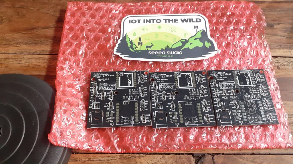
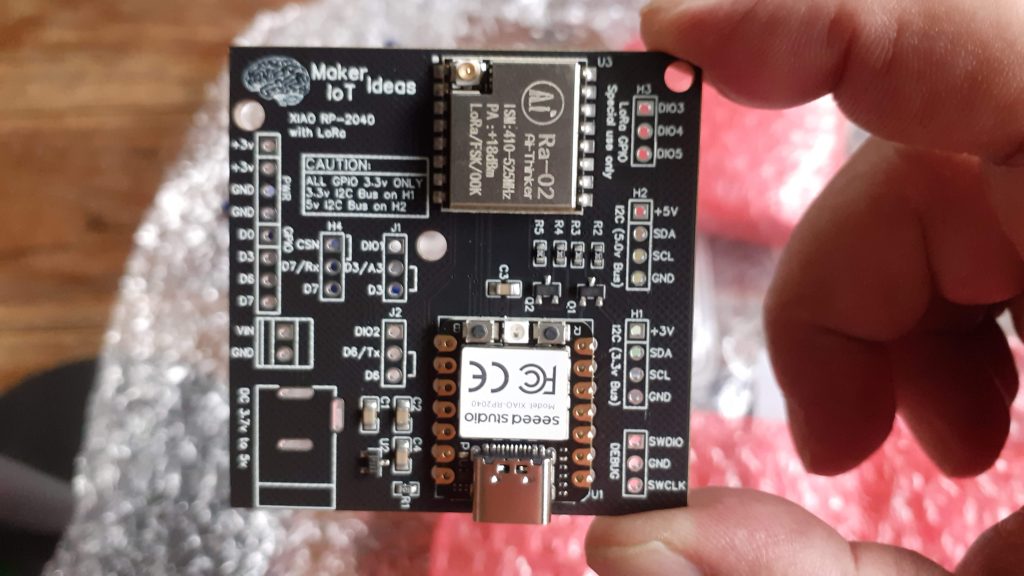
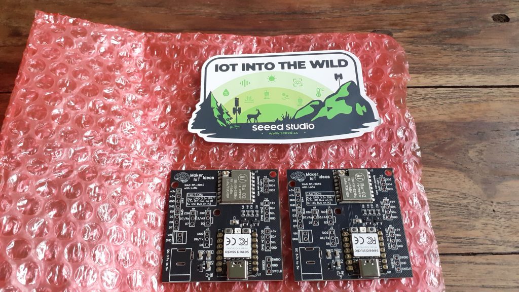
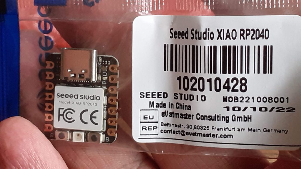
In this post, we will look at a versatile easy-to-use XIAO RP2040 LoRa Fusion. The SEEED Studio Xiao RP2040 should, by now, no longer be a stranger to any of us makers and electronics enthusiasts. At its heart, it contains the same RP2040 processor that is used on the Raspberry Pi Pico.
What makes, the Xiao RP2040, special is its size, only 20.00mm x 17.5mm, as well as the carefully curated combination of GPIO pins, single-sided board construction and castellated pads to make incorporating it directly into a design an absolute pleasure.
Features
- Powerful MCU: Dual-core ARM Cortex M0+ processor, flexible clock running up to 133 MHz
- Rich on-chip resources: 264KB of SRAM, and 2MB of onboard Flash memory
- Flexible compatibility: Support Micropython/Arduino/CircuitPython
- Easy project operation: Breadboard-friendly & SMD design, no components on the back
- Small size: As small as a thumb(20×17.5mm) for wearable devices and small projects.
- Multiple interfaces: 11 digital pins, 4 analog pins, 11 PWM Pins,1 I2C interface, 1 UART interface, 1 SPI interface and 1 SWD Bonding pad interface.
Specifications
| Item | Value |
|---|---|
| CPU | Dual-core ARM Cortex M0+ processor up to 133MHz |
| Flash Memory | 2MB |
| SRAM | 264KB |
| Digital I/O Pins | 11 |
| Analog I/O Pins | 4 |
| PWM Pins | 11 |
| I2C interface | 1 |
| SPI interface | 1 |
| UART interface | 1 |
| Power supply and downloading interface | Type-C |
| Power | 3.3V/5V DC |
| Dimensions | 20×17.5×3.5mm |
The AI-Thinker RA-02 also need no introduction from me, as I have used it extensively in quite a few projects before.
With the worldwide chip shortage, building solutions around the easily available RP2040, and RA-02 makes perfect sense, as these two modules are also super cheap.
For this project, I have also decided to try out a fully factory-assembled PCB to compare quality, as well as the convenience of being able to focus on software without doing assembly first, not that I mind assembling my own boards though… More on that experience later…
What were my intentions with this project?
I had the following goals/needs:
1. A modern, easily obtainable processor, that is not only cheap but also energy efficient. The RP2040, in the form of the Xiao RP2040, fits that goal perfectly.
2. An as-small-as-possible footprint for the main processor, without having to resort to manually designing a Pi Pico derivative – The RP2040 chip is a bit tiny for my eyes
3. The minimum of external supporting components to make the design function
4. Flexible power options ( 3v or 5v )
As to my use intentions, I use quite a few LoRa devices for various different purposes, so adding another option seemed like a good idea.
In the current design, providing that the Arduino libraries stay compatible, the new design will support not only LoRa but also FSK and OOK, with all the advantages of those.
By changing the position of only 3 jumpers, I can also use the PCB for a general-use RP2040 development platform, or another RP2040 project.
Taking all of this into consideration, the device will thus be ideal for any remote sensor application, as well as using it on the bench-top for prototyping
What features are on the PCB?
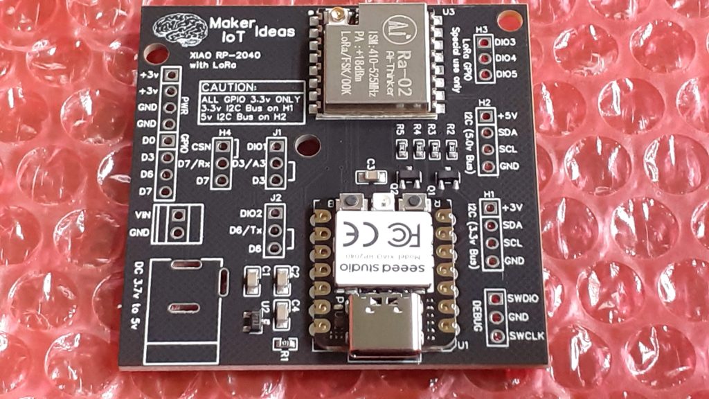
- All of the Xiao RP2040’s pins and pads are broken out onto the PCB, including the SWD port.
- The Xiao also has a user LED, and a NeoPixel on-board, which can easily be used for signal indication.
- Level shifted 5v I2C port, in addition to the standard 3.3v I2C, because all of our sensors are not always 3.3v compatible, and using external level shifters is not always so convenient.
- Access to the RA-02’s GPIOs (DIO1-DIO5) is provided, but most people won’t need to worry about these.
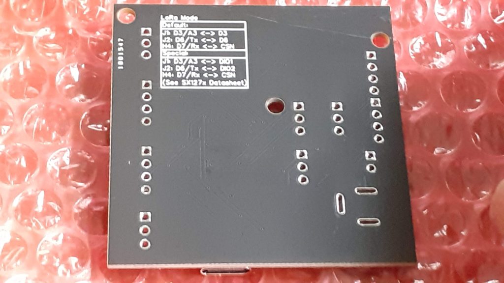
- Jumpers to connect some of the Xiao RP2040 GPIO to the special use GPIO on the RA-02, for example, GPIO1 and GPIO2, sometimes used with some of the more specialised LoRa libraries.
- Provision or powering the device via a dc barrel connector, or screw-terminal, as well as via the 3v input pins (make sure your supply has a capability of more than 300mA)
- A power management chip to reset the Xiao RP2040 when the supply voltage falls below 3.0v – To prevent unstable operation and possible lock-up.
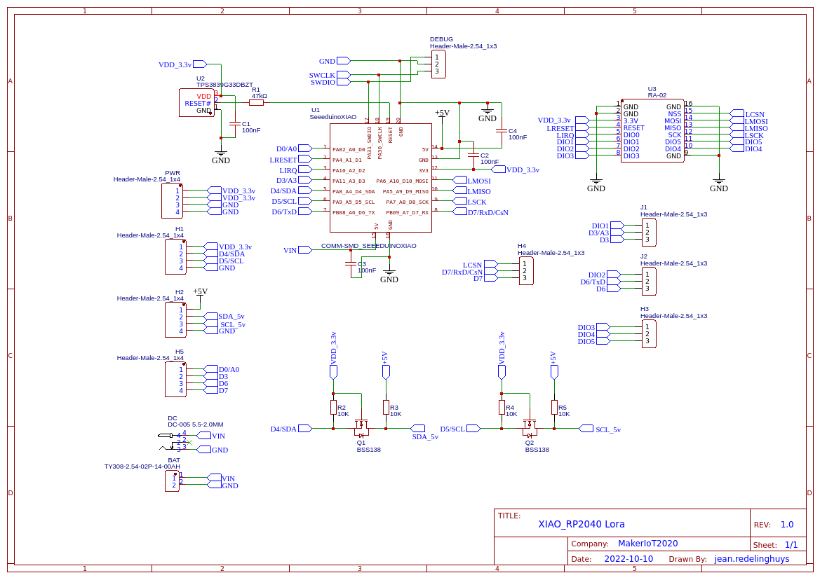
The Schematic
PCB Design and Rendered Images


Manufacturing and Assembly of the PCB
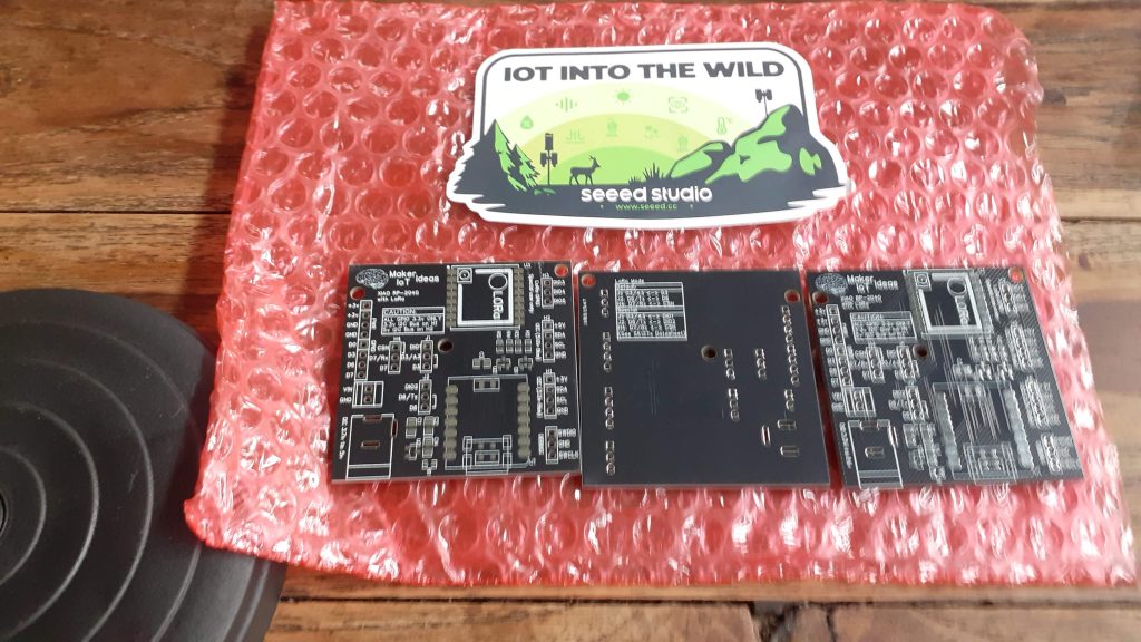
For this project, I have decided to try out SEEED STUDIO’s Fusion Service.
They are after all the manufacturers of the Xiao RP2040 Module that I used, so, when they contacted me a few weeks ago with an invite to try out their Fusion service, I decided to give it a go.
Seeed Fusion offers one-stop prototyping for PCB manufacture and PCB assembly services, and as a result, they produce superior quality PCBs and Fast Turnkey PCBA in as little as 7 working days. When you prototype with Seeed Fusion, they can definitely provide Free DFA and Free functional tests for you!
So, what was my experience like?
From a design point-of-view, nothing much changed, except that I had to spend a bit more time focusing on the BOM, as my usual go-to for components is LCSC. I, therefore, had to make a few small substitutions on some passive components to ensure that everything was in stock and available.
I also chose to only have the SMD components on the PCB factory assembled. Soldering a few header pins is no trouble anyway.
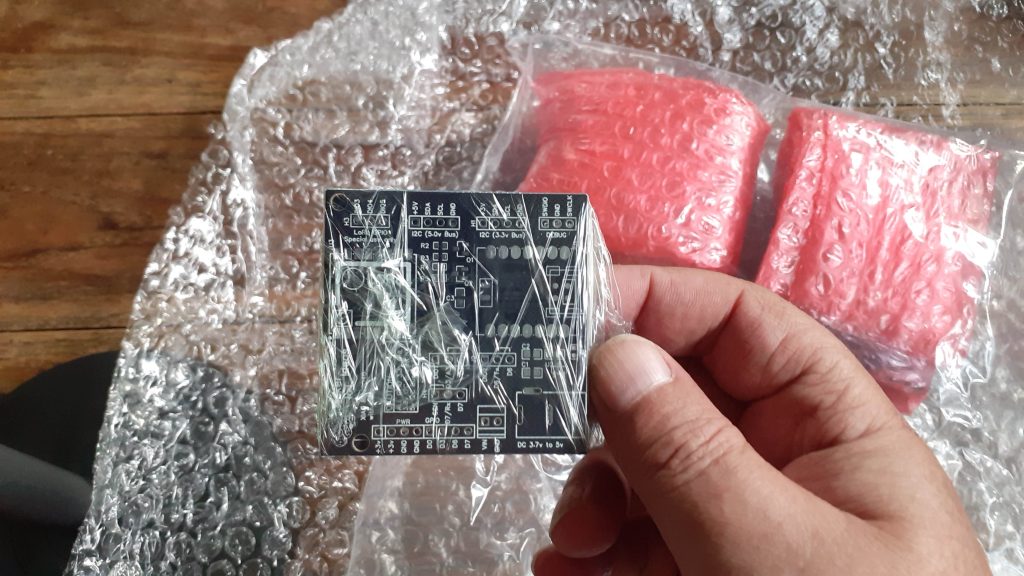
Manufacturing and shipping lead times were not too long, and I received the assembled boards in about 7 working days from the time of order.
Using the PCB
The Xiao RP2040 has great support for Micropython, CircuitPython as well as the Arduino IDE. There is an excellent article on getting started with the XIAO RP2040 available here , with sections on all three supported development languages and environments.
You can also try out some machine-learning projects with TinyML
As mentioned above, most of the 11 GPIO pins on the XIAO RP2040 were broken out to headers on the PCB, with the exception of those needed for dedicated control of the RA-02 LoRa Module ( D1, D2, D8, D9, D10). In addition to this, some other GPIO, like the I2C pins (D4 and D5) may be accessed on H1 (labelled as SCL/SDA) [3.3v logic] or alternatively on H2 (as SCL/SDA) [ note that this header is level converted to 5.0v ]
To accommodate some other special use features of the RA-02 LoRa Module, J1 and J2 can be jumpered in two positions to connect D3 to DIO1 on the RA-02, and D6 to DIO2 alternatively. Most people will however not need to do this.
When using the Hardware UART on the Xiao RP2040, the jumper at H4 needs to be set to D7/Rx->D7 in order to receive Data, and J2 should be in the default D6/Tx->D6 position


Testing the PCB with LoRa
In order to test the functionality, I have written a very simple sketch to test the communication between the PCB and another LoRa device, running a similar sketch…
#include <SPI.h>       // include libraries

#include <LoRa.h> // I used Sandeep Mistry’s LoRa Library, as it is easy to //use and understand


const int csPin = D7;     // LoRa radio chip select

const int resetPin = D1;    // LoRa radio reset

const int irqPin = D2;     // change for your board; must be a hardware //interrupt pin

byte msgCount = 0;      // count of outgoing messages

int interval = 2000;     // interval between sends

long lastSendTime = 0;    // time of last packet send

void setup() {
Serial.begin(115200); // initialize serial
while (!Serial);
Serial.println("LoRa Duplex - Set spreading factor");
// override the default CS, reset, and IRQ pins (optional)
LoRa.setPins(csPin, resetPin, irqPin); // set CS, reset, IRQ pin
if (!LoRa.begin(433E6)) { // initialize ratio at 433 MHz
Serial.println("LoRa init failed. Check your connections.");
while (true); // if failed, do nothing
}
LoRa.setSpreadingFactor(8); // ranges from 6-12,default 7 see API docs
Serial.println("LoRa init succeeded.");
}
void loop() {
if (millis() - lastSendTime > interval) {
String message = "Testing Xiao RP2040 - LoRa "; // send a message
message += msgCount;
sendMessage(message);
Serial.println("Sending " + message);
lastSendTime = millis(); // timestamp the message
interval = random(2000) + 1000; // 2-3 seconds
//msgCount++;
}
// parse for a packet, and call onReceive with the result:
onReceive(LoRa.parsePacket());
}
void sendMessage(String outgoing) {
LoRa.beginPacket(); // start packet
LoRa.print(outgoing); // add payload
LoRa.endPacket(); // finish packet and send it
msgCount++; // increment message ID
}
void onReceive(int packetSize) {
if (packetSize == 0) return; // if there's no packet, return
// read packet header bytes:
String incoming = "";
while (LoRa.available()) {
incoming += (char)LoRa.read();
}
Serial.println("Message: " + incoming);
Serial.println("RSSI: " + String(LoRa.packetRssi()));
Serial.println("Snr: " + String(LoRa.packetSnr()));
Serial.println();
}
Please note that the sketch uses callbacks on receiving messages.
In conclusion
This project was quite interesting, and I am very much impressed with the quality of the assembly done by SEEED Studio’s Fusion Service. The Xiao RP2040 is also a pleasure to work with, and I hope that with future iterations of this prototype, I may be able to produce an even more compact PCB, that will still pack some serious performance punches while being power efficient as well
