
As a followup to my recent ESP32-S in Arduino Form Factor device, I decided to also produce a similar circuit board for the ESP8266-12E. Although some people mostly consider these as obsolete, I still find them extremely useful for small projects, and thus use quite a lot of them.
With their lower total pin count and similar low cost to the bigger ESP32 modules, these do force you to get quite creative with the available pins, as well as how and what you can interface.

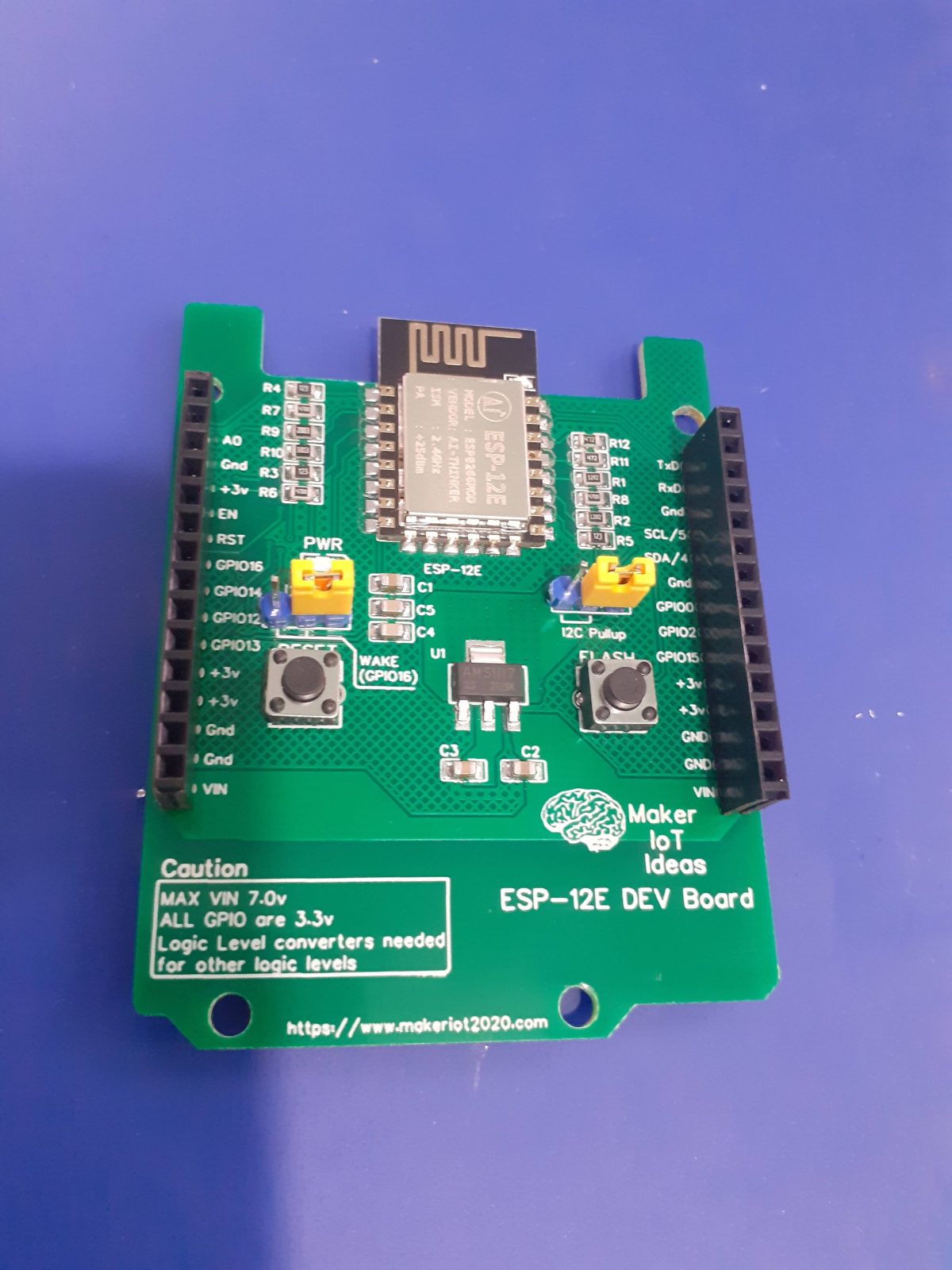
What is on the PCB?
For this design, I have once again tried to keep it very lean, including the absolute bare minimum supporting components needed for correct operation.
This includes pull-up and pull-down resistors on the various strapping pins, as well as some decoupling capacitors.
I also did not include a USB-to-Serial converter circuit, as these are used only once or twice, and also consume power while not being needed all the time.
As most of my devices are uploaded OTA anyway, an external stand-alone USB-to-Serial adapter is perfect to upload the initial firmware.
Jumpers to control the onboard I2C pullup-resistors, as well as the Wake-up-from-deep-sleep function on GPIO16 were also added, in addition to the Reset and Flash push-buttons to place the device into initial programming mode.
A 3.3v LDO regulator was also added, for convenience mostly, when powering the device from a bench power supply unit. The recommended voltage for this LDO would in my opinion be 7v Dc, although the datasheet states it can be up to 15v DC… In my opinion, that stresses the component a bit much though, as most of that excessive voltage is dissipated as heat.
PCB Layout – Blank board, front and back


To try and minimise heat-related issues with the LDO regulator, I have incorporated an on-PCB heatsink for the LDO regulator, which is via-stiched together on both sides of the PCB. This type of heatsink seems to work quite well in many of my other designs, so I decided to use it here as well.
I have also made use of big copper pours on both sides of the PCB to ensure that there is a good ground plane, as well as make use of differential pairs for the routing of the UART and I2C tracks.
Schematic

PCB Design

Manufacturing
The PCB for this project has been manufactured at PCBWay.
Please consider supporting them if you would like your own copy of this PCB, or if you have any PCB of your own that you need to have manufactured.
You can get your own copy here

Some assembly pictures


Procedure to upload initial firmware
Due to the fact that this device does not have an onboard USB-to-UART (Serial) converter, it will be necessary to use an external device the first time that you upload firmware, or while you are using it on the bench if you do not want to use OTA…
The easiest way to do this, in my opinion, is the following:
1) Power the device from a bench power supply, set at 7V DC via the VIN and GND Pins, available on the bottom left and right of the device ( you can use either side, not both 🙂
2) Now connect your external USB-to-UART converter to the device, as follows:
UART Converter <-> ESP-12E Dev Board
Rx <- TxD
Tx -> RxD
Gnd — GnD
Do Not connect the power (VCC) from the USB-to-UART Converter!
Now start your Adruino IDE, or similar, and connect to the Serial monitor.
Press the reset button on the board, and watch for output in the serial monitor.
If you see output, at 115200 BPS, press end hold flash, and then press and let go of reset, while still holding the flash button.
Wait a few seconds, and then upload your sketch, remembering to manually reset the board after the upload has completed.
I would recommend that you upload the Arduino OTA sketch, from the examples, and modify it to connect to your local WiFi. That way, you will be able to upload all following sketches via your local Wifi, providing that you do not remove the OTA code from the sketch.