
These days, Makers have access to quite a few different microprocessors for use in their projects. Most of them can be found on development boards of some sort, but not all are in a convenient size. The reason for this is that most of these development boards were designed with a breadboard in mind, and then after your prototype is done, you are required to design a PCB and place the specific processor and its supporting components onto this custom PCB…

Many makers choose to skip this step, either choosing to keep the project on the breadboard, or place the entire development module onto a piece of stripboard or similar, and then place their supporting components and sensors around that.
This is where the SEEED XIAO is different. It comes in a thumb-nail-sized package and can be used on the breadboard or directly placed onto a PCB via either pin headers or if you want access to all of its features, SMD pads.

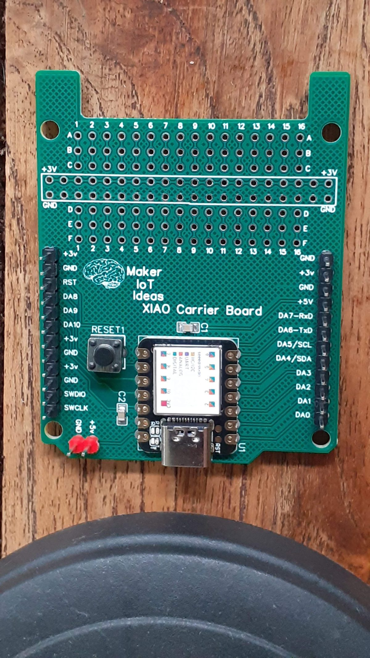
In this build, I decided to design a generic carrier board, that will accept most of the XIAO RP2040 or the XIAO SAMD21
I have also included a small prototype area on the PCB, so that Makers can easily transfer their existing XIAO projects onto a semi-custom PCB, without having to design their own.
I have also addressed a problem area, especially with the XIAO SAMD21, it has no onboard reset button, only two tiny pads, by including a reset button for ease of use.
The PCB is in Arduino Uno form factor, and also provides headers to power it from an external 5v DC supply. Please note that the prototyping area has a 3.3v power rail, – due to the fact that all of the XIAO GPIO are limited to 3.3v anyway -. This power rail is powered directly from the XIAO 3.3v output, and the current is limited as per the specifications of the XIAO module that you are using.
Hardware Specifications – SEEEDuino XIAO
Hardware specifications and comparison
| Processor | ESP32-C3 32-bit RISC-V @160MHz | SAMD21 M0+@48MHz | RP2040 Dual-core M0+@133Mhz | nRF52840 M4F@64MHz | nRF52840 M4F@64MHz |
| Wireless Connectivity | WiFi and Bluetooth 5 (LE) | N/A | N/A | Bluetooth 5.0/BLE/NFC | Bluetooth 5.0/BLE/NFC |
| Memory | 400KB SRAM, 4MB onboard Flash | 32KB SRAM 256KB FLASH | 264KB SRAM 2MB onboard Flash | 256KB RAM, 1MB Flash 2MB onboard Flash | 256KB RAM,1MB Flash 2MB onboard Flash |
| Built-in Sensors | N/A | N/A | N/A | N/A | 6 DOF IMU (LSM6DS3TR-C), PDM Microphone |
| Interfaces | I2C/UART/SPI/I2S | I2C/UART/SPI | I2C/UART/SPI | I2C/UART/SPI | I2C/UART/SPI |
| PWM/Analog Pins | 11/4 | 11/11 | 11/4 | 11/6 | 11/6 |
| Onboard Buttons | Reset/ Boot Button | N/A | Reset/ Boot Button | Reset Button | Reset Button |
| Onboard LEDs | Charge LED | N/A | Full-color RGB/ 3-in-one LED | 3-in-one LED/ Charge LED | 3-in-one LED/ Charge LED |
| Battery Charge Chip | Built-in | N/A | N/A | BQ25101 | BQ25101 |
| Programming Languages | Arduino | Arduino/ CircuitPython | Arduino/ MicroPython/ CircuitPython | Arduino/ MicroPython/ CircuitPython | Arduino/ MicroPython/ CircuitPython |
The PCB

Manufacturing
The PCB for this project has been manufactured at PCBWay.
Please consider supporting them if you would like your own copy of this PCB, or if you have any PCB of your own that you need to have manufactured.

More Pictures


