

I use a lot of ESP32 modules in my projects, mainly because of the integrated WiFi and BT, but also due to their small size. There are however usually quite a few external components required, and sometimes, that can be a bit of a turn-off.
Having access to quite a few XIAO modules from SEEED studio, and with support for the ESP32S3 recently being added to ESPHome, my other goto for projects, I decided to create a simple prototype based on the SEEED XIAO ESP32S3. this module offers several attractive features, of which its small size is definitely a big plus. Add to that that it also has battery charging circuitry and quite a lot of flash memory, and it seemed like a winner…
Not that it doesn’t have issues of its own, the biggest being that you have to power it from 5v, and the absolutely super tiny flash and reset buttons.
Cost-wise, they are only slightly more expensive than the native ESP32 module, which, by the time you have added the external components, does not amount to any difference anymore.
I also wanted to test out some power-supply circuitry, so this seemed like a good project to combine those in as well.
What exactly is the project about?
It is a testbed for three(3) different things, with the first being the XIAO ESP32S3, with I2S sound as an ESPHome media device. That part, while working, is in my view not perfect yet, as ESPHome does not seem to be able to utilise the 8mb of PSRam available on the XIAO for use with the I2S Audio, yet anyway…
The second is having my, by now almost common, dc buck converter circuit directly on the PCB. I want to test that, in order to make sure that there are not too much noise being generated that could influence the ESP32S3, or, most importantly, the I2S module. A while ago, I built a custom I2S shield, and unfortunately, the power capabilities, or let’s be frank, the lack of sufficient power, turned that project into a big disappointment at any volume other than almost below 2%…
This will thus also serve as a way to revamp that idea, but with better power capabilities and more available current.
The third part is a direct result of the XIAO’s 5v power requirement. I reused my LM317G variable voltage circuit to provide power to the module. In my view, it would have been so much nicer if I could just supply 3v directly to the XIAO…
This also brings us to the battery charging capability. I would have loved to use that, but,
1) It seems that the battery voltage is internally stepped up to 5v and then back to 3.3v for the ESP32S3. comment anyone?
2) The available output (3.3v) does not provide a lot of current – surely not enough to drive an I2S module, does it? more comments, anyone?
3) I am unsure of any internal isolation in above mentioned charging circuit, thus, I was not willing to connect my own boost converter to the battery and use that to power external components…
So, until I get definite answers on these three, I won’t be bothering with powering the circuit from the battery… unless it is a big 12v one
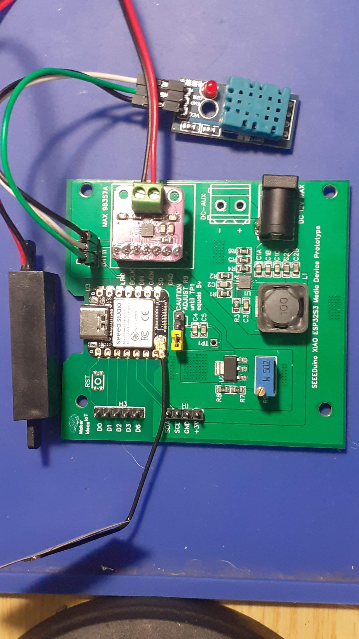
So what is on the PCB?

As mentioned above, I had a few goals with this prototype. Let us take a quick look at the board and its components.
Starting bottom left, we have the DC input area. Here I chose to provide both a DC Barrel Jack, as well as a screw Terminal. Both can be used, but I believe the screw terminal will add a bit more flexibility in an actual installation inside an enclosure.
To the right of those, we have a 7-way header. This provides access to D7 to D10 on the XIAO, and, in my case, is labelled for use with the I2S module and a DHT11 sensor. ( you can of course use it for something else as well). The DHT11 header is on the far right in this picture.
At the centre-left, the components around U1 forms the DC-DC buck converter. This is set to supply 3.3v at a maximum current of 3A.
To the right of that, around TP1, is a jumper to that supplies the XIAO with 5v from U2 ( the LM317G ). It is important to note that you should leave this jumper disconnected at first power-up, and then adjust R9 while measuring between GND and TP1 to get a voltage of exactly 5v on TP1. This will prevent you from damaging the XIAO module. Once that is set, power down, and place a jumper on the center and right side pins. Make sure to NOT adjust R9 again with this jumper in place.
Center-right is the star of the board. The XIAO ESP32S3 Module ( marked U3)
Note the cutout for the USB-C connector at its top.
A reset button, marked RST, and two headers, one for I2C and another with additional GPIO pins completes the PCB.
Note that the XIAO ESP32S3 makes use of an external antenna on a short UFL connected cable. Make sure to attach this BEFORE you power up the board for the first time.
Manufacturing
Since I have made use of a SEEED Module, I sent this to SEEED Studio for manufacturing.
Seeed Studio’s Fusion service seamlessly marries convenience with full-feature capabilities in one simple platform. Whether you are prototyping or looking for a mass production partner or based on open source product customization requirements and other design manufacturing services, Seeed Studio Fusion service is catered to your needs starting with a simple online platform. https://www.seeedstudio.com/fusion.html
Assembly and Testing
I chose to assemble this project on my own. There was some issue with component availability, and since I have most in stock myself, decided to save time and do it myself.

Little did I know that I will be severely handicapped by a broken wrist a few weeks later. That little incident forced me to use my non-dominant hand, and resulted in an almost 3-hour-long assembly operation! All did however go well, and everything works as expected.
Testing went well, and after verifying all the voltages and connections, I uploaded some previously prepared ESPHome code to the board.
Due to the fact that this is still an early prototype, as well as some issues with ESPHome, I wont be releasing the firmware just yet. That will however happen in the near future.


