
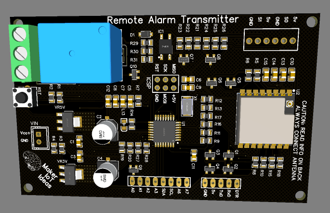
As part of my experiments with LoRa and the easy to use ATMega328P, I have recently designed quite a few LoRa based projects. In this final 2 part series, I will look at two additional projects, part of a Remote Alarm Transceiver, where I experimented with a changing a few things:
– Using LM317G adjustable voltage regulators.
– Replacing my standard N-MOS based logic level converters with a dedicated chip.

How does this differ from my other LoRa Based projects?
The PCB presented above does in fact not really differ a lot from any of my existing LoRa based projects.
However, there are a few subtle changes, mainly experimental changes, brought on by factors such as component availability and an attempt to reduce component counts and board size.
The first of these changes is using the LM317G voltage regulator, in the place of my usual LM1117 3.3 and 5.0 LDO regulators.
The LM317 is an old device, It has been on the market for a long time. It can supply up to 1.5A of current, and a single device can be configured to supply a wide range of different voltages by just changing two resistors. This seemed quite attractive to me, as it is getting quite difficult to reliably get quite a few components on time, and with decent pricing in the post-Covid-19 world.
The second major change would be moving away from my existing N-Mos based Logic converter setup, where I used the BSS138 and 10K resistors as logic converters. This setup works perfectly, but it has the drawback of requiring quite a lot of components. for example:
To provide logic conversion to an RA-02 module, with access to all the IO Lines (GPIO0-5 included) required 12 BSS138 Mosfets and 24 10k resistors. This is quite a lot of components. A dedicated logic converter chip would thus be a much more attractive solution.
Driver circuitry for sensor Inputs, consisting of a simple transistor input, and an optically isolated Relay output completes the circuit.
Using the LM317

The output voltage of the LM317 is typically set using two resistors, with a suitable current rating, using the following Formula
VOUT = 1.25 * ( 1 + R2/R1 )
It is also common to use a variable resistor at R2, to have fine control over the output voltage. This is due to the fact that stock resistor values do not always give you the exact voltage you require. You should also take into account that using a 5% resistor will be less accurate than a 1% resistor.
The grid below is a list of common stock resistor values for R1/R2, with the resulting voltage produced.
R1 vs R2 Grid for use in selecting fixed output voltage
| R2\R1 | 150 | 180 | 220 | 240 | 270 | 330 | 370 | 390 | 470 |
| 68 | 1.82 | 1.72 | 1.64 | 1.60 | 1.56 | 1.51 | 1.48 | 1.47 | 1.43 |
| 82 | 1.93 | 1.82 | 1.72 | 1.68 | 1.63 | 1.56 | 1.53 | 1.51 | 1.47 |
| 100 | 2.08 | 1.94 | 1.82 | 1.77 | 1.71 | 1.63 | 1.59 | 1.57 | 1.52 |
| 120 | 2.25 | 2.08 | 1.93 | 1.88 | 1.81 | 1.70 | 1.66 | 1.63 | 1.57 |
| 150 | 2.50 | 2.29 | 2.10 | 2.03 | 1.94 | 1.82 | 1.76 | 1.73 | 1.65 |
| 180 | 2.75 | 2.50 | 2.27 | 2.19 | 2.08 | 1.93 | 1.86 | 1.83 | 1.73 |
| 220 | 3.08 | 2.78 | 2.50 | 2.40 | 2.27 | 2.08 | 1.99 | 1.96 | 1.84 |
| 240 | 3.25 | 2.92 | 2.61 | 2.50 | 2.36 | 2.16 | 2.06 | 2.02 | 1.89 |
| 270 | 3.50 | 3.13 | 2.78 | 2.66 | 2.50 | 2.27 | 2.16 | 2.12 | 1.97 |
| 330 | 4.00 | 3.54 | 3.13 | 2.97 | 2.78 | 2.50 | 2.36 | 2.31 | 2.13 |
| 370 | 4.33 | 3.82 | 3.35 | 3.18 | 2.96 | 2.65 | 2.50 | 2.44 | 2.23 |
| 390 | 4.50 | 3.96 | 3.47 | 3.28 | 3.06 | 2.73 | 2.57 | 2.50 | 2.29 |
| 470 | 5.17 | 4.51 | 3.92 | 3.70 | 3.43 | 3.03 | 2.84 | 2.76 | 2.50 |
| 560 | 5.92 | 5.14 | 4.43 | 4.17 | 3.84 | 3.37 | 3.14 | 3.04 | 2.74 |
| 680 | 6.92 | 5.97 | 5.11 | 4.79 | 4.40 | 3.83 | 3.55 | 3.43 | 3.06 |
| 820 | 8.08 | 6.94 | 5.91 | 5.52 | 5.05 | 4.36 | 4.02 | 3.88 | 3.43 |
| 1000 | 9.58 | 8.19 | 6.93 | 6.46 | 5.88 | 5.04 | 4.63 | 4.46 | 3.91 |
| 1200 | 11.25 | 9.58 | 8.07 | 7.50 | 6.81 | 5.80 | 5.30 | 5.10 | 4.44 |
| 1500 | 13.75 | 11.67 | 9.77 | 9.06 | 8.19 | 6.93 | 6.32 | 6.06 | 5.24 |
| 1800 | 16.25 | 13.75 | 11.48 | 10.63 | 9.58 | 8.07 | 7.33 | 7.02 | 6.04 |
| 2200 | 19.58 | 16.53 | 13.75 | 12.71 | 11.44 | 9.58 | 8.68 | 8.30 | 7.10 |
| 2700 | 23.75 | 20.00 | 16.59 | 15.31 | 13.75 | 11.48 | 10.37 | 9.90 | 8.43 |
| 3300 | 28.75 | 24.17 | 20.00 | 18.44 | 16.53 | 13.75 | 12.40 | 11.83 | 10.03 |
As you can see from the table above, using stock resistors, the output voltage is reasonably accurate, but it is quite obvious that you will need a potentiometer to get exact values.
Another issue will definitely be heat dissipation. In my PCB design, I have used the SOT-223 package of the component, with a PCB heatsink, built directly into the layers. With the LM1117 LDO regulators, these work extremely well.
Logic Level Conversion
In this design, I used my standard Logic Level conversion circuit, comprised of a BSS138 N-Mos with two 10 k resistors. This circuit, although a bit cumbersome with lots of components if you need many logic converters, is very stable, and functions extremely well.
Conclusion
This circuit was designed as a two-part prototype, with the goal of experimenting with different voltage regulators, and in part 2, with a single chip 8 channel logic converter. As such, I do not feel comfortable releasing the full schematics to you at this stage, do so anyway in the interest of learning. The circuit works, but there are many issues with the regulators:


– Overheating at input voltages above 8.0v
The PCB heatsink will have to be improved, or even a different package for the LM317 with the possibility to attach an external heatsink.
– The voltages do not seem stable, especially on the 3.3-volt side.
Manufacturing the PCB

This PCB was manufactured at PCBWAY. The Gerber files and BOM, as well as all the schematics, will soon be available as a shared project on their website. If you would like to have PCBWAY manufacture one of your own, designs, or even this particular PCB, you need to do the following…
1) Click on this link
2) Create an account if you have not already got one of your own.
If you use the link above, you will also instantly receive a $5USD coupon, which you can use on your first or any other order later. (Disclaimer: I will earn a small referral fee from PCBWay. This referral fee will not affect the cost of your order, nor will you pay any part thereof.)
3) Once you have gone to their website, and created an account, or login with your existing account,

4) Click on PCB Instant Quote

5) If you do not have any very special requirements for your PCB, click on Quick-order PCB

6) Click on Add Gerber File, and select your Gerber file(s) from your computer. Most of your PCB details will now be automatically selected, leaving you to only select the solder mask and silk-screen colour, as well as to remove the order number or not. You can of course fine-tune everything exactly as you want as well.


7) You can also select whether you want an SMD stencil, or have the board assembled after manufacturing. Please note that the assembly service, as well as the cost of your components, ARE NOT included in the initial quoted price. ( The quote will update depending on what options you select ).

8) When you are happy with the options that you have selected, you can click on the Save to Cart Button. From here on, you can go to the top of the screen, click on Cart, make any payment(s) or use any coupons that you have in your account.
Then just sit back and wait for your new PCB to be delivered to your door via the shipping company that you have selected during checkout.