Sound or music adds another level of complexity to any project. Having the ability to easily add it as a shield, allows for a reduced level of this complexity, and hopefully stimulates some inspiration along the way.
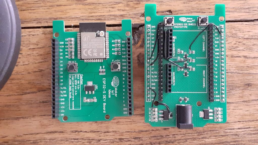
This was the thought process that inspired this Stereo I2S Shield, for use with my ESP32-S Dev Board. During the design process, and actually, before, many things happened that turned this project into a slightly more complicated task than I have initially accounted for.
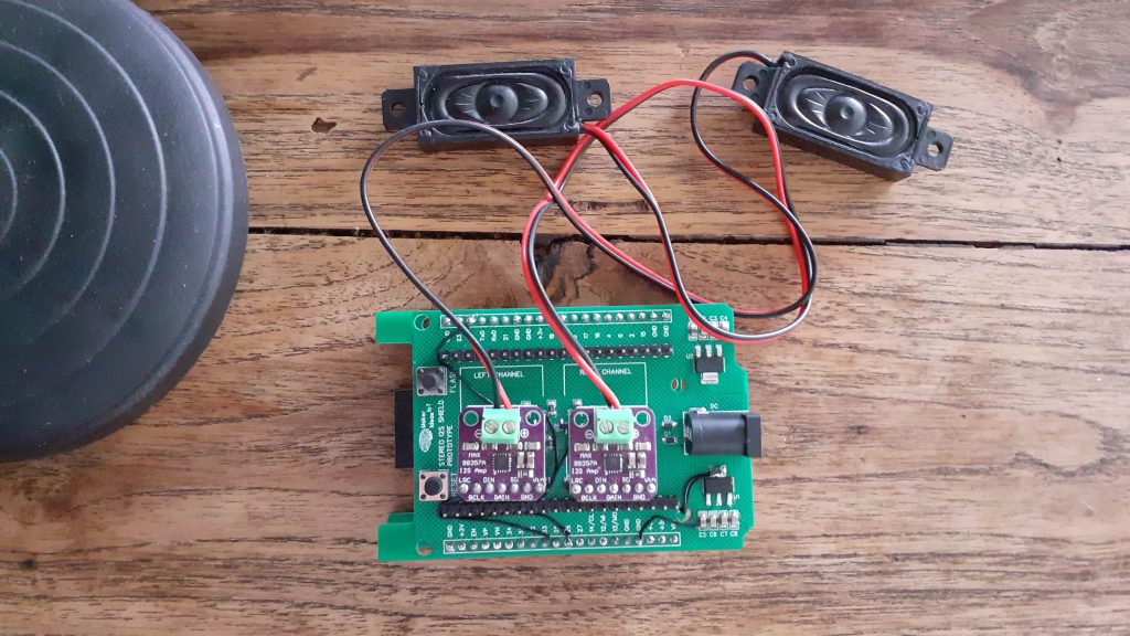
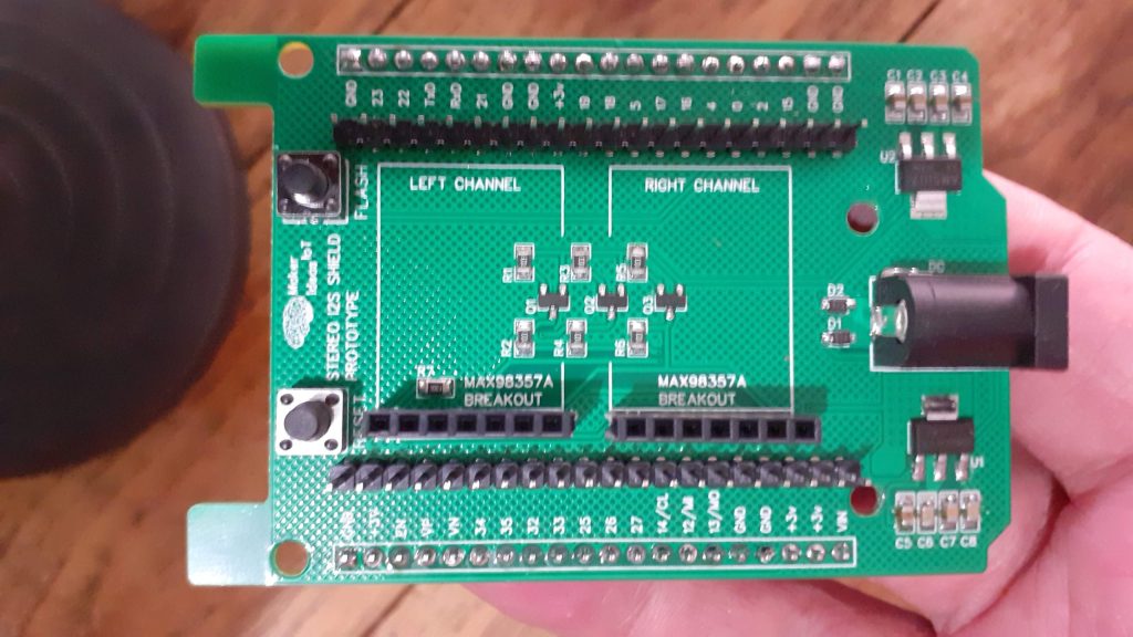
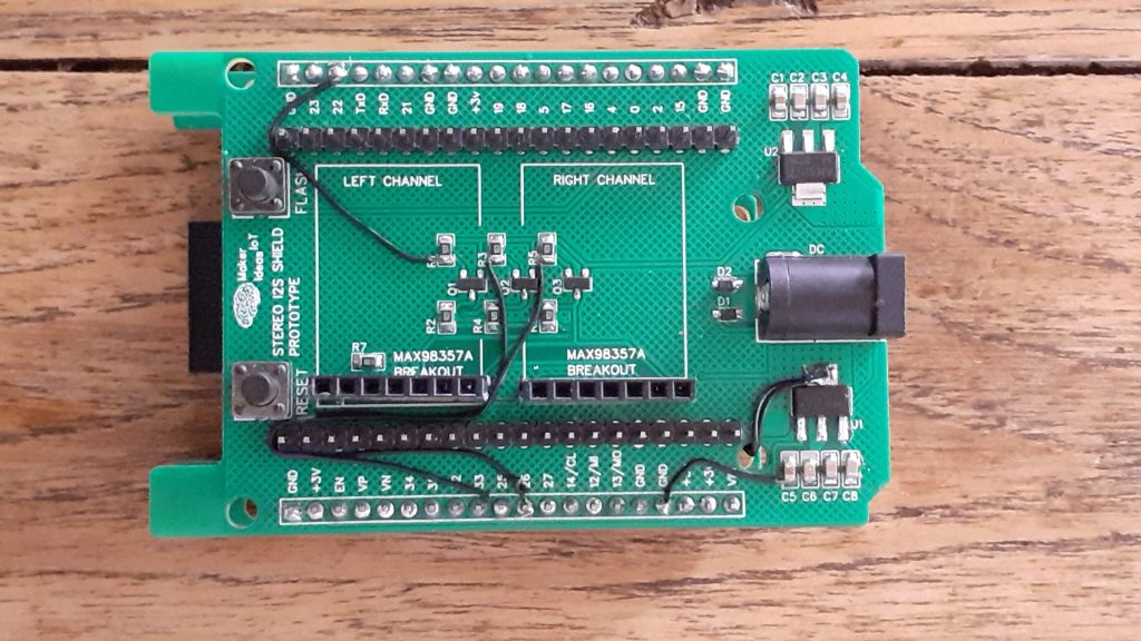
The short and sweet is that I made a few silly mistakes on the PCB, which, for the prototype at least, has been fixed with a few jumper wires. [ I have since updated the Gerber files with the correct design, omitting these silly mistakes.]
Let us take a look at what happened.
- I forgot the ground connection on the 5v Regulator, and since I placed extensive ground copper pours on both sides of the PCB, I missed that one completely.
- I forgot to connect the 5v supply to the Max98357A breakout headers
- I also completely forgot to connect any signal traces to these breakouts
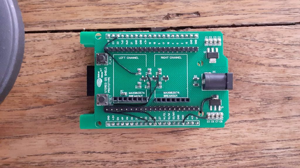
- The breakouts were placed on the wrong side of the PCB ( if looking top to bottom on the picture below, they should be towards the top)
How does this happen, and most importantly, why would I even mention my mistakes here, in public?
The most important here is that I am human. Humans make mistakes. Rushing through converting a design that works perfectly on a breadboard onto a PCB should not happen, but it does happen, and that is why the first iterations of a PCB are called prototypes. Dealing with customers, while working on a design, as well as life’s other interruptions very often results in small mistakes, which I usually catch before a board goes for manufacturing. In this case, I did not catch them until after I received the board back from the factory.
The other part of this coin is transparency. There are many many projects on the internet, some good, some excellent, and some outright terrible. Without giving a score to any of my own, my only intention is that whatever I present on this medium MUST be completely honest, my own work, and it must work. Any mistakes MUST be made public, regardless of what the public thinks of it afterwards.
With the ranting done now, let’s take a look at the board, which, after fixing the issues, actually works perfectly…
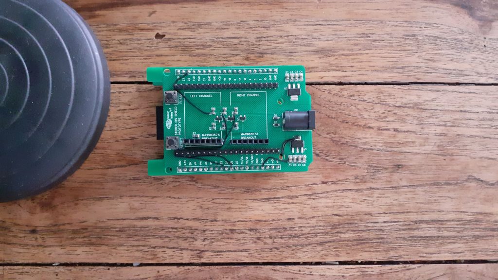
(I will make use of a rendered image showing the repaired PCB, as it will be the least confusing)
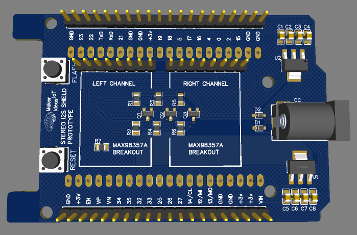
In the rendered image above, we can clearly see what it should have looked like, with the MAX98357A breakouts in their correct places, and all power and signal traces connected correctly.
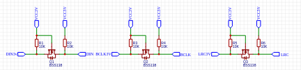
Part of the reason for the mistakes on the initial prototype PCB was that I felt it necessary to add logic-level conversion to the I2S modules. The reason for that is that in order to get a bit more volume out of them, they are powered at 5v.
With the GPIO pins of the ESP32 being 3.3v, I felt that it is not warranted to take a risk and power the I2S breakouts at 5v, and send them 3.3v signals. That sparked the whole issue, with adding my standard Bss138-based logic converter circuit to the mixture.
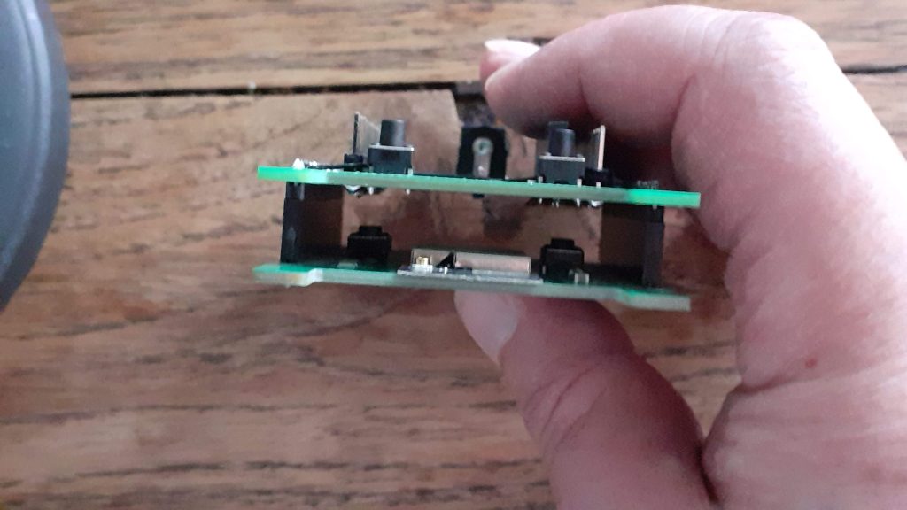
The board contains its own Flash and Reset buttons, which are slaved to the stacked ESP32-S dev board at the bottom.
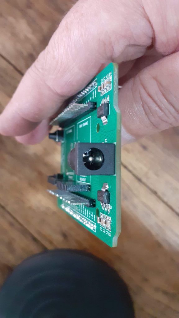
Further to that, the board provides a DC barrel connector, which will power the I2S shield, as well as the ESP32-S dev board via its Vin Pin
Since the MAX98357A breakouts seem to pull quite a bit of current ( about 500mA or more each, depending on the volume), the shield has its own voltage regulators. I have found that during the experimentation on the breadboard, the single 3.3v regulator on the ESP32-S Dev board was a bit inadequate to drive two of these modules and the ESP32 as well.
Software and Code
The code for the device is far from perfect at this stage, consisting mainly of example code that was provided by the i2s library, to which I have started making minor changes, the most significant being moving the entire audio process to an alternate core of the ESP32. This was done because the audio process seem to be blocking, and, as I plan to later add controls and displays to this device, that would result in an issue later.
/*
  Simple Internet Radio Demo
  esp32-i2s-simple-radio.ino
  Simple ESP32 I2S radio
  Uses MAX98357 I2S Amplifier Module
  Uses ESP32-audioI2S Library - https://github.com/schreibfaul1/ESP32-audioI2S


*/

// Include required libraries

#include "Arduino.h"
#include "WiFi.h"
#include "Audio.h"
#include "ESPmDNS.h"
#include "time.h"


// Define I2S connections
#define I2S_DOUT  22
#define I2S_BCLK  26
#define I2S_LRC   25


// Create audio object
Audio audio;

// Wifi Credentials
String ssid =    "<your ssid here>";
String password = "<your password here>";

void audioTask(void *pvParameters) {
  while(1) {
    audio.loop();
  }
}


void setup() {

  // Start Serial Monitor
  Serial.begin(115200);


  // Setup WiFi in Station mode
  WiFi.disconnect();
  WiFi.mode(WIFI_STA);
  WiFi.begin(ssid.c_str(), password.c_str());

  while (WiFi.status() != WL_CONNECTED) {
    delay(500);
    Serial.print(".");
  }

  // WiFi Connected, print IP to serial monitor
  Serial.println("");
  Serial.println("WiFi connected");
  Serial.println("IP address: ");
  Serial.println(WiFi.localIP());
  Serial.println("");

  // Connect MAX98357 I2S Amplifier Module
  audio.setPinout(I2S_BCLK, I2S_LRC, I2S_DOUT);

  // Set thevolume (0-100)
  audio.setVolume(10);

  // Connect to an Internet radio station (select one as desired)
  //audio.connecttohost("http://vis.media-ice.musicradio.com/CapitalMP3");
  //audio.connecttohost("mediaserv30.live-nect MAX98357 I2S Amplifier Module
  //audio.connecttohost("www.surfmusic.de/m3u/100-5-das-hitradio,4529.m3u");
  //audio.connecttohost("stream.1a-webradio.de/deutsch/mp3-128/vtuner-1a");
  //audio.connecttohost("www.antenne.de/webradio/antenne.m3u");
  //audio.connecttohost("0n-80s.radionetz.de:8000/0n-70s.mp3");
  //audio.connecttohost("http://live.webhosting4u.gr:1150/stream");
  audio.connecttohost("0n-80s.radionetz.de:8000/");
  disableCore0WDT();
  xTaskCreatePinnedToCore(audioTask,"audiotask",10000,NULL,15,NULL,0);
}


void loop()

{
  // Run audio player
  //audio.loop();

}


//

// Audio status functions

void audio_info(const char *info) {
  Serial.print("info        "); Serial.println(info);
}
void audio_id3data(const char *info) { //id3 metadata
  Serial.print("id3data     "); Serial.println(info);
}
void audio_eof_mp3(const char *info) { //end of file
  Serial.print("eof_mp3     "); Serial.println(info);
}
void audio_showstation(const char *info) {
  Serial.print("station     "); Serial.println(info);
}
void audio_showstreaminfo(const char *info) {
  Serial.print("streaminfo  "); Serial.println(info);
}
void audio_showstreamtitle(const char *info) {
  Serial.print("streamtitle "); Serial.println(info);
}
void audio_bitrate(const char *info) {
  Serial.print("bitrate     "); Serial.println(info);
}
void audio_commercial(const char *info) { //duration in sec
  Serial.print("commercial  "); Serial.println(info);
}
void audio_icyurl(const char *info) { //homepage
  Serial.print("icyurl      "); Serial.println(info);
}
void audio_lasthost(const char *info) { //stream URL played
  Serial.print("lasthost    "); Serial.println(info);
}
void audio_eof_speech(const char *info) {
  Serial.print("eof_speech  "); Serial.println(info);
}
Important parts of the code to note are as follows
disableCore0WDT();
  xTaskCreatePinnedToCore(audioTask,"audiotask",10000,NULL,15,NULL,0);
This code disables the Watchdog Timer on Core0 of the ESP32, as well as creates the audio task, which is defined earlier in the code
void audioTask(void *pvParameters) {
  while(1) {
    audio.loop();
  }
}
It is also important to note that the loop() in the code is essentially empty, with all code commented out. As mentioned above, I do plan to add additional functionality later, and in that case, there will either be other tasks running, or be some code in the main loop.
Another VERY important issue is the DOUT pin, which I have defined as GPIO22.
This pin is usually used as an I2C pin, but it seems that the I2S hardware on the ESP32-S does not like running the DOUT signal on another pin. This is not an issue, as you can assign another pin to I2C without any issue if you need to use that as well.
Manufacturing
I choose PCBWay for my PCB manufacturing. Why? What makes them different from the rest?
PCBWay‘s business goal is to be the most professional PCB manufacturer for prototyping and low-volume production work in the world. With more than a decade in the business, they are committed to meeting the needs of their customers from different industries in terms of quality, delivery, cost-effectiveness and any other demanding requests. As one of the most experienced PCB manufacturers and SMT Assemblers in China, they pride themselves to be our (the Makers) best business partners, as well as good friends in every aspect of our PCB manufacturing needs. They strive to make our R&D work easy and hassle-free.
How do they do that?
PCBWay is NOT a broker. That means that they do all manufacturing and assembly themselves, cutting out all the middlemen, and saving us money.
PCBWay’s online quoting system gives a very detailed and accurate picture of all costs upfront, including components and assembly costs. This saves a lot of time and hassle.
PCBWay gives you one-on-one customer support, that answers you in 5 minutes ( from the Website chat ), or by email within a few hours ( from your personal account manager). Issues are really resolved very quickly, not that there are many anyway, but, as we are all human, it is nice to know that when a gremlin rears its head, you have someone to talk to that will do his/her best to resolve your issue as soon as possible.
Find out more here

Assembly
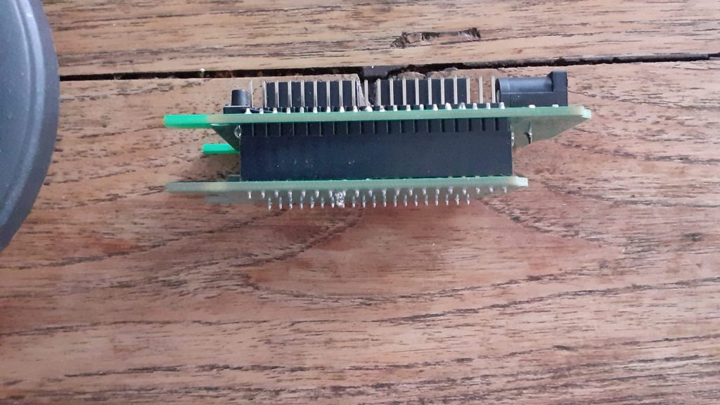
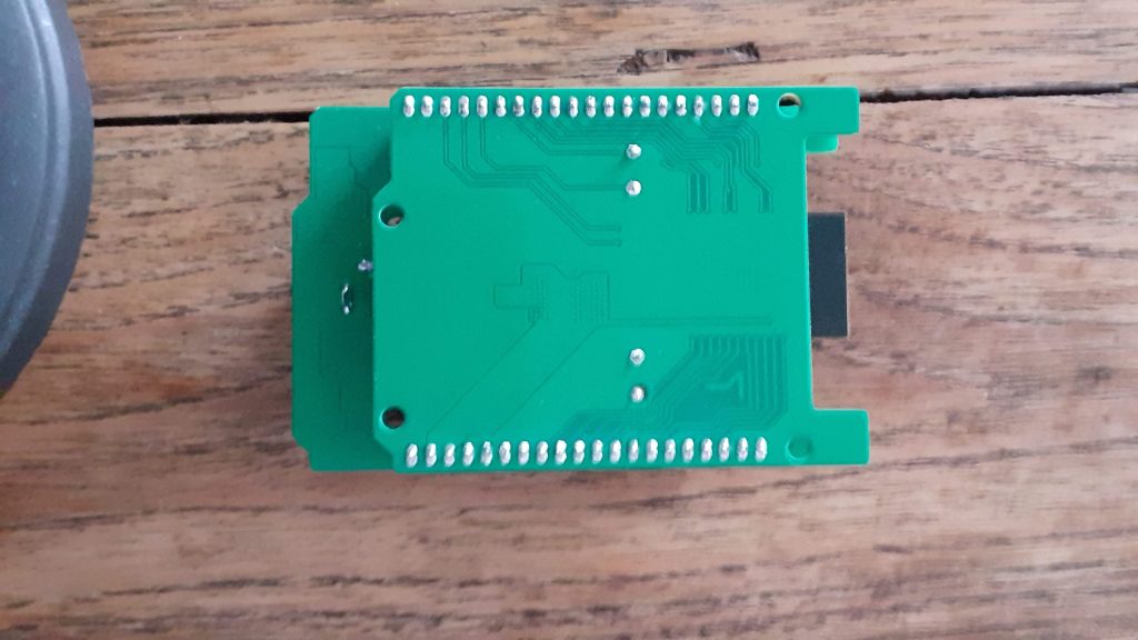
Assembly was straightforward, with no issues, as all of the components can quite easily be soldered using a standard soldering iron, or hot air. This PCB does not require a stencil, but, you can of course have one made if you want to.
As mentioned in the introduction, I had to do a lot of after-assembly-hacking to get the board to work correctly. This will however not be needed with the second-generation PCB, as I have already fixed all those issues on the Gerber files.
Picture Gallery