
In the first part of this series, I showed you how to extend the available output pins on your microprocessor by using a SIPO (Serial In, Parallel Out) Shift Register. These work great to extend your outputs, but they do tend to involve a bit of extra work and organisation in your code. They are also a bit slower than the normal GPIO pins, because data has to be serially shifted into them, and then latched out onto the parallel port.
I have also mentioned that there are I2C devices available that can make this much easier… In today’s article, I will show you how to use one of these I2C devices, the PCF8574.
These little modules have some quite impressive features, for one, allowing you to cascade up to 8 of them together, giving you a quite impressive 64 GPIO ports ! I am also happy to tell you, that if you can find the PCF8574A variant, as well, you can increase the total amount of ports to 128! ( If you chain 8x PCF8574 as well as 8x PCF8574A together) This is possible because the I2C addresses of the two series of chips are different. Thus allowing us to add a total of 16 of them to the I2C bus.
It must however be said that you should calculate your bus resistance very carefully if you plan on doing that. For most of us, I do not believe we will need that much GPIO on a single microprocessor!
Enough introduction, let us start by looking closely at the chip, as well as the modules that you can purchase for around 1 USD each…
A word of caution, there is also another version of these available, which is specifically designed to be used with LCD screens. You should thus be careful when you buy a premade module, that you choose the io-extender version, and not the LCD controller version.
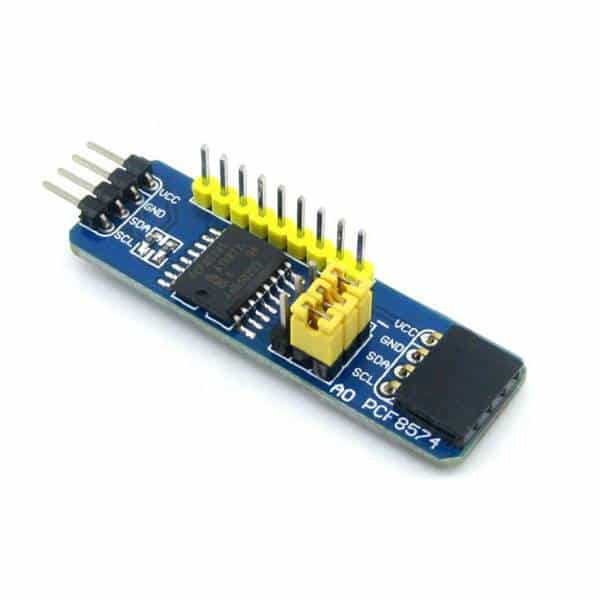
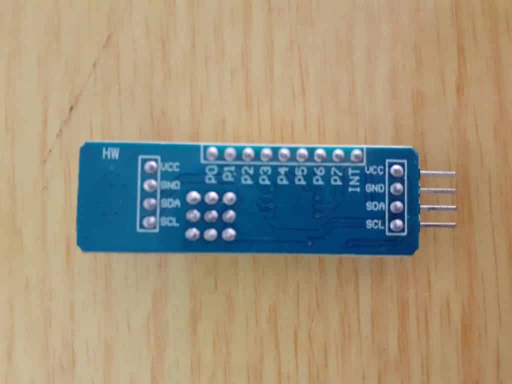
As we can see, the GPIO ports are clearly labeled, from P0 to P7, with the INT (Interrupt Pin) on the very right.
As I have said before, you can cascade up to 8 of these onto the I2C bus. This is done by setting the I2C address of the module. This is done by setting the jumpers as seen in the picture below.
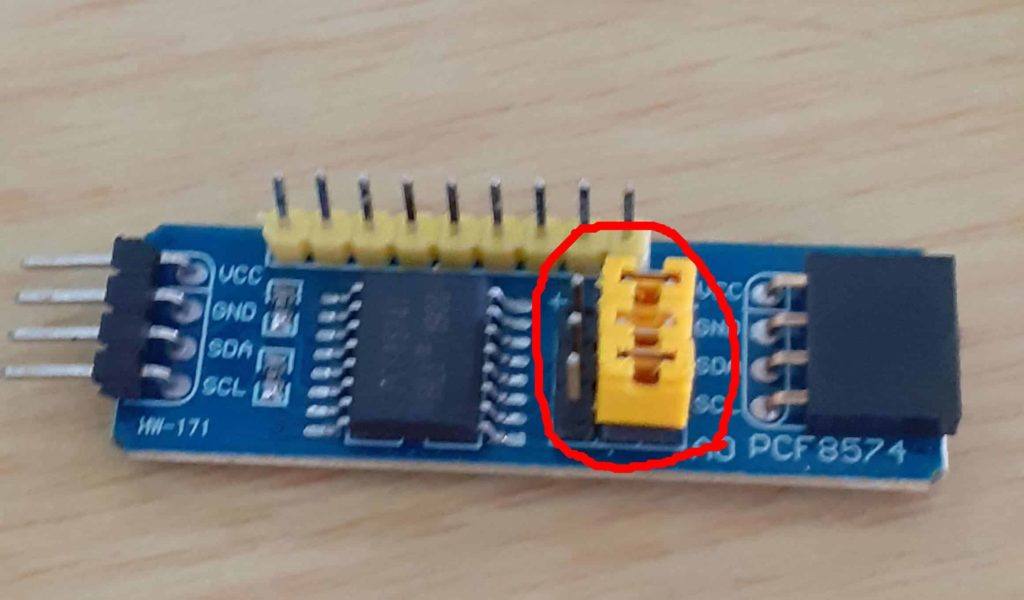
The Address can be set by using the following table to lookup the address and set the jumpers accordingly.
| A2 | A1 | A0 | I2C Device Address |
| 0 | 0 | 0 | 0x20 |
| 0 | 0 | 1 | 0x21 |
| 0 | 1 | 0 | 0x22 |
| 0 | 1 | 1 | 0x23 |
| 1 | 0 | 0 | 0x24 |
| 1 | 0 | 1 | 0x25 |
| 1 | 1 | 0 | 0x26 |
| 1 | 1 | 1 | 0x27 |
Connecting the device is very easy. You only have to supply 5v and Ground, as well as connect it to the SCL and SDA Pins on your microprocessor. For Arduino Uno / Nano that is A4 (SDA) and A5 (SCL)
As far as the coding is concerned, you have two options. You can either use the built-in Wire library, or you can download a special library. Both works equally well, but I do believe that the built-in Wire library might be a little bit faster.
Another point to make is that there are a lot of “fake” modules on the market these days. These modules work, but some of them have extremely weak current sourcing abilities. ( I recently bought a pair online, and they are unable to properly light an LED even without a current limiting resistor. I fixed that issue by driving the LED through a small BJT transistor, like the 2n2222a.
You should also take note that the ports will start up in a weak HIGH state when the module is powered up. This should be taken into consideration when designing your circuit to drive external devices through the outputs. In other words, you should take precautions to prevent the devices from switching on before the microprocessor takes control of the module.
Let us start to look at the coding that you will need to do to use this device.
I will start with the built-in wire Library that is included with the Arduino IDE.
#include <Wire.h> // Wire.h provide access to I2C functions
void setup()
{
Wire.begin(); // Start I2C
}
void loop()
{
Wire.beginTransmission(0x20); // Our device is on Address 0x20
Wire.write(0x0F); // This is equal to 0b00001111, meaning it will switch ports P0 to P3 High
Wire.endTransmission();
delay(1000);
Wire.beginTransmission(0x20);
Wire.write(0xF0); // This is equal to 0b11110000, meaning it will switch ports P4 to P7 High
Wire.endTransmission();
delay(1000);
}
The code above will alternate between switching 4 ports high and low every one second.
You can observe this by connecting 8 LEDs through 330ohm resistors to ports P0 through P7
Reading the status of a port (meaning that you configured it as an input) can be done using the following code
#include<Wire.h>
void setup()
{
Serial.begin(9600);
Wire.begin();
Wire.beginTransmission(0x20);
Wire.write(0x00); //LED1 is OFF
Wire.endTransmission();
}
void loop()
{
Wire.requestFrom(0x20, 4); // Read the state of P4
byte x = Wire.read();
if (bitRead(x, 4) == LOW)
{
Wire.beginTransmission(0x20);
Wire.write(0x01); //LED1 is ON
Wire.endTransmission();
}
else
{
Wire.beginTransmission(0x20);
Wire.write(0x00); //LED1 is OFF
Wire.endTransmission();
}
delay(1000);
}
This code assumes that you have connected a LED throught a resistor to P0, and that you have connected a pullup resistor of 10k to P4, with a pushbutton to GROUND.
The LED should switch on when you press the switch, and go off again once you release it.
If you want to use the special library, you can download it below:
Install this into your Arduino Libraries, and use the following code:
include “Arduino.h”
include “PCF8574.h
// Set i2c address
PCF8574 pcf8574(0x20);
void setup()
{
Serial.begin(115200);
// Set pinMode to OUTPUT
pcf8574.pinMode(P0, OUTPUT);
pcf8574.begin();
}
void loop()
{
pcf8574.digitalWrite(P0, HIGH);
delay(1000);
pcf8574.digitalWrite(P0, LOW);
delay(1000);
}
Reading the status of an Input can be done like this:
include “Arduino.h”
include “PCF8574.h”
// Set i2c address
PCF8574 pcf8574(0x20);
void setup()
{
Serial.begin(115200);
pcf8574.pinMode(P0, OUTPUT);
pcf8574.pinMode(P1, INPUT);
pcf8574.begin();
}
void loop()
{
uint8_t val = pcf8574.digitalRead(P1);
if (val==HIGH) Serial.println(“KEY PRESSED”);
delay(50);
}
There are also excellent examples included with the library. These include using the interrupt pin.
I hope that this will be useful to somebody.