
Introduction
Schematic
How does it work? / How do I use it?
– Arduino Example
– ESP32 Example
Where can I get my own version?
Introduction
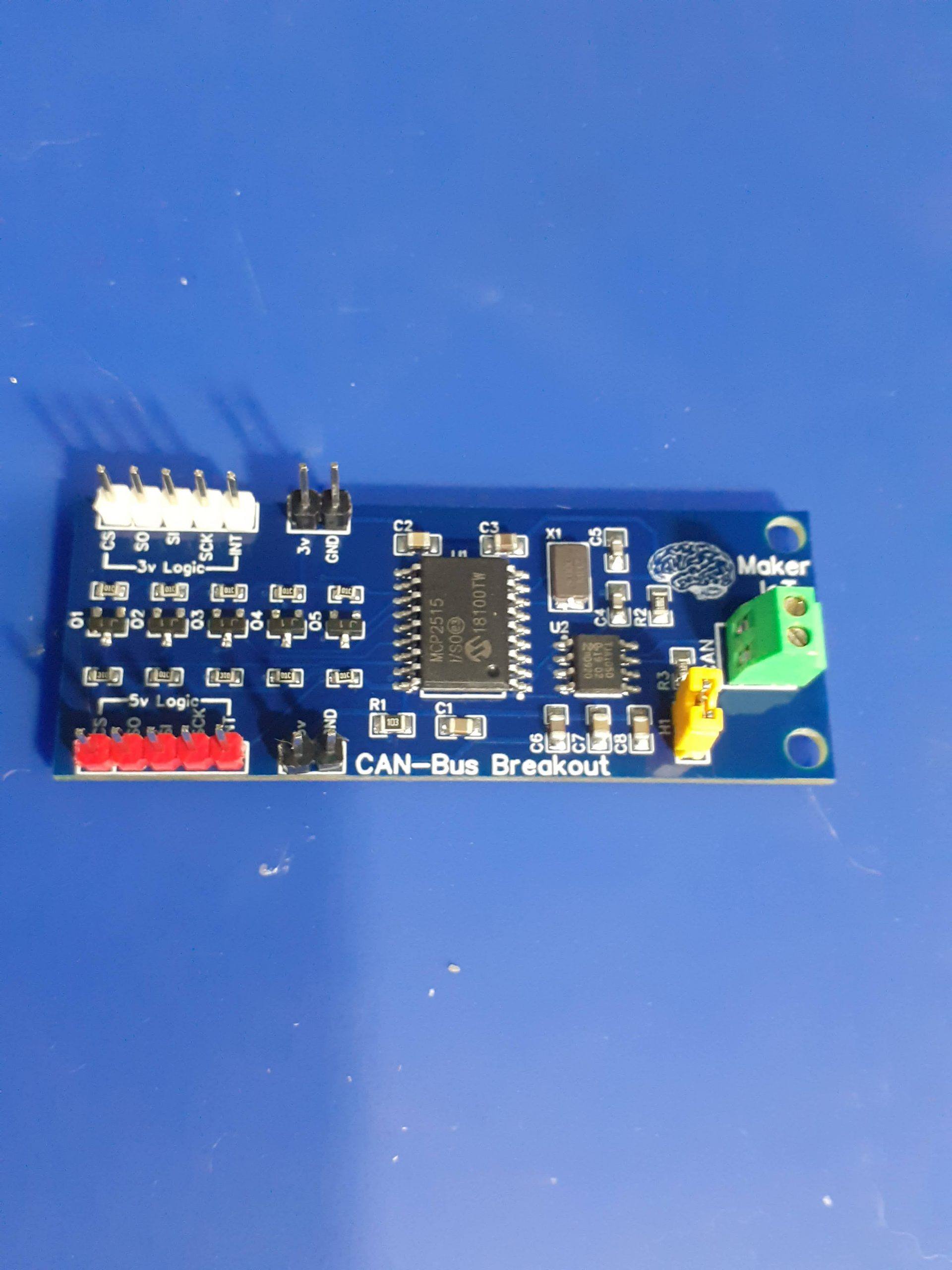
There are many CAN-Bus modules available for purchase to the DIY Electronics Enthusiast and the Maker community. Our Level Converted CAN-BUS module is different. Where the standard modules are all 5v devices, ours are level converted, allowing you to interface it with 3v and 5v microcontrollers, the choice is yours…


The Schematic

How does it work? / How do I use it?
The Level Converted CAN-BUS Module is based on the MCP2515 CAN Controller from Microchip, with the TJA1050 CAN Tranceiver used for communicating with the CAN-Bus. These two chips are extremely cheap and easy to get hold of, but they are also one of the main reasons for the redesign of the module.
While the MCP2515 is useable with a voltage range of 2.5v to 5v, the TJA1050 is not. When using the commercially available CAN-Bus modules, this limits you to using 5v microcontrollers, or for the more informed, using level converters in-between to translate back and forth to the desired logic levels.
The MCP2515 is an SPI device, and in my opinion, having long wires on an SPI bus is not always the best way of doing things, due to ringing and other undesirable interference. Having to add a level converter module into this already questionable setup, can add a lot of other undesirable effects.
I have thus decided to design and manufacture my own module, with 5 level converters directly on the PCB, thus reducing the length of connecting wires, as well as reducing complexity.
Using the device is now as easy as providing a 5v voltage source, as well as an additional 3v source if you need the level converters, and connecting your microcontroller to the appropriately marked logic side of the module.
A jumper at H1 can be set/unset to enable the 120ohm ballast resistor that is needed on the CAN-Bus for very short distance connections.
Example connection to an Arduino
Use the 5v logic side, and power the module with 5v and ground. You do not need a 3v power source.
Connect the pins as follows:
CS pin to Arduino Pin 10
SO to the MISO pin on the Arduino Pin 12
SI to the MOSI pin on the Arduino, Pin 11
SCK to the SCK pin on the Arduino, Pin 13
INT to an interrupt capable pin on the Arduino, usually pin 2 or 3
Example connection to an ESP32 module
Provide a 5v as well as 3v power source with a common ground connection.
Connect your logic to the 3v logic side of the PCB Module.
CS pin to GPIO2
SO to the MISO pin, GPIO19
SI to the MOSI pin, GPIO23
SCK to the SCK pin, GPIO18
INT to an interrupt capable pin on the ESP32
Where can I get my own version of this module?
This module will be exclusively available from PCBWay for the foreseeable future. Click on this link to order your own, and help support a great company that produces very high-quality PCBs for a very affordable price.

This PCB was manufactured at PCBWAY. The Gerber files and BOM, as well as all the schematics, will soon be available as a shared project on their website. If you would like to have PCBWAY manufacture one of your own, designs, or even this particular PCB, you need to do the following…
1) Click on this link
2) Create an account if you have not already got one of your own.
If you use the link above, you will also instantly receive a $5USD coupon, which you can use on your first or any other order later. (Disclaimer: I will earn a small referral fee from PCBWay. This referral fee will not affect the cost of your order, nor will you pay any part thereof.)
3) Once you have gone to their website, and created an account, or login with your existing account,

4) Click on PCB Instant Quote

5) If you do not have any very special requirements for your PCB, click on Quick-order PCB

6) Click on Add Gerber File, and select your Gerber file(s) from your computer. Most of your PCB details will now be automatically selected, leaving you to only select the solder mask and silk-screen colour, as well as to remove the order number or not. You can of course fine-tune everything exactly as you want as well.


7) You can also select whether you want an SMD stencil, or have the board assembled after manufacturing. Please note that the assembly service, as well as the cost of your components, ARE NOT included in the initial quoted price. ( The quote will update depending on what options you select ).

8) When you are happy with the options that you have selected, you can click on the Save to Cart Button. From here on, you can go to the top of the screen, click on Cart, make any payment(s) or use any coupons that you have in your account.
Then just sit back and wait for your new PCB to be delivered to your door via the shipping company that you have selected during checkout.