A breadboard friendly MCP23017

I2C port extenders or expanders are extremely useful devices, and I use quite a lot of them in my projects. My go-to device is definitely the PCF8574, mainly because it is sort of “breadboard friendly”. The MCP23017, with the existing breakouts available locally, are not. I have thus decided to design my own version of a breadboard friendly MCP23017 breakout board.

The Breakout Module PCB and its features

A breadboard friendly MCP23017 breakout board – Front
a breadboard friendly MCP23017 breakout board – Back

While this was definitely one of my easier projects, It still took a bit of time to get it just right and add some essential components and features directly onto the PCB.

The main features of this breakout:
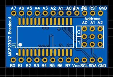
– DIP12 Layout – with all pins broken out, address pins to jumper headers…
– Proper decoupling capacitors, as close as possible to the MCP23017 chip.
I had to make use of the back layer of the PCB to do this, not exactly ideal, but with proper power and ground planes, and nice thick tracks, I believe they will be just fine.

– Address selector jumpers – The breakouts that are available locally, do not have these.
– Breadboard friendly layout – 33.020mm x 20.320mm [board size], with 15.240mm vertical spacing between the rows of pins, ensures that you can easily fit it onto your breadboard, while still having space to add jumper wires to the pins. Horizontal pin spacing is standard 2.45mm.
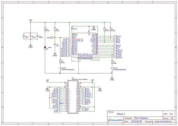
The Schematic

The schematic is plain and simple. A few points to note though:
– The address selection header, as well as the io pin headers are not shown on the schematic.
– I2C pullup resistors are set at 1k but can be replaced with more suitable values as required in your circuit

Using the breakout

I have previously written two very detailed articles on using this chip. They are linked below:
Using the MCP23017 with the standard Wire.h library
Using the MCP23017 with the Adafruit MCP23017 library

Manufacturing the PCB

The PCB for this project is currently on its way from China, after having been manufactured at PCBWay.
Please consider supporting them if you would like your own copy of this PCB, or if you have any PCB of your own that you need to be manufactured.

PCBWay

If you would like to have PCBWAY manufacture one of your own, designs, or even this particular PCB, you need to do the following…
1) Click on this link
2) Create an account if you have not already got one of your own.
If you use the link above, you will also instantly receive a $5USD coupon, which you can use on your first or any other order later. (Disclaimer: I will earn a small referral fee from PCBWay. This referral fee will not affect the cost of your order, nor will you pay any part thereof.)
3) Once you have gone to their website, and created an account, or login with your existing account,

4) Click on PCB Instant Quote

5) If you do not have any very special requirements for your PCB, click on Quick-order PCB

6) Click on Add Gerber File, and select your Gerber file(s) from your computer. Most of your PCB details will now be automatically selected, leaving you to only select the solder mask and silk-screen colour, as well as to remove the order number or not. You can of course fine-tune everything exactly as you want as well.

7) You can also select whether you want an SMD stencil, or have the board assembled after manufacturing. Please note that the assembly service, as well as the cost of your components, ARE NOT included in the initial quoted price. ( The quote will update depending on what options you select ).

8) When you are happy with the options that you have selected, you can click on the Save to Cart Button. From here on, you can go to the top of the screen, click on Cart, make any payment(s) or use any coupons that you have in your account.

Then just sit back and wait for your new PCB to be delivered to your door via the shipping company that you have selected during checkout.

Give an old toy car new life…

Give an old toy car new life

Many of us have old toys laying around the house, they belong to our children or the children of our friends. In this article, I will attempt to show you how to give an old toy car new life, as well as hopefully teach a child a few interesting things with electronics.

The inspiration for this article comes from my friend’s 7-year-old boy, who, way too clever for his age, always has a lot of very interesting questions. His mother and I have thus decided to do an experiment:
“Let us try to teach him Arduino programming, so he can start to make his own toys”

Obviously, the challenges in this venture are many…
To name a few:
The boy speaks only Thai, so English is a no-go.
Soldering is out of the question, due to his age, as well as safety issues – All teaching will have to be done on a breadboard.

My challenges apart, this is a project that many people would want to attempt, so it is important to start with a bit of theory.

Controlling a DC Motor from a microcontroller

DC motors, like those found in toy cars, are inductive loads, and that means that they induce electromagnetic fields when switched on or off. These EMF fields can damage your sensitive microcontroller quite easily. Another thing to remember is that your typical microcontroller can only source or sink in the region of 25mA to 50mA of current, not quite enough to drive a motor, let alone a toy car.

Directional control of the motor

In our toy car, we would definitely want the driving motor to be able to change direction, meaning spin forwards or backwards, thereby changing the direction that the car is travelling. This is achieved by using a circuit called an H-Bridge. In this circuit, four transistors, either BJTs or MOSFETs are arranged in a particular way to allow us to change the direction that the motor spins by changing certain logic signals.

Implementing an H-Bridge with switches

In the picture above, we simulate the H-Bridge circuit using slide switches in order to explain the method of operation. It should be clear that the direction is changed by switching on diagonally opposite switches.

Driving a motor with a transistor

In the picture above, we implement a simple, one-directional motor control circuit using a single transistor. This circuit still has the limitation that the motor can only spin in a single direction.

Half of an H-Bridge

In the circuit above, we combine the two motor driver circuits (with PNP and NPN transistor ) to complete one half of the H-Bridge circuit. This circuit still has the limitation that we can only spin the motor in a single direction.

The completed H-Bridge circuit

In the picture above, we added another half H-Bridge to complete the circuit. We will thus have 2 PNP and 2 NPN transistors, which form the completed circuit. This circuit will give us full bi-directional control of the motor. We can also control the speed of the motor if we apply a suitable PWM signal to the bases of the NPN transistors – we do need to be careful of SHOOT THROUGH and shorts though.

My proposed Motor Driving Circuit

the inside of the toy car, without the old broken circuit-board

In the picture above, we can clearly see that there is not a lot going on inside this toy car. An On-Off switch is connected to the battery compartment, and two wires go to the drive- and steering motor.

Interfacing this car to a microcontroller is thus going to require two separate H-Bridge circuits. One for the drive motor, and the second for the steering.

Dual H-Bridge Circuit diagram

I have designed the circuit above to control both motors of the toy car, the control signals are simplified to 2 per H-Bridge, and a common PWM signal to control speed.

Manufacturing the PCB

The PCB for this project is currently on its way from China, after having been manufactured at PCBWay.
Please consider supporting them if you would like your own copy of this PCB, or if you have any PCB of your own that you need to be manufactured.

PCBWay

If you would like to have PCBWAY manufacture one of your own, designs, or even this particular PCB, you need to do the following…
1) Click on this link
2) Create an account if you have not already got one of your own.
If you use the link above, you will also instantly receive a $5USD coupon, which you can use on your first or any other order later. (Disclaimer: I will earn a small referral fee from PCBWay. This referral fee will not affect the cost of your order, nor will you pay any part thereof.)
3) Once you have gone to their website, and created an account, or login with your existing account,

4) Click on PCB Instant Quote

5) If you do not have any very special requirements for your PCB, click on Quick-order PCB

6) Click on Add Gerber File, and select your Gerber file(s) from your computer. Most of your PCB details will now be automatically selected, leaving you to only select the solder mask and silk-screen colour, as well as to remove the order number or not. You can of course fine-tune everything exactly as you want as well.

7) You can also select whether you want an SMD stencil, or have the board assembled after manufacturing. Please note that the assembly service, as well as the cost of your components, ARE NOT included in the initial quoted price. ( The quote will update depending on what options you select ).

8) When you are happy with the options that you have selected, you can click on the Save to Cart Button. From here on, you can go to the top of the screen, click on Cart, make any payment(s) or use any coupons that you have in your account.

Then just sit back and wait for your new PCB to be delivered to your door via the shipping company that you have selected during checkout.


ESP32-S Card Module

ESP32-S Card Module

What is this?

This project is the result of a lot of prototyping, using different MCUs and wanting to find a way to get a standard interface to all the devices.

The idea is to eventually create similar card-type MCU breakout boards, with similar pins in the same position on the 2x20p breakout header,

for example, power, i2c bus, reset and flash will always be in the same position on the female header…

Step 2 from here on would be to design a baseboard, that is capable of providing power, as well as access to the various GPIO pins. I am thinking along the way of a PC motherboard style interface, with “slots” at regular intervals. These “slots” will have access to the SPI, and I2C bus, as well as various other GPIO.

Step 3 would be a series of commonly used input and output “cards” that will plug into the “slots”…

If successful, I plan to design various MCU cards, with various different processors, with the obvious criteria that they are 3v powered.

This could result in a very flexible development platform, where it is possible to reuse the base-board and IO “cards” with any one of the various MCU “cards”.

The Schematic

As seen on the schematic, almost all of the ESP32-S’s pins are broken out, with the exception of those used for internal flash. Reset and Flash circuitry is provided on the PCB, as well as on the 2x20pin female header.

It is worth noting that I did not include any UART to USB circuitry on the card. Flashing should be performed with an external USB-to-UART converter. It will however be included in the base-board.

There is also no power supply circuitry onboard. This was also intentional, as the card is intended to be powered from the base-board. It is however perfectly acceptable to power only the card from a suitable 3.3v DC power supply unit through the 3v and gnd pins on the 2x20pin header.

Where can I get my own version of this module?

This module will be exclusively available from PCBWay for the foreseeable future. Click on this link to order your own, and help support a great company that produces very high-quality PCBs for a very affordable price.

PCBWay

This PCB was manufactured at PCBWAY. The Gerber files and BOM, as well as all the schematics, will soon be available as a shared project on their website. If you would like to have PCBWAY manufacture one of your own, designs, or even this particular PCB, you need to do the following…
1) Click on this link
2) Create an account if you have not already got one of your own.
If you use the link above, you will also instantly receive a $5USD coupon, which you can use on your first or any other order later. (Disclaimer: I will earn a small referral fee from PCBWay. This referral fee will not affect the cost of your order, nor will you pay any part thereof.)
3) Once you have gone to their website, and created an account, or login with your existing account,

4) Click on PCB Instant Quote

5) If you do not have any very special requirements for your PCB, click on Quick-order PCB

6) Click on Add Gerber File, and select your Gerber file(s) from your computer. Most of your PCB details will now be automatically selected, leaving you to only select the solder mask and silk-screen colour, as well as to remove the order number or not. You can of course fine-tune everything exactly as you want as well.

7) You can also select whether you want an SMD stencil, or have the board assembled after manufacturing. Please note that the assembly service, as well as the cost of your components, ARE NOT included in the initial quoted price. ( The quote will update depending on what options you select ).

8) When you are happy with the options that you have selected, you can click on the Save to Cart Button. From here on, you can go to the top of the screen, click on Cart, make any payment(s) or use any coupons that you have in your account.

Then just sit back and wait for your new PCB to be delivered to your door via the shipping company that you have selected during checkout.

Level Converted CAN-BUS Module

Introduction
Schematic
How does it work? / How do I use it?
Arduino Example
ESP32 Example
Where can I get my own version?

Introduction

There are many CAN-Bus modules available for purchase to the DIY Electronics Enthusiast and the Maker community. Our Level Converted CAN-BUS module is different. Where the standard modules are all 5v devices, ours are level converted, allowing you to interface it with 3v and 5v microcontrollers, the choice is yours…

Level Converted CAN-BUS Module
Level converted CAN-Bus Module
Level converted CAN-BUS Module next to a standard commercial module designed for the Arduino ecosystem or similar
Level Converted CAN-BUS Module together with standard CAN-BUS breakout for comparison.

The Schematic

Schematic for the  Level converted CAN-BUS Module

How does it work? / How do I use it?

The Level Converted CAN-BUS Module is based on the MCP2515 CAN Controller from Microchip, with the TJA1050 CAN Tranceiver used for communicating with the CAN-Bus. These two chips are extremely cheap and easy to get hold of, but they are also one of the main reasons for the redesign of the module.

While the MCP2515 is useable with a voltage range of 2.5v to 5v, the TJA1050 is not. When using the commercially available CAN-Bus modules, this limits you to using 5v microcontrollers, or for the more informed, using level converters in-between to translate back and forth to the desired logic levels.

The MCP2515 is an SPI device, and in my opinion, having long wires on an SPI bus is not always the best way of doing things, due to ringing and other undesirable interference. Having to add a level converter module into this already questionable setup, can add a lot of other undesirable effects.

I have thus decided to design and manufacture my own module, with 5 level converters directly on the PCB, thus reducing the length of connecting wires, as well as reducing complexity.

Using the device is now as easy as providing a 5v voltage source, as well as an additional 3v source if you need the level converters, and connecting your microcontroller to the appropriately marked logic side of the module.

A jumper at H1 can be set/unset to enable the 120ohm ballast resistor that is needed on the CAN-Bus for very short distance connections.

Example connection to an Arduino

Use the 5v logic side, and power the module with 5v and ground. You do not need a 3v power source.
Connect the pins as follows:

CS pin to Arduino Pin 10
SO to the MISO pin on the Arduino Pin 12
SI to the MOSI pin on the Arduino, Pin 11
SCK to the SCK pin on the Arduino, Pin 13
INT to an interrupt capable pin on the Arduino, usually pin 2 or 3

Example connection to an ESP32 module

Provide a 5v as well as 3v power source with a common ground connection.
Connect your logic to the 3v logic side of the PCB Module.


CS pin to GPIO2
SO to the MISO pin, GPIO19
SI to the MOSI pin, GPIO23
SCK to the SCK pin, GPIO18
INT to an interrupt capable pin on the ESP32

Where can I get my own version of this module?

This module will be exclusively available from PCBWay for the foreseeable future. Click on this link to order your own, and help support a great company that produces very high-quality PCBs for a very affordable price.

PCBWay

This PCB was manufactured at PCBWAY. The Gerber files and BOM, as well as all the schematics, will soon be available as a shared project on their website. If you would like to have PCBWAY manufacture one of your own, designs, or even this particular PCB, you need to do the following…
1) Click on this link
2) Create an account if you have not already got one of your own.
If you use the link above, you will also instantly receive a $5USD coupon, which you can use on your first or any other order later. (Disclaimer: I will earn a small referral fee from PCBWay. This referral fee will not affect the cost of your order, nor will you pay any part thereof.)
3) Once you have gone to their website, and created an account, or login with your existing account,

4) Click on PCB Instant Quote

5) If you do not have any very special requirements for your PCB, click on Quick-order PCB

6) Click on Add Gerber File, and select your Gerber file(s) from your computer. Most of your PCB details will now be automatically selected, leaving you to only select the solder mask and silk-screen colour, as well as to remove the order number or not. You can of course fine-tune everything exactly as you want as well.

7) You can also select whether you want an SMD stencil, or have the board assembled after manufacturing. Please note that the assembly service, as well as the cost of your components, ARE NOT included in the initial quoted price. ( The quote will update depending on what options you select ).

8) When you are happy with the options that you have selected, you can click on the Save to Cart Button. From here on, you can go to the top of the screen, click on Cart, make any payment(s) or use any coupons that you have in your account.

Then just sit back and wait for your new PCB to be delivered to your door via the shipping company that you have selected during checkout.