
There will come a time that you will run out of available input or output pins on your Arduino/ESP32 or STM32 device. Today, I will show you one way to work around this problem and how to add additional input and/or outputs to your device.
There are many ways to do this, the easiest of them being adding some sort of i2c
chip (the Waveshare PCF8574 IO Expansion Board is a good example).
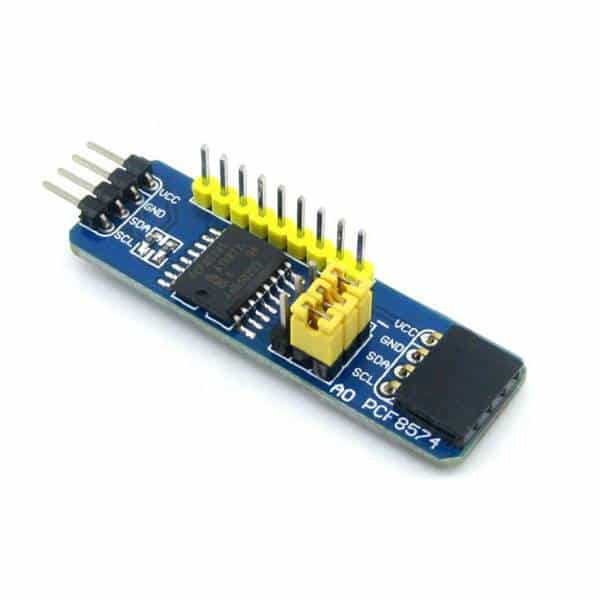
This particular device can be cascaded to provide up to 64 IO ports on the i2c bus.
At Maker and IoT Ideas, we would however like to show you electronics that you can build yourself, or stuff that have not already been made up into some kind of commercial project.
So, keeping this DIY attitude going, I will teach you how to use a shift register today.
Before we do that, we have to look at what a shift register is, and how they work…
A shift register, at its basic level, is actually just a series of D Type Flip-Flops.
These flip flops are connected together to give this
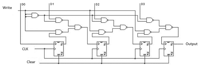
There are three basic types of Shift Register
– Serial In, Serial Out (SISO)
– Serial In, Parallel Out (SIPO) and
– Parallel In, Serial Out (PISO)
We can see that they these type of shift registers are mainly used to convert between an serial and parallel data interface.
Serial In, Serial Out ( SISO)
This is the easiest configuration for a shift register. It is basically just a row of flip flops, with the output of the first, connected to the input of the next… and so on. This type of shift register is mainly used to introduce a delay into the data stream. This means that for a 8 bit SISO Shift register, the first data will only appear at the output after 8 clock cycles !
Serial In, Parallel Out (SIPO)
This kind of Shift Register has the same configuration as the SISO type, but it differs in that there is output after every flip-flop. That makes this type of shift register a good choice to use to extend the outputs on a microcontroller like Arduino or ESP32. The downside of using a shift register as a parallel output device is that the outputs will be slightly slower than if you used the native outputs on the microcontroller.
Parallel In, Serial Out (PISO)
A Parallel In, Serial out shift register can be used to read inputs from buttons or other digital devices. These inputs are then serially shifted into a serial pin on the microcontroller to be processed. It is also slightly slower than if you used the native inputs on the microcontroller.
Universal Shift register
You are also able to use a universal shift register. These chips can be used as both inputs and outputs. They are however only available in a 4 bit configuration.
The Chips (IC’s)
| TYPE | LOGIC | CHIP NUMBER | BITS |
| SISO / SIPO | TTL | 74HC595 | 8 bit |
| SIPO | TTL | 74LS164 | 8 bit |
| PISO | TTL | 74HC166 | 8 bit |
| UNIVERSAL | TTL | 74LS194 | 4 bit |
| UNIVERSAL | TTL | 74LS195 | 4 bit |
| UNIVERSAL | CMOS | CD4035 | 4 bit |
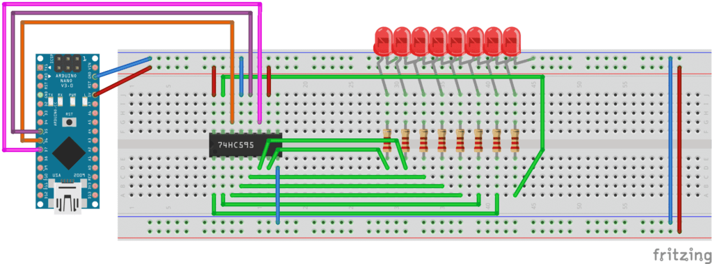
Example using Arduino with 74HC595n SIPO Shift Register
We will look at an example to connect the 74HC5959N to Arduino to drive eight (8) LEDs.
This example can be adapted to drive other loads as well by using a small BJT transistor and current limiting resistor instead of the LED
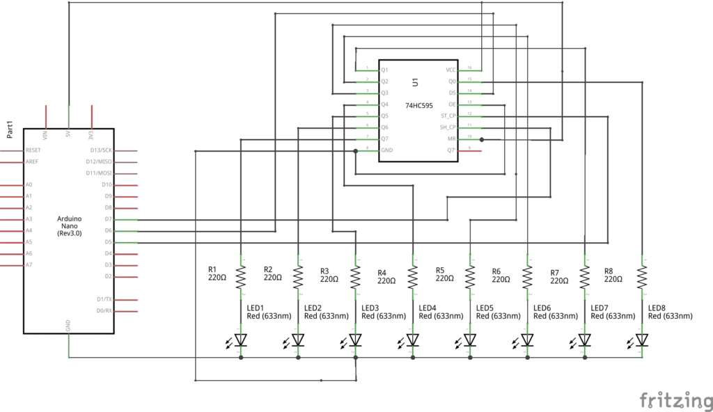
| 74hc595n Pin Number | Description and Connection |
| Q0…Q7 (15,1,2,3,4,5,6,7) | Parallel outputs of the shift register to write up to 8 signals with only 3 pins on your Arduino or ESP32 microcontroller |
| GND (8) | Connect to the ground on the microcontroller |
| VCC (16) | Connect to 3.3V or 5V on the microcontroller |
| DS (14) | Serial data input has to be connected to the microcontroller (in this example D4) |
| OE (13) | Output enable input do we not need and connected to ground |
| STCP (Latch) (12) | Storage register clock input has to be connected to the microcontroller (in this example D5) |
| SHCP (11) | Shift register clock input has to be connected to the microcontroller (in this example D6) |
| MR (10) | Master reset connected to VCC because is active with LOW and we do not want to reset the register |
| Q7S (9) | Serial data output not needed and therefore not connected |
The operation of the 74hc595n SIPO Shift Register can easily be explained in three steps:
- The latch (STCP pin) is pulled LOW because the data is only stored in the register on a LOW to HIGH transition of this pin.
- Data is shifted out to the register with the data pin (DS) and with a LOW to HIGH transition of the clock signal (SHCP).
- The latch (STCP pin) is pulled HIGH to save the data in the register.
Make the following connections to your Arduino and Breadboard ( we will use Arduino Nano today, but you can use the same pins and code for Arduino Uno )
Double-check all your connections, and then you can start the coding. The code will be much easier than you may think, as there is already a builtin function in the Arduino C language that we will use to shift the data out to the register.
// Define the Control Pins for the register
int latch-Pin = 5;
int clock-Pin = 7;
int data-Pin = 6;
void setup()
{
pinMode(latch-Pin, OUTPUT);
pinMode(data-Pin, OUTPUT);
pinMode(clock-Pin, OUTPUT);
Serial.begin(9600);
}
void loop()
{
byte leds = 0;
updateShiftRegister();
delay(1000);
for (int i = 0; i < 8; i++)
{
bitSet(leds, i);
updateShiftRegister();
for (int i = 7; i >= 0; i–)
{
bool b = bitRead(leds, i);
Serial.print(b);
}
delay(1000);
Serial.println(” “);
}
}
void updateShiftRegister()
{
digitalWrite(latch-Pin, LOW);
shiftOut(data-Pin, clock-Pin, LSBFIRST, less);
digitalWrite(latch-Pin, HIGH);
}
In this example, we output a HIGH to each led in turn, shifting from 0 to 7.
I hope that this will make sense to everybody, and be useful.
Questions and comments are welcome. Next time, we will look as using a PISO Shift register to extend the inputs on you Arduino/ESP32/STM32
Thank you.