MCP23017 with Adafruit Library

In a previous post, I have shown you how to use the MCP23017 16 Port I2C I/O Port extender with the standard Wire library, as supplied with the Arduino IDE. In this post,
I will have a quick look at using Adafruit’s library for this IC. I believe that this library brings a lot of ease-of-use to the part, making it possible to obscure some of the complexity of I2C.

I do however prefer to use the native Wire library myself, as it is slightly faster.

You can download the Adafruit MCP23017 Library from here..

Pin Addressing

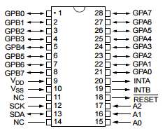
When using single pin operations such as pinMode(pinId, dir) or digitalRead(pinId) or digitalWrite(pinId, val) then the pins are addressed using the ID’s below. For example, for set the mode of GPB0 then use pinMode(8, …).

Physical Pin #Pin NamePin ID
21GPA00
22GPA11
23GPA22
24GPA33
25GPA44
26GPA55
27GPA66
28GPA77
1GPB08
2GPB19
3GPB210
4GPB311
5GPB412
6GPB513
7GPB614
8GPB715

Some examples, directly from the library, all code belongs to Adafruit, and was not written by me.

1. A Button Example

#include <Wire.h>
#include "Adafruit_MCP23017.h"

// Basic pin reading and pullup test for the MCP23017 I/O expander
// public domain!

// Connect pin #12 of the expander to Analog 5 (i2c clock)
// Connect pin #13 of the expander to Analog 4 (i2c data)
// Connect pins #15, 16 and 17 of the expander to ground (address selection)
// Connect pin #9 of the expander to 5V (power)
// Connect pin #10 of the expander to ground (common ground)
// Connect pin #18 through a ~10kohm resistor to 5V (reset pin, active low)

// Input #0 is on pin 21 so connect a button or switch from there to ground

Adafruit_MCP23017 mcp;
  
void setup() {  
  mcp.begin();      // use default address 0

  mcp.pinMode(0, INPUT);
  mcp.pullUp(0, HIGH);  // turn on a 100K pullup internally

  pinMode(13, OUTPUT);  // use the p13 LED as debugging
}


void loop() {
  // The LED will 'echo' the button
  digitalWrite(13, mcp.digitalRead(0));
}

2. An Interrupt Example

// Install the LowPower library for optional sleeping support.
// See loop() function comments for details on usage.
//#include <LowPower.h>

#include <Wire.h>
#include <Adafruit_MCP23017.h>

Adafruit_MCP23017 mcp;

byte ledPin=13;

// Interrupts from the MCP will be handled by this PIN
byte arduinoIntPin=3;

// ... and this interrupt vector
byte arduinoInterrupt=1;

volatile boolean awakenByInterrupt = false;

// Two pins at the MCP (Ports A/B where some buttons have been setup.)
// Buttons connect the pin to grond, and pins are pulled up.
byte mcpPinA=7;
byte mcpPinB=15;

void setup(){

  Serial.begin(9600);
  Serial.println("MCP23007 Interrupt Test");

  pinMode(arduinoIntPin,INPUT);

  mcp.begin();      // use default address 0
  
  // We mirror INTA and INTB, so that only one line is required between MCP and Arduino for int reporting
  // The INTA/B will not be Floating 
  // INTs will be signaled with a LOW
  mcp.setupInterrupts(true,false,LOW);

  // configuration for a button on port A
  // interrupt will triger when the pin is taken to ground by a pushbutton
  mcp.pinMode(mcpPinA, INPUT);
  mcp.pullUp(mcpPinA, HIGH);  // turn on a 100K pullup internally
  mcp.setupInterruptPin(mcpPinA,FALLING); 

  // similar, but on port B.
  mcp.pinMode(mcpPinB, INPUT);
  mcp.pullUp(mcpPinB, HIGH);  // turn on a 100K pullup internall
  mcp.setupInterruptPin(mcpPinB,FALLING);

  // We will setup a pin for flashing from the int routine
  pinMode(ledPin, OUTPUT);  // use the p13 LED as debugging
  
}

// The int handler will just signal that the int has happen
// we will do the work from the main loop.
void intCallBack(){
  awakenByInterrupt=true;
}

void handleInterrupt(){
  
  // Get more information from the MCP from the INT
  uint8_t pin=mcp.getLastInterruptPin();
  uint8_t val=mcp.getLastInterruptPinValue();
  
  // We will flash the led 1 or 2 times depending on the PIN that triggered the Interrupt
  // 3 and 4 flases are supposed to be impossible conditions... just for debugging.
  uint8_t flashes=4; 
  if(pin==mcpPinA) flashes=1;
  if(pin==mcpPinB) flashes=2;
  if(val!=LOW) flashes=3;

  // simulate some output associated to this
  for(int i=0;i<flashes;i++){  
    delay(100);
    digitalWrite(ledPin,HIGH);
    delay(100);
    digitalWrite(ledPin,LOW);
  }

  // we have to wait for the interrupt condition to finish
  // otherwise we might go to sleep with an ongoing condition and never wake up again.
  // as, an action is required to clear the INT flag, and allow it to trigger again.
  // see datasheet for datails.
  while( ! (mcp.digitalRead(mcpPinB) && mcp.digitalRead(mcpPinA) ));
  // and clean queued INT signal
  cleanInterrupts();
}

// handy for interrupts triggered by buttons
// normally signal a few due to bouncing issues
void cleanInterrupts(){
  EIFR=0x01;
  awakenByInterrupt=false;
}  

/**
 * main routine: sleep the arduino, and wake up on Interrups.
 * the LowPower library, or similar is required for sleeping, but sleep is simulated here.
 * It is actually posible to get the MCP to draw only 1uA while in standby as the datasheet claims,
 * however there is no stadndby mode. Its all down to seting up each pin in a way that current does not flow.
 * and you can wait for interrupts while waiting.
 */
void loop(){
  
  // enable interrupts before going to sleep/wait
  // And we setup a callback for the arduino INT handler.
  attachInterrupt(arduinoInterrupt,intCallBack,FALLING);
  
  // Simulate a deep sleep
  while(!awakenByInterrupt);
  // Or sleep the arduino, this lib is great, if you have it.
  //LowPower.powerDown(SLEEP_1S, ADC_OFF, BOD_OFF);
  
  // disable interrupts while handling them.
  detachInterrupt(arduinoInterrupt);
  
  if(awakenByInterrupt) handleInterrupt();
}


I hope that this shows you another way of using this versatile IC, 
In a future post, I will show you how to do interrupts, using the native Wire library, as well as point out a few things about why interrrupts sometimes does not seem to be working, as well as a workaround for that.

A Business Card with a Purpose

I recently got some inspiration from the JLCPCB User Group on Facebook. Catherine showed off her PCB style business card, and I just had to had one myself. As it is also
time to get some new cards of my own, I decided to do a PCB version, that can be handed out to very special customers, but with a twist… I added a functional Arduino Nano style
circuit to the business card, complete with microUSB port etc.

New Business Card – Front Side

My plan is to have some of these manufactured at Jlcpcb together with my next order, to save on shipping 😉 I am planning to have it done with a black soldermask, as well as real gold surface treatment.

Back of the Business card

I will leave the Gold PCB without components, or maybe have a few assembled, have not decided yet 🙂

You can get access to the entire project, in case you are also inspired to do your own
on GitHub here: https://github.com/makeriot2020/BusinessCard-Nano
or on the EasyEDA Software here: https://easyeda.com/jean.redelinghuys/bussinescard

I hope someone is inspired enough to try their own, or if you are so inclined, order some from me. If I get enough of a response, I will a standard PCB run, but with lead-free HASL 🙂

ESP32/ESP8266 WiFi Config and OTA on Demand

While working on a recent project, using a custom version of the ESP32, I had a particular need to be able to update the firmware of the device, as well as allow the end-user to set various configuration options on the device. This need can best be described as follows below:

1. The device firmware needs to be updated periodically, as new features are needed, or when bugs are discovered by the end-user, that needs fixing. The problem encountered was that the physical device will be quite far away from me, so travelling, or sending the device to and fro via post was not really an option.

Sending uncompiled firmware to the customer is a possibility, but also risky and prone to errors, as everyone is not always inclined to learn how to update firmware via USB port from an IDE, and accidental changes to code can render it unable to compile and upload in the first place.

The device also needs to run on battery power, in remote areas without connectivity. Conserving battery power is thus also a very important issue, one that prevents me from having a permanent OTA server running via WiFi.

2. The second issue was that there are certain setup parameters that needed to be set by the end-user, these include addresses and others. My initial thoughts were to implement a simple UI via UART, but that I also quickly saw that that, although very useable to me, would not appeal very much to an end-user.

These two issues, OTA and Configuration, both done through WiFi, seemed mutually exclusive as far as all the research that I have done online seemed to be concerned. To complicate it even further, the WiFi HAD to stay off when not in use.

I believe that I have developed a very neat, workable solution, that I would like to share with you today, in the hope that it will solve some problems for somebody out there, that maybe having a similar problem.

My solution makes use of a “flag” set in the ESP32/ESP8266 device’s EEPROM.
This “flag” can then be set to a “Normal” Run mode, a Firmware Update Mode, and a Configuration Mode.

Please Note: The code below has been tested, and works perfectly. You will however have to make modifications to use it for your own needs.

The code is also very long, so I will explain the operation here:

When first started, the chip will run your standard code.
When you quickly press the PGM button, 5 times after each other, a flag will be set to 0x0F.
This will then activate the ESP Soft IP.
You can then connect to this AP, and telnet to 192.168.4.1 on port 23

You will be presented with a very brief menu, where you can SET Firmware Mode, Exit or see the menu again.

This can be expanded to suit your needs

On setting Firmware Mode, the Flag 0xFF is written to EEPROM, and the ESP is restarted.
upon startup, you once more connect to the generated SoftIP, and then browse to http://192.168.4.1, log in with username admin, and password admin.

You can now load and upload a .bin firmware file to the ESP.
on successful upload, the flag 0x00 is once more written to EEPROM.

After restarting, the device will once more run your standard code.


Let us look at how I have done this:

The actual code will be commented with details, please read that for more info.

#include "EEPROM.h"
#include <WiFi.h>
#include <WiFiClient.h>
#include <WebServer.h>
#include <ESPmDNS.h>
#include <Update.h>

#define EEPROM_SIZE 64 // This can be smaller or larger, adjust to    //your needs as well as the chip capabilities
int wifi_ap_on = 0; // the address for the "flag"


// Wifi for Firmware Update and Configuration Server(s)
const char* host = "ESP32/8266";
char* ssid = "--- your desired ssid ---";
char* password = "--- your password ---";

// Define two types of Servers, they will however not run at the same // time
WebServer OTAserver(80); // OTA Server Port
WiFiServer ConfigServer(23); // Configuration Server Port

String header; // HTML requests will be stored in here

// HTML Pages for Firmware Updater
/*
 * These are the standard OTA examples that came with Arduino IDE
 * Modify and enhance as see fit, keeping in mind that my application
 * would not have access to the internet
 */

/*
 * Login page
 */
const char* loginIndex = 
 "<form name='loginForm'>"
    "<table width='20%' bgcolor='A09F9F' align='center'>"
        "<tr>"
            "<td colspan=2>"
                "<center><font size=4><b>ESP Firmware Update Page</b></font></center><br>"
                
                "<br>"
            "</td>"
            "<br>"
            "<br>"
        "</tr>"
        "<td>Username:</td>"
        "<td><input type='text' size=25 name='userid'><br></td>"
        "</tr>"
        "<br>"
        "<br>"
        "<tr>"
            "<td>Password:</td>"
            "<td><input type='Password' size=25 name='pwd'><br></td>"
            "<br>"
            "<br>"
        "</tr>"
        "<tr>"
            "<td><input type='submit' onclick='check(this.form)' value='Login'></td>"
        "</tr>"
    "</table>"
"</form>"
"<script>"
    "function check(form)"
    "{"
    "if(form.userid.value=='admin' && form.pwd.value=='admin')"
    "{"
    "window.open('/serverIndex')"
    "}"
    "else"
    "{"
    " alert('Error Password or Username')/*displays error message*/"
    "}"
    "}"
"</script>";

const char* serverIndex = "<form method='POST' action='/update' enctype='multipart/form-data'><input type='file' name='update'><input type='submit' value='Update'></form>";
// End HTML Pages 

// Other variables
int Btn = 0; // The PGM button, Usually connected to GPIO0
int wifi_ap = 0; // The Running MODE
int buttonState;
int buttonValue = 0;
int lastButtonState = LOW;
int buttoncount = 0;

void setup()
{
   Serial.begin(115200);
   EEPROM.begin(EEPROM_SIZE); initiate EEPROM
  /*
   * Upload the sketch via USB the first time, and let chip run for
   * a few seconds. We need to set the EEPROM location to a known
   * initial value. Then comment the following 3 lines, to prevent 
   * the chip from overwriting the EEPROM location on next startup
   */
  pinMode(Btn,INPUT);
  EEPROM.write(wifi_ap_on,0x00); // comment this line after first run
  EEPROM.commit();// comment this line after first run
  delay(50);// comment this line after first run
  wifi_ap = EEPROM.read(wifi_ap_on); // read EEPROM value into "flag"
  
  if (wifi_ap == 0x00) { 
   // This will be executed on normal startup
   // Place all your normal initialisation stuff here
   // For example other pin configurations and 
   // peripheral  initialisations
  } else if (wifi_ap == 0xFF) { // Firmware Update MODE
   // Setup for OTA Webserver.
   // I have used SoftAP mode, as internet would not
   // be available anyway.

    WiFi.softAP(ssid,password);
    IPAddress IP = WiFi.softAPIP();
    Serial.println("");
    Serial.print("Connected to ");
    Serial.println(ssid);
    Serial.print("IP address: ");
    Serial.println(WiFi.localIP()); 
     
    if (!MDNS.begin(host)) { //http://esp32.local
        Serial.println("Error setting up MDNS responder!");
        while (1) {
        delay(1000);
      }
    }

    
    server.on("/", HTTP_GET, []() {
    server.sendHeader("Connection", "close");
    server.send(200, "text/html", loginIndex);
  });
  server.on("/serverIndex", HTTP_GET, []() {
    server.sendHeader("Connection", "close");
    server.send(200, "text/html", serverIndex);
  });
  /*handling uploading firmware file */
  server.on("/update", HTTP_POST, []() {
    server.sendHeader("Connection", "close");
    server.send(200, "text/plain", (Update.hasError()) ? "FAIL" : "OK");
    ESP.restart();
  }, []() {
    HTTPUpload& upload = server.upload();
    if (upload.status == UPLOAD_FILE_START) {
      Serial.printf("Update: %s\n", upload.filename.c_str());
      if (!Update.begin(UPDATE_SIZE_UNKNOWN)) { //start with max available size
        Update.printError(Serial);
      }
    } else if (upload.status == UPLOAD_FILE_WRITE) {
      /* flashing firmware to ESP*/
      if (Update.write(upload.buf, upload.currentSize) != upload.currentSize) {
        Update.printError(Serial);
      }
    } else if (upload.status == UPLOAD_FILE_END) {
      if (Update.end(true)) { //true to set the size to the current progress

/*
 * NOTE : We clear the EEPROM Flag after a sucessful Firmware Update
 * That way, the chip will stay in OTA mode on a failure.
 */
        EEPROM.write(wifi_ap_on,0x00);
        EEPROM.commit();
        delay(5);
        Serial.printf("Update Success: %u\nRebooting...\n", upload.totalSize);
      } else {
        Update.printError(Serial);
      }
    }
  });
    OTAserver.begin();
  } else if (wifi_ap == 0x0F) { // End of Mode 0xFF 

    //This is Configuration Mode
    //This code will normally not be executed,
    //As the device exits Config mode on restart, and
    //We dont write Mode 0x0F to EEPROM

  } // End of Mode 0x0F
} // End of Void Setup

void loop() 
{
  CountButton(); // Count Button Presses
  if (buttoncount == 5) { // Activate Configuration Mode
    buttoncount = 0;
    StartSoftAP(); // Start a SoftAP
  }
  if (wifi_ap == 0x0F) { // Code for the Config Server (TELNET Style)
       WiFiClient client = ConfigServer.available(); // Start Config
       if (client) {
          String currentLine = "";
          client.println();
          client.println("Telnet Server - Welcome");
          client.println();
          client.println("Press <Enter> to Login");
          
    while (client.connected()) {
      if (client.available()) {
       char c = client.read();
       if (c == '\n') {
        if (currentLine.length() == 0) {
           
        } else {
          // Process Commands
       if (currentLine == "Master123abc") {
        telnetLogin == true;
        client.println();
        client.println();
        client.println("****** MENU ******");
          client.println();
          client.println("MENU -  SHOW THIS MENU");
          client.println("RUF  -  Enable Firmware Update Mode");
          client.println("EXIT -  Exit Menu and RESTART");
          client.println();
          client.print("Command> ");
          currentLine = "";
       }
       // Show MENU
       if (currentLine == "MENU") {
        client.println();
        client.println();
        client.println("****** MENU ******");
          client.println();
          client.println("MENU -  SHOW THIS MENU");
          client.println("RUF  -  Enable Firmware Update Mode");
          client.println("EXIT -  Exit Menu and RESTART");
          client.println();
          client.print("Command> ");
          
       }
 
       // EXIT AND RESTART
       if (currentLine == "EXIT") {
        client.println();
        client.println("Restarting in 5 Seconds");
        delay(5000);
        client.stop();
        ESP.restart();
      }
      // Upgrade Frmware Mode
      if (currentLine == "RUF") {
          client.println();
          client.println("Enable Firmware Update Mode");
          client.print("Connect to SoftAP :");
          client.println(ssid);
          client.println("Browse to http://192.168.4.1 ");
          client.println("Login with Username admin, Password admin");
          EEPROM.write(wifi_ap_on,0xFF); // Set Flag in EEPROM
          EEPROM.commit();
          delay(5000);
          client.stop();
          ESP.restart(); // Restart Device
      }
      
       // End Process commands 
           
          currentLine = ""; 
        }
        
       } else if (c != '\r') {
        currentLine += c;
       }  
        
      } // End if client Available
    } // End While Client Connected
    client.stop();
   } // END Client
  } // END MODE 0x0F
  if (wifi_ap == 0xFF) {
    OTAserver.handleClient(); // Handle OTA Server
    delay(1);
  }
  if (wifi_ap == 0x00 )
    // Normal code goes here , to be executed every cycle
  {

} // End of Void Loop

void StartSoftAP() // Start SoftAP, for Configuration Server
{
  WiFi.mode(WIFI_OFF);
  WiFi.softAP(ssid,password);
  IPAddress IP = WiFi.softAPIP();
  ConfigServer.begin();  
  wifi_ap = 0x0F; // Set Flag to Config Mode
                  // Note that we dont write it in EEPROM
}

void CountButton() // Counts Button Presses, to enable Config Mode
{
  //int buttonState;
  //int buttonValue = 0;
  //int lastButtonState = LOW;
  //int buttoncount = 0;
  //unsigned long lastDebounceTime = 0;
  //int debounceDelay = 50;
  buttonValue = digitalRead(Btn);
  if (buttonState != lastButtonState) {
    if (buttonValue == LOW) {
      buttoncount++;
      if (buttoncount > 10) buttoncount = 0;
    }
  }
  delay(50);
  lastButtonState = buttonValue;
  // End Debouncing
  if (buttoncount == 5) digitalWrite(LED,HIGH);
}

This concludes a very long piece of code, question are welcome.
Thank you

Using the MCP23017 to increase your GPIO’s

Today I will show you another useful IO Expander chip, The MCP23017. This chip, although similar to the PCF8475, which I have already covered in a previous article, has many additional features that may make it a very attractive solution when you need some more extra GPIO pins for a big project…

Features

Let us look at some of the features of this chip

  • 16-Bit Remote Bidirectional I/O Port:
  • I/O pins default to input
    • High-Speed I2C Interface (MCP23017):
  • 100 kHz
  • 400 kHz
  • 1.7 MHz
    • High-Speed SPI Interface (MCP23S17):
  • 10 MHz (maximum)
    • Three Hardware Address Pins to Allow Up to
    Eight Devices On the Bus
    • Configurable Interrupt Output Pins:
  • Configurable as active-high, active-low or
    open-drain
    • INTA and INTB Can Be Configured to Operate
    Independently or Together
    • Configurable Interrupt Source:
  • Interrupt-on-change from configured register
    defaults or pin changes
    • Polarity Inversion Register to Configure the
    Polarity of the Input Port Data
    • External Reset Input
    • Low Standby Current: 1 µA (max.)
    • Operating Voltage:
  • 1.8V to 5.5V @ -40°C to +85°C
  • 2.7V to 5.5V @ -40°C to +85°C
  • 4.5V to 5.5V @ -40°C to +125°C
MCP23017 Pinout Diagram

The sixteen I/O ports are separated into two ‘ports’ – A (on the right) and B (on the left. Pin 9 connects to 5V, 10 to GND, 11 isn’t used, 12 is the I2C bus clock line (Arduino Uno/Duemilanove analogue pin 5, Mega pin  21), and 13 is the I2C bus data line (Arduino Uno/Duemailnove analogue pin 4, Mega pin 20).

External pull-up resistors should be used on the I2C bus – in our examples we use 4.7k ohm values. Pin 14 is unused, and we won’t be looking at interrupts, so ignore pins 19 and 20. Pin 18 is the reset pin, which is normally high – therefore you ground it to reset the IC. So connect it to 5V!

Finally we have the three hardware address pins 15~17. These are used to determine the I2C bus address for the chip. If you connect them all to GND, the address is 0x20. If you have other devices with that address or need to use multiple MCP23017s, see figure 1-2 in the datasheet.

You can alter the address by connecting a combination of pins 15~17 to 5V (1) or GND (0). For example, if you connect 15~17 all to 5V, the control byte becomes 0100111 in binary, or 0x27 in hexadecimal.

It is also available on a convenient breakout PCB, for about $USD0.80 from AliExpress

MCP23017 on Breakout PCB – Back
MCP23017 on Breakout PCB – Front

Please Note: THIS BREAKOUT PCB IS NOT SUITED FOR USE ON A BREADBOARD. YOU WILL SHORT OUT VCC AND GROUND AS WELL AS ALL THE IO PINS IF YOU TRY TO USE IT ON A BREADBOARD.

As you can see, the pins are however very clearly labelled, and thus easy to use. I have also purposely soldered my header pins “the wrong way round” to prevent using it on a breadboard, as this will short out Vcc to Ground!

Having interrupt outputs is one of the most important features of the MCP23017, since the microcontroller does not have to continuously poll the device to detect an input change. Instead an interrupt service routine can be used to react quickly to an input change such a key press…

To make life even easier each GPIO input pin can be configured with an internal pullup (~100k) and that means you won’t have to wire up external pull up resistors for keyboard input. You can also mix and match inputs and outputs the same as any standard microcontroller 8 bit port.

Addressing

The 23017 has three input pins to allow you to set a different address for each attached MCP23017.

The above corresponds to a hardware address for the three lines A0, A1, A2 corresponding to the input pin values at the IC. You must set the value of these hardware inputs as 0V or (high) volts and not leave them floating otherwise they will get random values from electrical noise and the chip will do nothing!

The four left most bits are fixed a 0100 (specified by a consortium who doles out address ranges to manufacturers).

So the MCP23017 I2C address range is 32 decimal to 37 decimal or 0x20 to 0x27 for the MCP23017.

Please note: The addresses are the same as those for the PCF8475. You must thus be careful if you use these two devices on the same i2c bus!

MCP23017 Non interrupt registers

IODIR I/O direction register

For controlling I/O direction of each pin, register IODIR (A/B) lets you set the pin to an output when a zero is written and to an input when a ‘1’ is written to the register bit. This is the same scheme for most microcontrollers – the key is to remember that zero (‘0’) equates to the ‘O’ in Output.

GPPU Pullup register

Setting a bit high sets the pullup active for the corresponding I/O pin.

OLAT Output Latch register

This is exactly the same as the I/O port in 18F series PIC chips where you can read back the “desired” output of a port pin whether or not the actual state of that pin is reached. i.e. consider a strong current LED attached to the pin – it is easily possible to pull down the output voltage at the pin to below the logic threshold i.e. you would read back a zero if reading from the pin itself when in fact it should be a one. Reading the OLAT register bit returns a ‘one’ as you would expect from a software engineering point of view.

IPOL pin inversion register

The IPOL(A/B) register allows you to selectively invert any input pin. This reduces the glue logic needed to interface other devices to the MCP23017 since you won’t need to add inverter logic chips to get the correct signal polarity into the MCP23017.

It is also very handy for getting the signals the right way up e.g. it is common to use a pull up resistor for an input so when a user presses an input key the voltage input is zero, so in software you have to remember to test for zero.

Using the MCP23017 you could invert that input and test for a 1 (in my mind a key press is more equivalent to an on state i.e. a ‘1’) however I use pullups all the time (and uCs in general use internal pullups when enabled) so have to put up with a zero as ‘pressed’. Using this device would allow you to correct this easily.Note: The reason that active low signals are used everywhere is a historical one: TTL (Transistor Transistor Logic) devices draw more power in the active low state due to the internal circuitry, and it was important to reduce unnecessary power consumption – therefore signals that are inactive most of the time e.g. a chip select signal – were defined to be high. With CMOS devices either state causes the same power usage so it now does not matter – however active low is used because everyone uses it now and used it in the past.

SEQOP polling mode : register bit : (Within IOCON register)

If you have a design that has critical interrupt code e.g. for performing a timing critical measurement you may not want non critical inputs to generate an interrupt i.e. you reserve the interrupt for the most important input data.

In this case, it may make more sense to allow polling of some of the device inputs. To facilitate this “Byte mode” is provided. In this mode, you can read the same set of GPIOs using clocks but not needling to provide other control information. i.e. it stays on the same set of GPIO bits, and you can continuously read it without the register-address updating itself. In non-byte mode, you either have to set the address you read from (A or B bank) as control input data.

Now to examine how to use the IC in our sketches.

As you should know by now most I2C devices have several registers that can be addressed. Each address holds one byte of data that determines various options. So before using we need to set whether each port is an input or an output. First, we’ll examine setting them as outputs. So to set port A to outputs, we use:

Wire.beginTransmission(0x20);
Wire.write(0x00); // IODIRA register
Wire.write(0x00); // set all of port A to outputs
Wire.endTransmission();

Then to set port B to outputs, we use:

Wire.beginTransmission(0x20);
Wire.write(0x01); // IODIRB register
Wire.write(0x00); // set all of port B to outputs
Wire.endTransmission();

So now we are in void loop()  or a function of your own creation and want to control some output pins. To control port A, we use:

Wire.beginTransmission(0x20);
Wire.write(0x12); // address port A
Wire.write(??);  // value to send
Wire.endTransmission();

To control port B, we use:

Wire.beginTransmission(0x20);
Wire.write(0x13); // address port B
Wire.write(??);  // value to send
Wire.endTransmission();

… replacing ?? with the binary or equivalent hexadecimal or decimal value to send to the register.

To calculate the required number, consider each I/O pin from 7 to 0 matches one bit of a binary number – 1 for on, 0 for off. So you can insert a binary number representing the status of each output pin. Or if binary does your head in, convert it to hexadecimal. Or a decimal number.

So for example, you want pins 7 and 1 on. In binary that would be 10000010, in hexadecimal that is 0x82, or 130 decimal. (Using decimals is convenient if you want to display values from an incrementing value or function result).

For example, we want port A to be 11001100 and port B to be 10001000 – so we send the following (note we converted the binary values to decimal):

Wire.beginTransmission(0x20);
Wire.write(0x12); // address port A
Wire.write(204); // value to send
Wire.endTransmission();
Wire.beginTransmission(0x20);
Wire.write(0x13); // address port B 
Wire.write(136);     // value to send
Wire.endTransmission();

A complete Example

// pins 15~17 to GND, I2C bus address is 0x20
#include "Wire.h"
void setup()
{
 Wire.begin(); // wake up I2C bus
// set I/O pins to outputs
 Wire.beginTransmission(0x20);
 Wire.write(0x00); // IODIRA register
 Wire.write(0x00); // set all of port A to outputs
 Wire.endTransmission();
Wire.beginTransmission(0x20);
 Wire.write(0x01); // IODIRB register
 Wire.write(0x00); // set all of port B to outputs
 Wire.endTransmission();
}
void binaryCount()
{
 for (byte a=0; a<256; a++)
 {
 Wire.beginTransmission(0x20);
 Wire.write(0x12); // GPIOA
 Wire.write(a); // port A
 Wire.endTransmission();
Wire.beginTransmission(0x20);
 Wire.write(0x13); // GPIOB
 Wire.write(a); // port B
 Wire.endTransmission();
 }
}
void loop()
{
 binaryCount();
 delay(500);
}

Using the pins as inputs

Although that may have seemed like a simple demonstration, it was created show how the outputs can be used. So now you know how to control the I/O pins set as outputs. Note that you can’t source more than 25 mA of current from each pin, so if switching higher current loads use a transistor and an external power supply and so on.

Now let’s turn the tables and work on using the I/O pins as digital inputs. The MCP23017 I/O pins default to input mode, so we just need to initiate the I2C bus. Then in the void loop() or other function all we do is set the address of the register to read and receive one byte of data.

// pins 15~17 to GND, I2C bus address is 0x20
#include "Wire.h"
byte inputs=0;
void setup()
{
 Serial.begin(9600);
 Wire.begin(); // wake up I2C bus
}
void loop()
{
 Wire.beginTransmission(0x20);
 Wire.write(0x13); // set MCP23017 memory pointer to GPIOB address
 Wire.endTransmission();
 Wire.requestFrom(0x20, 1); // request one byte of data from MCP20317
 inputs=Wire.read(); // store the incoming byte into "inputs"
 if (inputs>0) // if a button was pressed
 {
 Serial.println(inputs, BIN); // display the contents of the GPIOB register in binary
 delay(200); // for debounce
 }
}

Other Libraries

You can also download and install the MCP23017 Library from Adafruit for the Arduino IDE.
This library will make using this chip even easier… I will discuss this library in another post

I hope this will be useful to somebody.

Using I2C with a 4×4 Matrix Keypad

Using a matrix keypad is a very easy way to add multiple control buttons to a project, be it to enter a password, or to control different devices. These keypads do unfortunately have some serious flaws (in my view anyway)

1) They are usually of extremely low quality ( especially some of the membrane types from China). This means they dont last very long.
2) A typical 4×4 Matrix keypad will require 8 of your precious IO pins for itself.

These two flaws can however easily be solved, if we use a bit of technology, and are willing to to a bit of simple circuit construction by ourselves.

What does this mean ? Most of us makers will inevitably have a piece of proto-board or strip-board lying around, as well as a few momentary push-button switches. These can easily be used to make out own, much more reliable keypad. Let us look at the circuit

Circuit diagram for a 4×4 Matrix Keypad

As we can see, to build a 4×4 matrix keypad, we will need 16 momentary switches. These are connected together as shown above. You can then interface it with your favourite micro-controller to read the key(s) pressed…

This definitely solves the first of my problems, but we still need 8 pins to control this keypad… or do we? No, we don’t, we need only 2 pins. That is to say if we use one of those PCF8574 I2C IO port expander modules. They are much more reliable, as well as quite cheap as well. all depending on where you buy them from, and how long you are willing to wait for shipping 🙂

Let us see how to connect the keypad to the I2C Module

a 4×4 Membrane Matrix Keypad with PCF8574 I2C port expander module
Connecting the two together, note that we do not connect the INT pin
Connect Power (VCC, GND and I2C lines
Connect to Arduino or your preferred microcontroller. We have used Arduino Uno, Note that you can also connect the I2C to A4 (SDA) and A5(SCL) if you prefer.

Now, we need to install some libraries

The first one is the actual Keypad library, you can download it from the link below

The second library that we will need, is the keypad_i2c library, once again, download it from the link below.

Coding the keypad


#include <Key.h>
#include <Keypad.h>
#include <Keypad_I2C.h>

#define I2CADDR 0x26 // Set the Address of the PCF8574

const byte ROWS = 4; // Set the number of Rows
const byte COLS = 4; // Set the number of Columns

// Set the Key at Use (4x4)
char keys [ROWS] [COLS] = {
  {'1', '2', '3', 'A'},
  {'4', '5', '6', 'B'},
  {'7', '8', '9', 'C'},
  {'*', '0', '#', 'D'}
};

// define active Pin (4x4)
byte rowPins [ROWS] = {0, 1, 2, 3}; // Connect to Keyboard Row Pin
byte colPins [COLS] = {4, 5, 6, 7}; // Connect to Pin column of keypad.

// makeKeymap (keys): Define Keymap
// rowPins:Set Pin to Keyboard Row
// colPins: Set Pin Column of Keypad
// ROWS: Set Number of Rows.
// COLS: Set the number of Columns
// I2CADDR: Set the Address for i2C
// PCF8574: Set the number IC
Keypad_I2C keypad (makeKeymap (keys), rowPins, colPins, ROWS, COLS, I2CADDR, PCF8574);

void setup () {
  Wire .begin (); // Call the connection Wire
  keypad.begin (makeKeymap (keys)); // Call the connection
  Serial.begin (9600);

}
void loop () {
 
  char key = keypad.getKey (); // Create a variable named key of type char to hold the characters pressed
 
  if (key) {// if the key variable contains
    Serial.println (key); // output characters from Serial Monitor
  }
}

Upload this to your Arduino device and enjoy. This sketch can also be adapted for 1×4, and 4×3 keypads, and with a little modification, will also work perfectly on ESP32 or ESP8266 as well…

ESP8266 and ESP32 AT Commands

NodeMCU V3, ESP8266

In this tutorial, I’ll show you some of the important and frequently used ESP8266 AT Commands or AT Instruction Set.  

ESP8266 WiFi Module offers complete networking solutions to our DIY (Do-it-yourself) and IoT (Internet of Things) projects. It provides WiFi connectivity to any microcontroller through its full TCP/IP Stack.

This means that you can use the ESP8266/ESP32 like a WiFi Modem, this is especially handy when you don’t want to reprogram an entire module for a project, or if you already have a working project on an Arduino type board, and just want to add WiFi connectivity to the project.


It is however important to tell you that it is sometimes better to write your own code to achieve exactly what you want. The AT Commands, in my opinion, is however extremely useful to quickly test something, or do a very simple integration. Your opinion and or milage will definitely vary on this one, feel free to comment and make suggestions as always 🙂

Kidbright 32, based on the ESP32 WROOM Chip

Let us get started then

Please NOTE:

The AT Command Set will ONLY function on a NEW ESP8266/ESP32 Module that you have not loaded custom firmware onto, OR on a module that you have re-flashed with the AT Command Firmware. This means that, If you have used the Arduino IDE to upload custom code to your ESP8266/ESP32 module, these commands will NOT work for you,
UNLESS you flash the module with ESPRESSIF AT Command Firmware!

The ESP8266 WiFi module and the microcontroller can be interfaced through the UART and with the help of a wide range of AT Commands, the Microcontroller can then control the ESP Module.

The AT Commands of the ESP8266 WiFi Module are responsible for controlling all the operations of the module like restarting, connecting to WiFi, changing the mode of operation and so forth.

Basically, the ESP8266 AT Commands can be classified into four types:

  • Test
  • Query
  • Set
  • Execute

In the following table, I will give you an example of the different types of AT Commands. I will use a sample command of “TEST” to demonstrate the differences between the different type of commands.

Command TypeCommand FormatCommand Function
TestAT+TEST=?Returns a value or a range of parameters
QueryAT+TEST?Returns the current value of a certain parameter
SetAT+TEST=parameter1, parameter2, …Set configuration of a certain parameter of group of parameters
ExecuteAT+TESTExecutes an action
Types of AT Commands for ESP8266 or ESP32

Test Commands: The Test AT Commands of ESP8266 WiFi Module are used to get the parameters of a command and their range.

Query Commands: The Query Commands returns the present value of the parameters of a command.

Set Commands: The Set Commands are used set the values of the parameters in the commands and also runs the commands.

Execute Commands: The Execute Commands will run the commands without parameters.  

NOTE: Not all of the ESP8266 AT Commands support all the four command types.

The ESP8266 AT Commands Set is divided into three categories. They are:

  • Basic AT Commands 
  • WiFi AT Commands 
  • TCP/IP AT Commands 

There are a total of 88 AT Commands for ESP8266 WiFi Module. We will however only look at a few of the most important ones.

If you want to know the details of all the ESP8266 AT Commands, then I suggest that you visit the official documentation page provided by Espressif Systems (the manufacturer of ESP8266EX SoC),  here.   

NOTE: The Parameters mentioned in [] are optional.

Basic ESP8266 AT Commands

As per the official documentation from Espressif Systems, there are a total of 23 Basic AT Commands.

Basic AT Commands
AT
AT+RST
AT+GMR

AT

This is the basic command that tests the AT start up i.e. if the AT System is working correctly or not. If the AT start up is successful, then the response is OK.

CommandResponse
ATOK

AT+RST

This command can be used to restart (reset) the ESP8266 WiFi Module.    

CommandResponse
AT+RSTOK

AT+GMR

This command is used to check the version information of the firmware and SDK. The response consists of three things: the AT Firmware version, the SDK version and the compilation time of the BIN file.

CommandResponse
AT+GMR<AT Version><SDK Version><Compile Time>OK

Other important Basic AT Commands: AT+GSLP, ATE and AT+UART.

WiFi AT Commands

The WiFi AT Commands are useful in controlling the WiFi features of the ESP8266 Module like setting up the WiFi Mode of operation, get the list of WiFi Networks, connect to a WiFi Network, setup the Access Point (AP), control DHCP, WPS, MAC Address, IP Address etc.

As per the official documentation, there are 40 WiFi AT Commands for ESP8266 Module. Let me introduce a few important AT Commands.

WiFi AT Commands
AT+CWMODE
AT+CWJAP
AT+CWLAP
AT+CWQAP
AT+CIPSTA
AT+CWSAP
AT+CWLIF

AT+CWMODE

This command is used to set the WiFi Mode of operation as either Station mode, Soft Access Point (AP) or a combination of Station and AP. The CWMODE command supports Test, Query and Set type commands.

The syntax, response and parameters (in Set command) of this command are given in the following table.

AT+CWMODE
Command TypeTestQuerySet
FormatAT+CWMODE=?AT+CWMODE?AT+CWMODE=<mode>
Response+CWMODE:<mode>OK+CWMODE:<mode> OKOK
Parameters<mode>1: Station2: Soft Access Point (AP)3: Station+SoftAP
Function Returns current WiFi ModeSets WiFi Mode
      

AT+CWLAP

This command lists out all the available WiFi Networks in the reach of ESP8266. It has both Set and Execute Command types.

AT+CWLAP
Command TypeSetExecute
FormatAT+CWLAP[=<ssid>,<mac>,<channel>,<scan_type>,<scan_time_min>,<scan_time_max>]AT+CWLAP
Response+CWLAP:<ecn>,<ssid>,<rssi>,<mac>,<channel>,<freq      offset>,<freq   cali>,<pairwise_cipher>,<group_cipher>,<bgn>,<wps>OK

NOTE: For more information on Parameters, please refer to the original documentation.

AT+CWJAP

This command is to connect to an Access Point (like a router).

AT+CWJAP
Command TypeQuerySet
FormatAT+CWJAP?AT+CWJAP=<ssid>,<pwd>[,<bssid>]
Response+CWJAP:<ssid>,<bssid>,<channel>,<rssi>OKOKor+CWJAP:<error>FAIL
Parameters<ssid>: SSID of the Access Point.<pwd>: Password.[<bssid>]: MAC Address of AP (usedwhen multiple APs have the same SSID.)<error>1: Connection timeout.2: Wrong password.3: Cannot find the target AP.4: Connection failed.

AT+CWQAP

This command is used to disconnect the ESP8266 from an Access Point.

CommandResponse
AT+CWQAPOK

AT+CIPSTA

This command is used to set a static IP Address to the ESP8266 WiFi Module in Station Mode. This command has both Query and Set type commands.

AT+CIPSTA
Command TypeQuerySet
FormatAT+CIPSTA?AT+CIPSTA=<ip>[,<gateway>,<netmask>]
Response+CIPSTA:<ip>+CIPSTA:<gateway>+CIPSTA:<netmask> OKOK
Parameters<ip>: IP Address<gateway>: Gateway<netmask>: Netmask
FunctionReturns the IP address, Gateway and Netmask.Sets IP Address, Gateway and Netmask.

AT+CWSAP

This command is used to configure the ESP8266 WiFi Module in Soft Access Point (AP) Mode. Both Query and Set types are available for this command.

AT+CWSAP
Command TypeQuerySet
FormatAT+CWSAP?AT+CWSAP =<ssid>,<pwd>,<chl>,<ecn>[,<maxconn>][,<ssid  hidden>]
Response+CWSAP:<ssid>,<pwd>,<chl>,<ecn>,<max conn>,<ssid hidden>OKorERROR
Parameter<ssid>: SSID of AP.<pwd>: Password.<chl>: Channel ID.<ecn>: Encryption method.0: OPEN2: WPA_PSK3: WPA2_PSK4: WPA_WPA2_PSK<max conn>: Max # of Stations<ssid hidden>:0: SSID is broadcasted. (default)1: SSID is not broadcasted.

AT+CWLIF

Using this command, you can get the IP addresses of Stations that are connected to ESP8266, which is configured in SoftAP Mode.

AT+CWLIF
Format (Execute Command)AT+CWLIF
Response<ip addr>,<mac>OK
Parameters<ip address>: IP Address of the Station<mac>: MAC Address of the station

TCP/IP AT Commands

The TCP/IP AT Commands are responsible for communication over the internet. There are a total of 25 TCP/IP AT Commands for ESP8266 WiFi Module. Some of the important ones are mentioned here.

TCP/IP Commands
AT+CIPSTATUS
AT+CIPSTART
AT+CIFSR
AT+CIPMUX
AT+CIPSERVER
AT+CIUPDATE

AT+CIPSTATUS

This TCP/IP AT Command of the ESP8266 WiFi Module get the information or status of the connection. Only the Execute type command is available.

AT+CIPSTATUS
Command TypeExecute
FormatAT+CIPSTATUS
ResponseSTATUS:<stat>+CIPSTATUS:<linkID>,<type>,<remoteIP>,<remoteport>,<localport>,<tetype>
Parameter<stat>:2: Connected to an AP and its IP is obtained.3: Created a TCP or UDP transmission.4: Disconnected.5: Does NOT connect.<linkID>: ID of the connection.<type>: “TCP” or “UDP”.<remoteIP>: Remote IP address.<remoteport>: Remote port number.<localport>: Local port number.<tetype>:0: Client.1: Server.

AT+CIPSTART

This AT Command is used to establish one of the three connections: TCP, UDP or SSL. Depending on the type of TCP Connection (single or multiple), the format of the Set command will vary.

AT+CIPSTART
Command TypeSet
FormatSingle TCP ConnectionMultiple TCP Connection
AT+CIPSTART=<type>,<remoteIP>,<remoteport>[,<TCPkeepalive>]AT+CIPSTART=<linkID>,<type>,<remoteIP>,<remoteport>[,<TCPkeepalive>]
ResponseOKorERROR(Response when TCP connection is already established:ALREADY CONNECTED)
Parameters<link    ID>: ID of connection.<type>: “TCP”, “UDP” or “SSL”.<remoteIP>: Remote IP address.<remoteport>: Remote port number.[<TCPkeepalive>]: detection time interval

NOTE: The above table shows command for only establishing the TCP Connection. For establishing UDP and SSL Connections, please refer to the official documentation.

AT+CIFSR

This AT Command is used to obtain the IP Address of the ESP8266 WiFi Module.

AT+CIFSR
Command TypeExecute
FormatAT+CIFSR
Response+CIFSR:APIP,<SoftAPIPaddress>+CIFSR:APMAC,<SoftAPMACaddress>+CIFSR:STAIP,<StationIPaddress>+CIFSR:STAMAC,<StationMACaddress>OK
Parameters<SoftAPIPaddress>: IP address of the ESP8266 SoftAP;<SoftAPMACaddress>: MAC address of the ESP8266 SoftAP<StationIPaddress>: IP address of the ESP8266 Station.<StationMACaddress>: MAC address of the ESP8266 Station

AT+CIPMUX

This AT Command is used to enable or disable multiple TCP Connections.

AT+CIPMUX
Command TypeQuerySet
FormatAT+CIPMUX?AT+CIPMUX=<mode>
Response+CIPMUX:<mode>OKOK
Parameters<mode>:0: Single connection1: Multiple connections

AT+CIPSERVER

This AT Command is used to create or delete a TCP Server.

AT+CIPSERVER
Command TypeSet
FormatAT+CIPSERVER=<mode>[,<port>]
ResponseOK
Parameters<mode>:0: Delete Server.1: Create Server.

NOTE: A TCP Server can be created only when AT+CIPMUX=1 i.e. multiple connections are enabled.

AT+CIUPDATE

This AT Command is used update the software through WiFi Connection i.e. for over the air (OTA) updates.

AT+CIUPDATE
Command TypeExecute
FormatAT+CIUPDATE
Response+CIPUPDATE:<n>OK
Parameters<n>:
1: Find the Server
2: Connect to the Server
3: Get the Software Version
4: Start Update

I have included a PDF file with the complete AT command Set for download below.