
Last month I spent quite a lot of time on expansion modules for use with the ESP-12E I2C Base Card. While the system worked exceptionally well as a prototyping and firmware testing platform ( as originally intended ), I immediately saw that the physical size of everything ( base board, with the cards) would be a problem inside any enclosure, when used with a real-world project.
At the same time, I have an ongoing need to design and manufacture a device for a friend, that will have very limited space inside the enclosure due to other essential components.
I have thus decided to combine the functionality of two of the IO Expander cards into a more compact design, on a single PCB ( Which I plan to use to power and control an Air Assist blower on my desktop CNC/Laser cutter, as well as function as a next step prototype for my other project.

The PCB
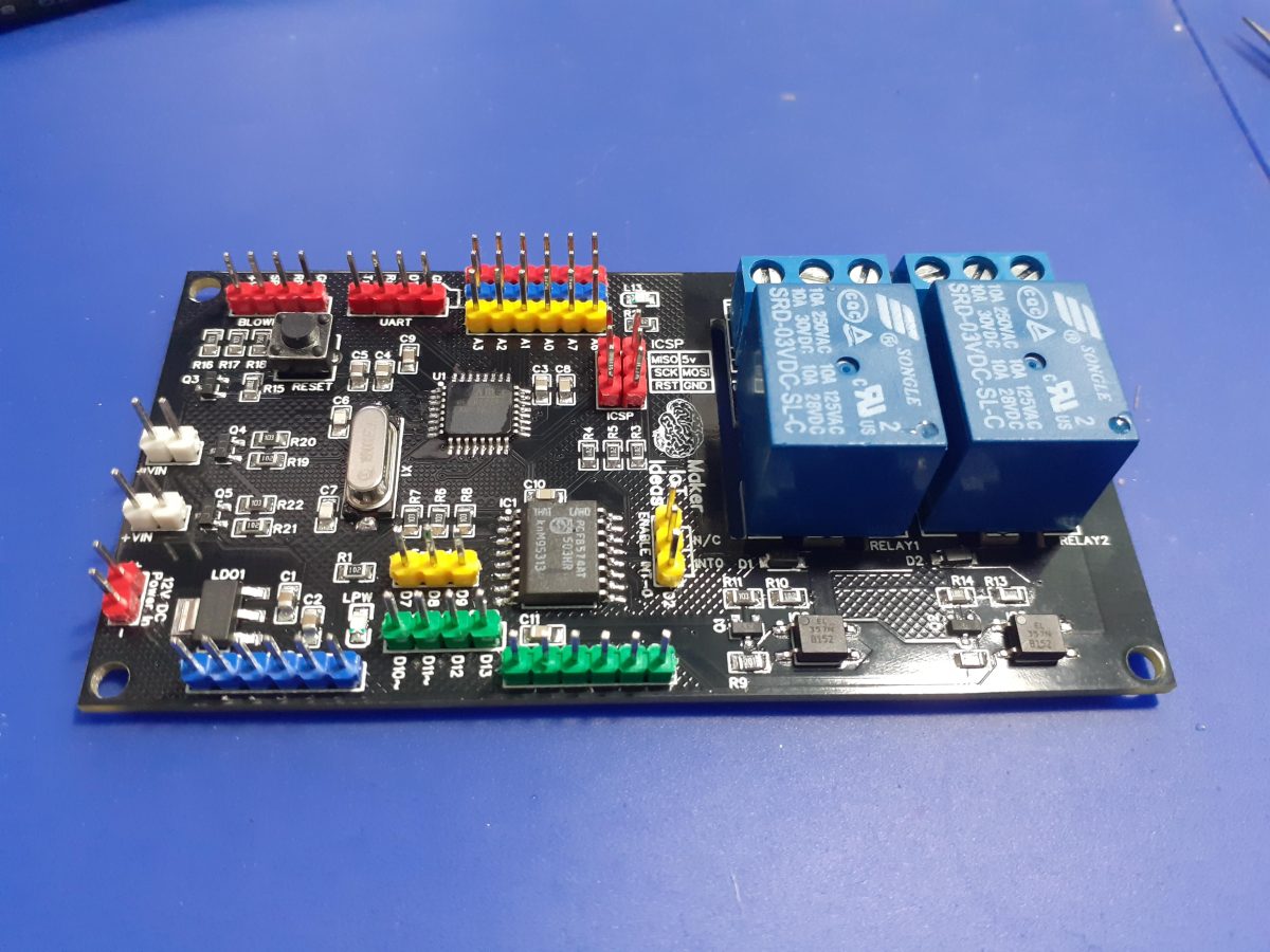
Let us take a quick look at the PCB.
Starting from the top left, we have the Blower/Fan Header.
This supplies 12v DC to the Blower/Fan motor, as well as the PWM signal to control the speed. ( Level converted up from 5v DC to 12V, and then reduced to 3.3v ) This may seem strange.
Let me explain for some more clarity…
The PWM input on the Blower/Fan is internally pulled HIGH to 12v ( by the motor driver circuitry – I can not change that, as it is a commercial unit.) The datasheet however calls for a 0v to 3.3v PWM signal to control the speed.
There is also a further input from the fan, which is a pulsed speed indicator (Fan RPM). This signal is 5v.
Next to that header, is a UART Header, with Rx, Tx and DTR signals, with a ground. I do no longer add USB-to-UART chips to my designs because they are not used a lot, take up unnecessary space, and I tend to program with ICSP anyway.
On the right of that, (Red/Blue/Yellow Header) are 5v, Gnd and 6 Analog inputs(A0-A3, A6,A7) [A4 and A5 being used for I2C]
The ICSP programming header is below that,
with a jumper to select PCF8574 interrupt on Pin D2 or not
This is followed by 6 GPIO (P2-P7) from the IO Expander, and
additional GPIO (D10, D11, D12, D13) , as well as (D7,D8,D9) [To be used with a Rotary Encoder]
Another 6way Ground header, as well as the 12v input (red), follows.
Finally, we have J1 and J2, which will switch 12v through BSS138 Mosfets to control static speed 12v cooling Fans (Only one of these is PWM capable)

The 2 Relays are optically isolated from the controller and mains isolation cutouts are provided to further keep DC and AC voltages well away from each other. [ they really don’t play well together, don’t they ?]
This wraps up the quick PCB description.
Schematic
The Schematic is below, along with a download link ( zip format, with PNG image files)


Some more pictures


I use stencils with almost all of my SMD assembly. It saves a lot of time, makes for even solder paste application, and prevents the mess associated with applying solder paste with a syringe, or even worse a skewer-stick or something similar. They do cost extra though, but I find it well worthwhile in comparison to the mess and time that they save.
Manufacturing
Over the past eight years, PCBWay has continuously upgraded their MANUFACTURING plants and equipment to meet higher quality requirements, and now THEY also provide OEM services to build your products from ideas to mass production and access to the market.
The PCB for this project has been manufactured at PCBWay.
Please consider supporting them if you would like your own copy of this PCB, or if you have any PCB of your own that you need to have manufactured.

If you would like to have PCBWAY manufacture one of your own, designs, or even this particular PCB, you need to do the following…
1) Click on this link
2) Create an account if you have not already got one of your own.
If you use the link above, you will also instantly receive a $5 USD coupon, which you can use on your first or any other order later. (Disclaimer: I will earn a small referral fee from PCBWay. This referral fee will not affect the cost of your order, nor will you pay any part thereof.)
3) Once you have gone to their website, and created an account, or login with your existing account,

4) Click on PCB Instant Quote

5) If you do not have any very special requirements for your PCB, click on Quick-order PCB

6) Click on Add Gerber File, and select your Gerber file(s) from your computer. Most of your PCB details will now be automatically selected, leaving you to only select the solder mask and silk-screen colour, as well as to remove the order number or not. You can of course fine-tune everything exactly as you want as well.


7) You can also select whether you want an SMD stencil, or have the board assembled after manufacturing. Please note that the assembly service, as well as the cost of your components, ARE NOT included in the initial quoted price. ( The quote will update depending on what options you select ).

8) When you are happy with the options that you have selected, you can click on the Save to Cart Button. From here on, you can go to the top of the screen, click on Cart, make any payment(s) or use any coupons that you have in your account.
Then just sit back and wait for your new PCB to be delivered to your door via the shipping company that you have selected during checkout.