
Adding a bit of automation to a certain area of the house can definitely help with saving energy. With this Simple Smart Light Controller, I aimed to do just that… Let me give you a tiny bit of context… Houses in SE Asia are built to some “questionable” standards and designs, and electrical installations are usually even more suspect… Our house is no exception. Being a rental, I do not want to go and make changes unless things are outright dangerous… Kitchens are usually a mixture of inside/outside areas, and this is where my device fits in…
The light in the outside kitchen consists of a simple bulb that the owner has routed into the house via an electrical flex cord, at least that was standard… But, due to laziness or just whatever, that cord was never terminated into a proper switch… He just added a plug. This is thus my opportunity to make life a bit easier for myself in that area. I could have opted for a standard switch, but then, automating this can take care of another problem… We constantly forget to switch that light off, as the plug is in a “strange place” that is not usually associated with the kitchen lights…

What I have thus come up with is a simple ESP8266-based solution with a single relay ( optically isolated from the board), as well as a few additional GPIO pins, just in case I want to hang some additional sensors onto this in the future.
The device should also be powered directly from the mains, as adding another external AC to DC adapter would definitely NOT do at all!
What is on the PCB

Lets look at the empty PCB, in order to understand better what is where on the board.
Starting on the Left Side, at the bottom corner, we have our mains voltage input, 220V or 110V, depending on where you live. That goes directly into U1, which is a AC-to-DC converter, providing 3.3v at 1A to the board. Note that I did not place a fuse directly on the board. I prefer to have an inline fuse on the line, which is also accessible from the enclosure.
A series of cutouts on the PCB provides additional mains isolation and also prevents mains voltage tracking towards other tracks in the event of a fault.
The Mains area also does not have a copper pour.
In the top left corner, towards the center, is a WAKE jumper. This is connected to GPIO16 and can be used to wake the ESP8266 from “deep sleep” if configured in the firmware.
Relay K1, and its screw terminal connector is in the bottom center of the board, with the relay contacts clearly labelled.
On the right of the PCB, we have the programming header, complete with Auto Flash and Reset circuitry, as well as manual Flash and Reset Buttons below that.
A 3×3 header connector follows, with access to 3.3v, Ground as well as 3 additional GPIO pins for other applications.
Finally, we have the relay control switch, with a few options to connect external switches, either on the 2.54mm header, or via wires soldered to the pads marked SW-A and SW-B
The populated PCB will thus make more sense if we look at the picture above now since we had a detailed look at it above…
The Schematic is made available at the link above.
Configuration and Software
This build was designed with ESPHome in mind, so we will focus on that there.
You can however very easily use standard Arduino/ESP8266 code to control this as well…
The YAML configuration for the device will be as follows: (note that this is quite simplified, as I am still fine-tuning the actual features that I require)
esphome:
  name: smart-switch-01
  friendly_name: SMART-SWITCH-01

esp8266:
  board: nodemcuv2
  restore_from_flash: true

# Enable logging
logger:

# Enable Home Assistant API
api:
  encryption:
    key: "hfYNn8KSbVq26rGkPOJo4yLj/d/WY7Hk0H3TmxlWZAU="

ota:
  password: "85ed2a8afcd61d0f4c65db7b92bdacc5"

wifi:
  ssid: !secret wifi_ssid
  password: !secret wifi_password

  # Enable fallback hotspot (captive portal) in case wifi connection fails
  ap:
    ssid: "Smart-Switch-01 Fallback Hotspot"
    password: "XovAx4n1H1qT"

captive_portal:

text_sensor:
  - platform: wifi_info
    ip_address:
      name: IP Address
    ssid:
      name: SSID
    bssid:
      name: BSSID
    mac_address:
      name: Wifi MAC
    scan_results:
      name: WiFi Scan Results


sensor:
  - platform: adc
    pin: VCC
    name: "ESP8266 Chip Voltage"
    id: mcu_voltage
    unit_of_measurement: "V"
    device_class: "voltage"
    accuracy_decimals: 2
    update_interval: 60s
    entity_category: "diagnostic"

  - platform: wifi_signal
    name: "WiFi Signal Sensor"
    id: wifi_strength
    device_class: "signal_strength"
    unit_of_measurement: "dBm"
    update_interval: 240s
    entity_category: "diagnostic"

  - platform: copy # Reports the WiFi signal strength in %
    source_id: wifi_strength
    name: "WiFi Signal Strength"
    filters:
      - lambda: return min(max(2 * (x + 100.0), 0.0), 100.0);
    unit_of_measurement: "%"
    entity_category: "diagnostic"


light:
 # - platform: status_led
 #   pin: GPIO13
 #   id: status_indicator
 #   name: "ID Light"

  - platform: binary
    name: "Kitchen Outside Light"
    output: relay_01
    id: kitchen_light
    on_turn_on:
    - light.turn_on:
        id: slow_light
        effect: "Slow Pulse"


    on_turn_off:
    - light.turn_off: slow_light


  - platform: monochromatic
    id: slow_light
    output: light_status
    restore_mode: RESTORE_AND_OFF
    effects:
      - pulse:
          name: "Slow Pulse"
          # transition_length: 1s      # defaults to 1s
          update_interval: 2s

binary_sensor:
  - platform: gpio
    pin:
      number: GPIO5
      mode:
        input: true
        pullup: true
    id: kitchen_light_toggle
    filters:
      - delayed_on: 200ms
      - delayed_off: 200ms
    on_press:
      then:
        - light.toggle: kitchen_light
  - platform: status
    name: "Kitchen Light Controller"

switch:
  - platform: restart
    name: "Restart Device"

# Relay output
output:
  - platform: gpio
    id: relay_01
    pin: GPIO4
    inverted: true
  - platform: esp8266_pwm
    id: light_status
    pin: GPIO12
Manufacturing the PCB
I choose PCBWay for my PCB manufacturing. Why? What makes them different from the rest?
PCBWay‘s business goal is to be the most professional PCB manufacturer for prototyping and low-volume production work in the world. With more than a decade in the business, they are committed to meeting the needs of their customers from different industries in terms of quality, delivery, cost-effectiveness and any other demanding requests. As one of the most experienced PCB manufacturers and SMT Assemblers in China, they pride themselves to be our (the Makers) best business partners, as well as good friends in every aspect of our PCB manufacturing needs. They strive to make our R&D work easy and hassle-free.
How do they do that?
PCBWay is NOT a broker. That means that they do all manufacturing and assembly themselves, cutting out all the middlemen, and saving us money.
PCBWay’s online quoting system gives a very detailed and accurate picture of all costs upfront, including components and assembly costs. This saves a lot of time and hassle.
PCBWay gives you one-on-one customer support, that answers you in 5 minutes ( from the Website chat ), or by email within a few hours ( from your personal account manager). Issues are really resolved very quickly, not that there are many anyway, but, as we are all human, it is nice to know that when a gremlin rears its head, you have someone to talk to that will do his/her best to resolve your issue as soon as possible.
Find out more here

Assembly and Testing
This device does not need a stencil for assembly, but using one will definitely speed up things. I chose to do this build all by hand, from applying solder-paste, up to placing components.
Soldering was done on a hotplate, as usual, to reflow everything at the same time. TH components were then placed and hand-soldered.
Uploading the initial firmware, after adding the device to ESPHome was done with an external USB-to-UART converter. All further firmware changes were made via OTA.


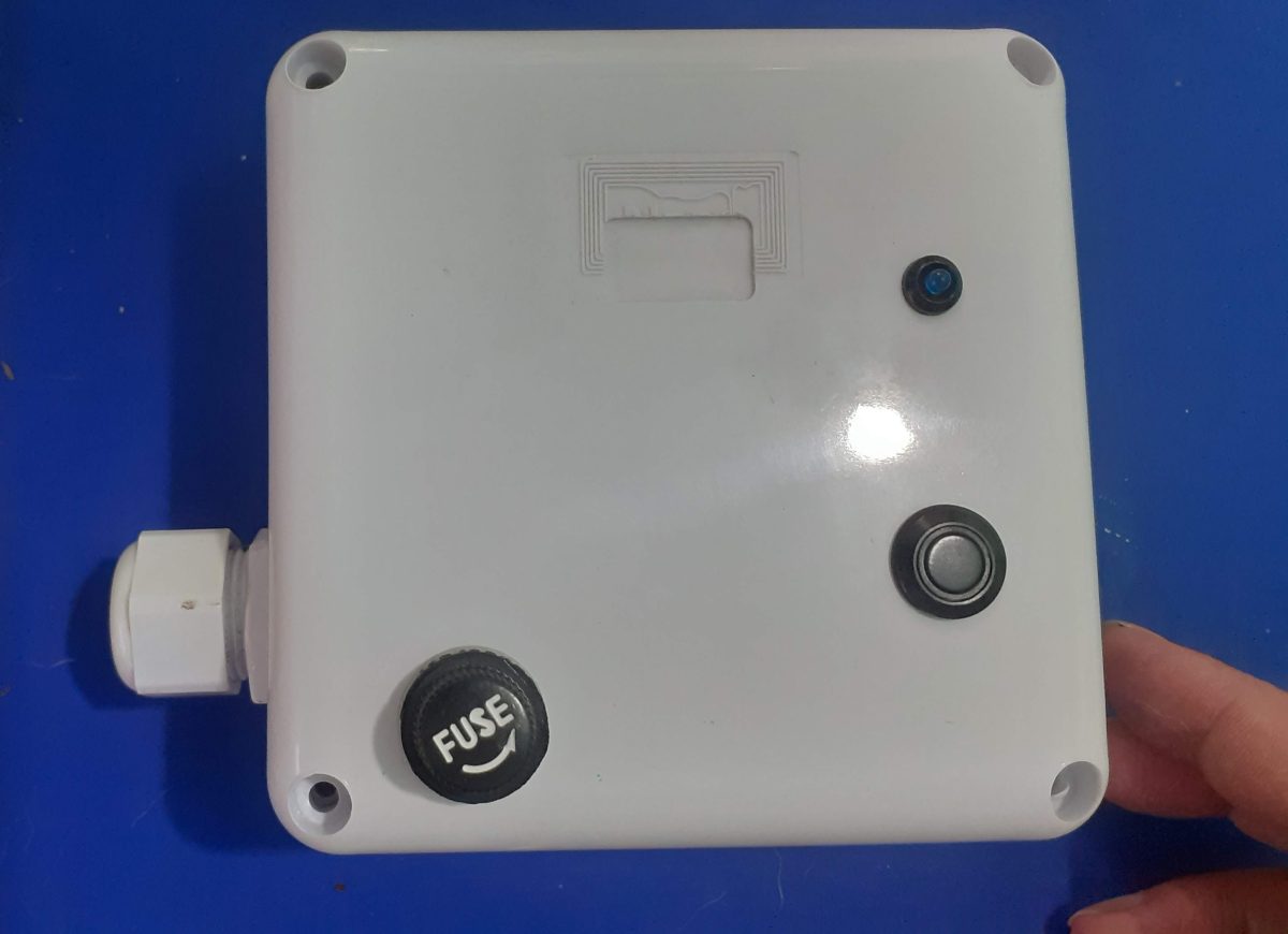
It is important to mention here that this PCB is powered by mains voltage. I chose to use an inline fuse, BEFORE the connector on the PCB. It is also notable that the relay common is connected to the live wire, BEFORE the fuse, as the lightbulb acts as its own fuse – it blows when a fault occurs.
The Lightbulb neutral will be connected to the circuit breaker, together with the device live and neutral.
This way, the fuse only acts on the actual device, and I can use a lower-rating fuse, since I do not have to accommodate the current from the lightbulb as well…
Summary
The device works as planned, with no problems…
Below is some pictures from it in Home Assistant

