
The Assembly of the ATTiny1616 Can Bus Controller PCB will be covered in this post. This PCB took quite a bit of time, due to having a real-world job that takes up an extreme amount of my time.
Enough of that, let’s get started
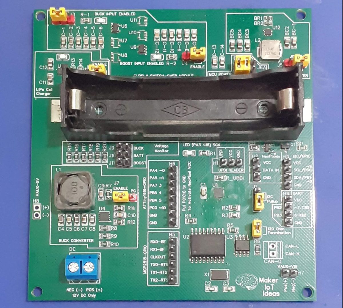
The PCB

The PCB is a double layer, with mostly SMD components, and as mentioned in the initial post, broken up into functional blocks to make testing easier. I will also take the time to mention some performance and problem issues that I have encountered during the testing phase here are well
These include:
– a buck converter power supply module to provide 5v DC.
– a single-cell lipo cell charger circuit
– an ideal diode supply or-ing circuit
– a boost converter
– various jumpers, so enable/disable certain parts of the circuit
– microcontroller and logic circuits

All of the circuit modules mentioned have been covered in detail in previous posts, so I will only briefly review some of them here to highlight some changes I have made to the original circuits.
The ideal diode supply or-ing circuit has been modified to use 3 ideal diode chips in parallel per “channel”. This is “experimental” from my point of view since I am unsure if it would actually perform as expected. I had to do this due to experiencing great difficulty in obtaining a suitable high-current component at a reasonable cost and in a suitable footprint.
This question remains unanswered, as I encountered a double whammy with no stock issue forcing me to use one device per channel. I shall update the performance of this experiment soon when I receive the back-ordered components.
The performance of the boost converter can at best be described as temperamental. This is definitively an assembly issue on my side, as the controller chip is tiny (approx. 2mm x 2mm with 14 leads), and hand assembly of this with a stencil and hot-plate reflow almost always results in the need to hot-air rework and then possibly damaging the chip with heat or other issues.
I am currently investigating an alternative chip to use in future versions of the PCB to remove this issue. When the circuit works, it is rock solid and gives great performance. Maybe someone from Microchip (#not sponsored) can give some advice here…
The Buck converter performs solidly as usual, great little device! No complaints there as usual.
The Lipo-cell charger performs as expected, with no issues to report.

As seen in the picture above, I have placed yellow jumpers to make it easy to enable/disable parts of the circuit to aid in testing and debugging. These help quite a lot.
The ATTiny 1616 is solid, as can be expected, and functions exactly as expected. Some users would have to replace the R_UPDI resistor with a 0ohm link, depending on which UPDI programmer you use. Since I use my own custom-made UPDI Programmer as recommended in a circuit by Spence Konde/Dr Izzy on his excellent megatinyCore documentation site, I have no issues with UPDI.
The Can-Bus hardware functions as expected, with no issues to report.
There is also an error on the silkscreen, Pin_PC1 should be pulled HIGH to activate the VCC line for the neoPixel strip, NOT LOW as printed on the silkscreen.
Manufacturing the PCB
I choose PCBWay for my PCB manufacturing. Why? What makes them different from the rest?
PCBWay‘s business goal is to be the most professional PCB manufacturer for prototyping and low-volume production work in the world. With more than a decade in the business, they are committed to meeting the needs of their customers from different industries in terms of quality, delivery, cost-effectiveness and any other demanding requests. As one of the most experienced PCB manufacturers and SMT Assemblers in China, they pride themselves to be our (the Makers) best business partners, as well as good friends in every aspect of our PCB manufacturing needs. They strive to make our R&D work easy and hassle-free.
How do they do that?
PCBWay is NOT a broker. That means that they do all manufacturing and assembly themselves, cutting out all the middlemen, and saving us money.
PCBWay’s online quoting system gives a very detailed and accurate picture of all costs upfront, including components and assembly costs. This saves a lot of time and hassle.
PCBWay gives you one-on-one customer support, that answers you in 5 minutes ( from the Website chat ), or by email within a few hours ( from your personal account manager). Issues are really resolved very quickly, not that there are many anyway, but, as we are all human, it is nice to know that when a gremlin rears its head, you have someone to talk to who will do his/her best to resolve your issue as soon as possible.
Find out more here

Assembly and Testing
Due to the size of some of the components on this PCB, a stencil is compulsory for hand assembly of this PCB, or even better, have it professionally assembled by your PCB manufacturer. It will save you a lot of headaches during assembly

Conclusion
This project took way longer than initially planned, due to many issues including logistics, component availability, the need to rework some areas of the board, and being super busy at my day-job. The firmware is still a work in progress, with bits and pieces of code floating around, hacked together to test basic functionality but nothing else.
I hope to complete this project very shortly, and after a final revision of the hardware, to get rid of some issues that bug me, to have a very useable piece of equipment to finally install in my car as planned from the very beginning