

Many of us have old toys laying around the house, they belong to our children or the children of our friends. In this article, I will attempt to show you how to give an old toy car new life, as well as hopefully teach a child a few interesting things with electronics.
The inspiration for this article comes from my friend’s 7-year-old boy, who, way too clever for his age, always has a lot of very interesting questions. His mother and I have thus decided to do an experiment:
“Let us try to teach him Arduino programming, so he can start to make his own toys”
Obviously, the challenges in this venture are many…
To name a few:
The boy speaks only Thai, so English is a no-go.
Soldering is out of the question, due to his age, as well as safety issues – All teaching will have to be done on a breadboard.
My challenges apart, this is a project that many people would want to attempt, so it is important to start with a bit of theory.
Controlling a DC Motor from a microcontroller
DC motors, like those found in toy cars, are inductive loads, and that means that they induce electromagnetic fields when switched on or off. These EMF fields can damage your sensitive microcontroller quite easily. Another thing to remember is that your typical microcontroller can only source or sink in the region of 25mA to 50mA of current, not quite enough to drive a motor, let alone a toy car.
Directional control of the motor
In our toy car, we would definitely want the driving motor to be able to change direction, meaning spin forwards or backwards, thereby changing the direction that the car is travelling. This is achieved by using a circuit called an H-Bridge. In this circuit, four transistors, either BJTs or MOSFETs are arranged in a particular way to allow us to change the direction that the motor spins by changing certain logic signals.

In the picture above, we simulate the H-Bridge circuit using slide switches in order to explain the method of operation. It should be clear that the direction is changed by switching on diagonally opposite switches.
In the picture above, we implement a simple, one-directional motor control circuit using a single transistor. This circuit still has the limitation that the motor can only spin in a single direction.

In the circuit above, we combine the two motor driver circuits (with PNP and NPN transistor ) to complete one half of the H-Bridge circuit. This circuit still has the limitation that we can only spin the motor in a single direction.

In the picture above, we added another half H-Bridge to complete the circuit. We will thus have 2 PNP and 2 NPN transistors, which form the completed circuit. This circuit will give us full bi-directional control of the motor. We can also control the speed of the motor if we apply a suitable PWM signal to the bases of the NPN transistors – we do need to be careful of SHOOT THROUGH and shorts though.
My proposed Motor Driving Circuit

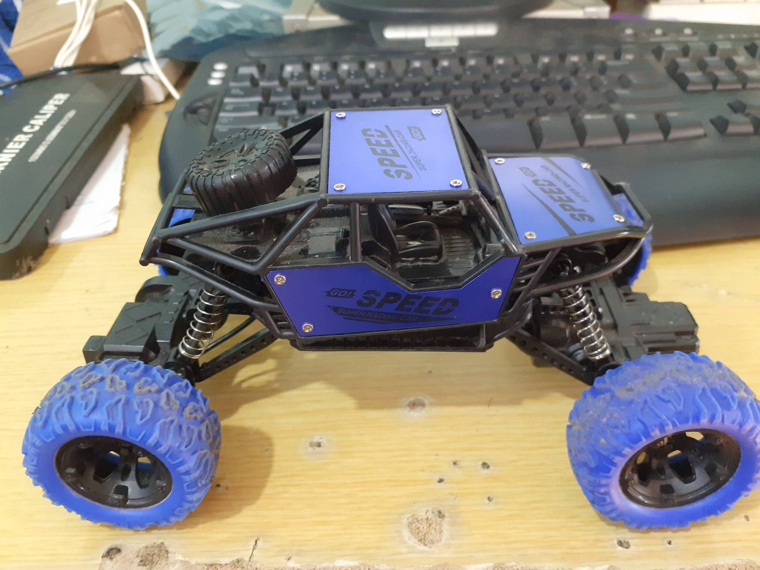
In the picture above, we can clearly see that there is not a lot going on inside this toy car. An On-Off switch is connected to the battery compartment, and two wires go to the drive- and steering motor.
Interfacing this car to a microcontroller is thus going to require two separate H-Bridge circuits. One for the drive motor, and the second for the steering.

I have designed the circuit above to control both motors of the toy car, the control signals are simplified to 2 per H-Bridge, and a common PWM signal to control speed.
Manufacturing the PCB
The PCB for this project is currently on its way from China, after having been manufactured at PCBWay.
Please consider supporting them if you would like your own copy of this PCB, or if you have any PCB of your own that you need to be manufactured.

If you would like to have PCBWAY manufacture one of your own, designs, or even this particular PCB, you need to do the following…
1) Click on this link
2) Create an account if you have not already got one of your own.
If you use the link above, you will also instantly receive a $5USD coupon, which you can use on your first or any other order later. (Disclaimer: I will earn a small referral fee from PCBWay. This referral fee will not affect the cost of your order, nor will you pay any part thereof.)
3) Once you have gone to their website, and created an account, or login with your existing account,

4) Click on PCB Instant Quote

5) If you do not have any very special requirements for your PCB, click on Quick-order PCB

6) Click on Add Gerber File, and select your Gerber file(s) from your computer. Most of your PCB details will now be automatically selected, leaving you to only select the solder mask and silk-screen colour, as well as to remove the order number or not. You can of course fine-tune everything exactly as you want as well.


7) You can also select whether you want an SMD stencil, or have the board assembled after manufacturing. Please note that the assembly service, as well as the cost of your components, ARE NOT included in the initial quoted price. ( The quote will update depending on what options you select ).

8) When you are happy with the options that you have selected, you can click on the Save to Cart Button. From here on, you can go to the top of the screen, click on Cart, make any payment(s) or use any coupons that you have in your account.
Then just sit back and wait for your new PCB to be delivered to your door via the shipping company that you have selected during checkout.