
In this, part 3 of the “Giving new Life to an Old Toy Car” series, we will be adding some flashing lights to the toy car project. This will ultimately serve two purposes, with the most obvious being to give some life and excitement to the project ( as the final user will be a young boy of 7, the visual aspect is important). The second purpose is more obscured, and mostly only useable to programmers and coders, or those that will debug the project… The flashing lights will function as status indicators, at startup, as well as during the normal operation of the toy. Obviously, the diagnostic nature should be well obscured so as to not distract from the visual aspects.
The flasher unit is made up of an extremely simple circuit, with only a PCF8574 IO expander, bypass capacitors, some LED lights, and current limiting resistors.


Schematic

The schematic is straightforward, with no surprises, consisting only of a few components, like the PCB8574, bypass capacitors, current limiting resistors, and of course the LEDs. It is also important to remember that I plan to use this entire robot car to teach a young boy to program microprocessors. I believe that visual is best, thus, all the lights 🙂
Coding
As this is still a project in quite a lot of development stages, I will not publish my exact code at this moment. You can however look forward to the future conclusion post, which will contain all my code at that stage.
For now, however, we need to keep in mind that the PCF8574 is an I2C port expander, with an 8-bit IO port.
It is thus possible to do something simple like the below:
#include <Wire.h>

void setup() {
 wire.begin();
 wire.beginTransmission(0x20);
 wire.write(0b11111111); // All LEDS off
 // our circuit is sinking current into the io expander
 wire.endTransmission();
delay(1000); // delay for illustration purposes, production code will use
// non blocking code
wire.beginTransmission(0x20);
 wire.write(0b10100101); // All blue LED on
 // our circuit is sinking current into the io expander
 wire.endTransmission();
delay(1000);
}

void loop() {
}
Obviously, this is just a very quick example and is meant to just test functionality. Your own application will ultimately determine the exact code that you would need.
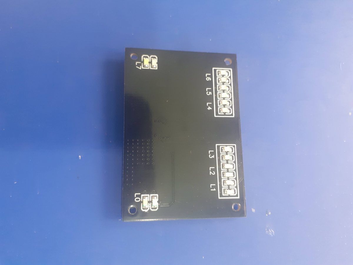
Manufacturing the PCB
The PCB for this project is currently on its way from China, after having been manufactured at PCBWay.
Please consider supporting them if you would like your own copy of this PCB, or if you have any PCB of your own that you need to be manufactured.

If you would like to have PCBWAY manufacture one of your own, designs, or even this particular PCB, you need to do the following…
1) Click on this link
2) Create an account if you have not already got one of your own.
If you use the link above, you will also instantly receive a $5USD coupon, which you can use on your first or any other order later. (Disclaimer: I will earn a small referral fee from PCBWay. This referral fee will not affect the cost of your order, nor will you pay any part thereof.)
3) Once you have gone to their website, and created an account, or login with your existing account,

4) Click on PCB Instant Quote

5) If you do not have any very special requirements for your PCB, click on Quick-order PCB

6) Click on Add Gerber File, and select your Gerber file(s) from your computer. Most of your PCB details will now be automatically selected, leaving you to only select the solder mask and silk-screen colour, as well as to remove the order number or not. You can of course fine-tune everything exactly as you want as well.


7) You can also select whether you want an SMD stencil, or have the board assembled after manufacturing. Please note that the assembly service, as well as the cost of your components, ARE NOT included in the initial quoted price. ( The quote will update depending on what options you select ).

8) When you are happy with the options that you have selected, you can click on the Save to Cart Button. From here on, you can go to the top of the screen, click on Cart, make any payment(s) or use any coupons that you have in your account.
Then just sit back and wait for your new PCB to be delivered to your door via the shipping company that you have selected during checkout.![]()