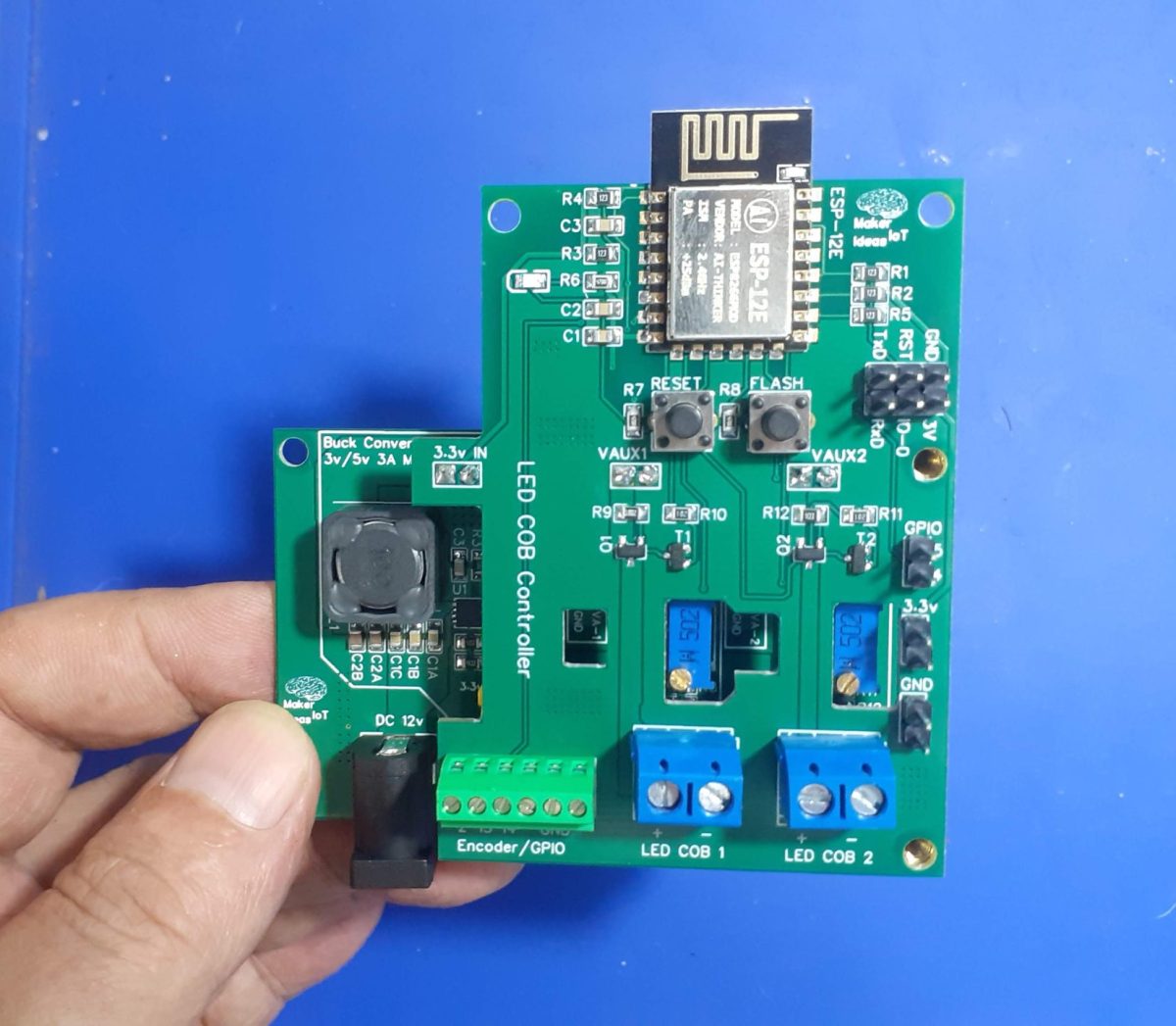
COB LED lights, or Chip-on-Board LED lights, are a type of LED light that has all of the LED chips mounted on a single substrate. This makes them more efficient than traditional LED lights, which have individual LED chips mounted on a circuit board. COB LED lights also produce a more uniform light output, and they can be used in a wider variety of applications.
Here are some of the benefits of using LED COB lights:
- are very efficient, and they can produce up to 100 lumens per watt. This means that they use less energy than traditional light bulbs, and they can save you money on your energy bills.
- produce a more uniform light output than traditional LED lights. This means that they do not create hot spots or shadows, and they provide a more comfortable light to work under.
- are very durable, and they can last for many years. They are not as susceptible to damage from heat or vibration as traditional light bulbs, and they can withstand harsh conditions.
- can be used in a wide variety of applications, including indoor and outdoor lighting, commercial and residential lighting, and automotive lighting.
They can however be quite a pain to power in a traditional 110v/220v AC wired house or workshop, as some of them actually required DC current to work.
I have decided to use a pair of them to provide additional, dimmable light at my electronics workbench, a place where extra light is sometimes a very necessary commodity. The ability to dim the lights will definitely aid in many scenarios as well.
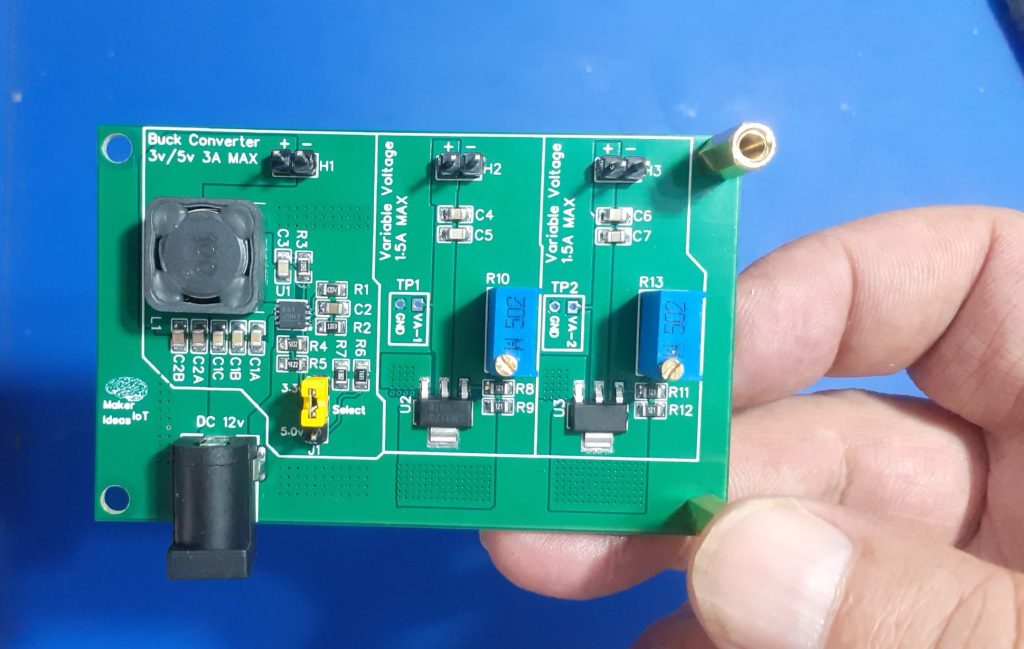
The project consists of two main parts, the first being the Variable Voltage Power Module, which I published a few days ago. The particular COB lights that I will be using, were scavenged from a battery-operated emergency light panel, which had some problems which were not economical to repair. The light modules themselves, however, looked good and were perfectly working as well.
The only issue was that they were 6v DC. So using straight 12v there was out of the question. 6V being an odd voltage in my lab, I designed the module above specifically to provide that.
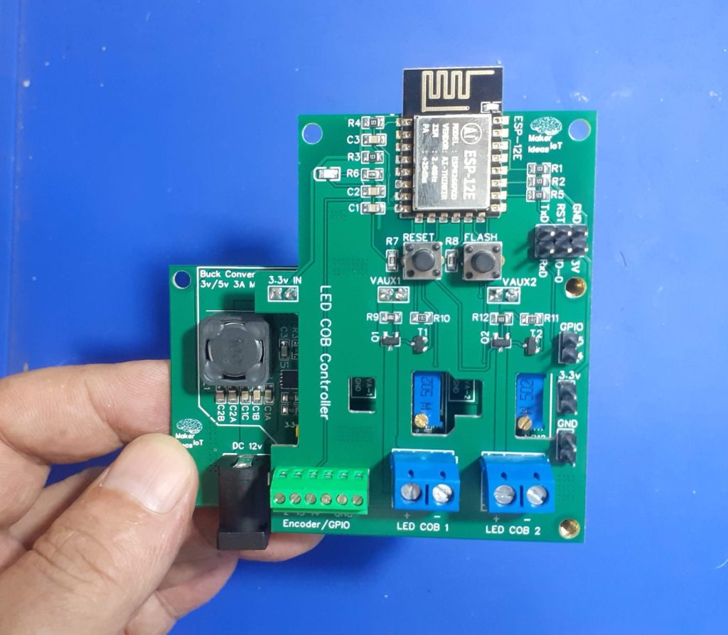
The second part of the project consists of a simple Custom ESP-12E PCB. Why ESP12-E? Well, I have a lot of them lying in stock, and since I won’t need any advanced features, commonly found on the bigger ESP32s, I decided to design around something that I have in stock, rather than overcomplicate the design with a bigger more advanced chip. The project features a rotary encoder, to adjust light intensity, as well as push buttons to toggle the lights on or off…
All of this is of course controlled with ESPHome. This choice gives me the option of manual or fully automatic control from HomeAssistant. It also saves me a lot of coding, as everything usually just works.
What is on the PCB?
We shall focus mainly on LED COB Controller PCB.
In order to understand everything, please refer to the picture below:
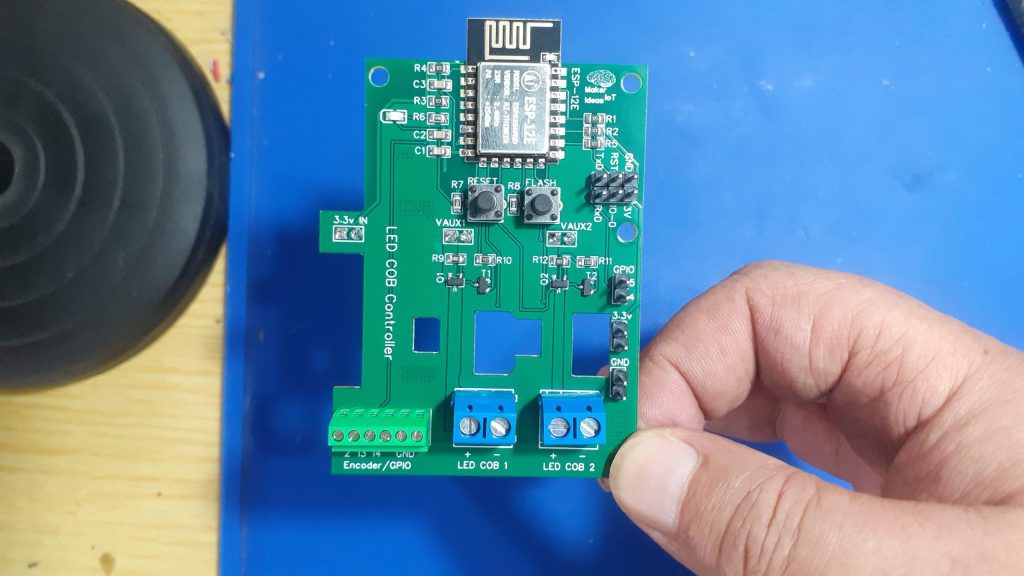

The board consists of a few sections, which can be divided as follows:
ESP-12E (8266) supporting circuitry
The top area is mainly the supporting circuitry for the ESP-12E, which includes a 6-pin header to flash firmware, the classic ESP32/8266 Auto Flash/Reset circuit, and manual Flash and Reset switches. Note that the board DOES NOT contain any USB-to-Serial circuitry. I usually use those only once or twice, and update firmware OTA after that. Using an external USB-to-Serial adapter is thus sufficient for my purposes.
Power and LED Control circuitry
Power enters the board in the center, using header pins mounted on the bottom of the PCB. From left to right, these are 3.3v and then two variable voltage inputs. These all originate from the Variable voltage Power Module, mounted below the main PCB. The LED Control circuitry consists of two P-Channel Mosfets, the configuration of which was previously tested in another project, the “P-MOS MOSFET Driver Board“, also published a few weeks ago. The SI2301 P-Channel Logic Level MOSFET, used here is capable of switching up to 2.3A at 20v, and thus more than capable of handling the 300mA that the LED COB modules require.
Four cutouts are provided to access test points on the power module below, as well as the potentiometers used to set the voltage that will ultimately be sent to the LED COB Modules.
Wide copper traces connect the Mosfet’s to Screw Terminals for the LED Modules.
The Final part of the PCB is dedicated to control interfaces. A single 6-way screw terminal is provided at the bottom left corner, this is used to connect a rotary encoder, or give direct access to additional GPIO pins. On the Right hand side of the PCB, a series of header pins give access to additional 3.3v and ground connections, in addition to GPIO 4 and 5, which is usually used for I2C…


The Schematic
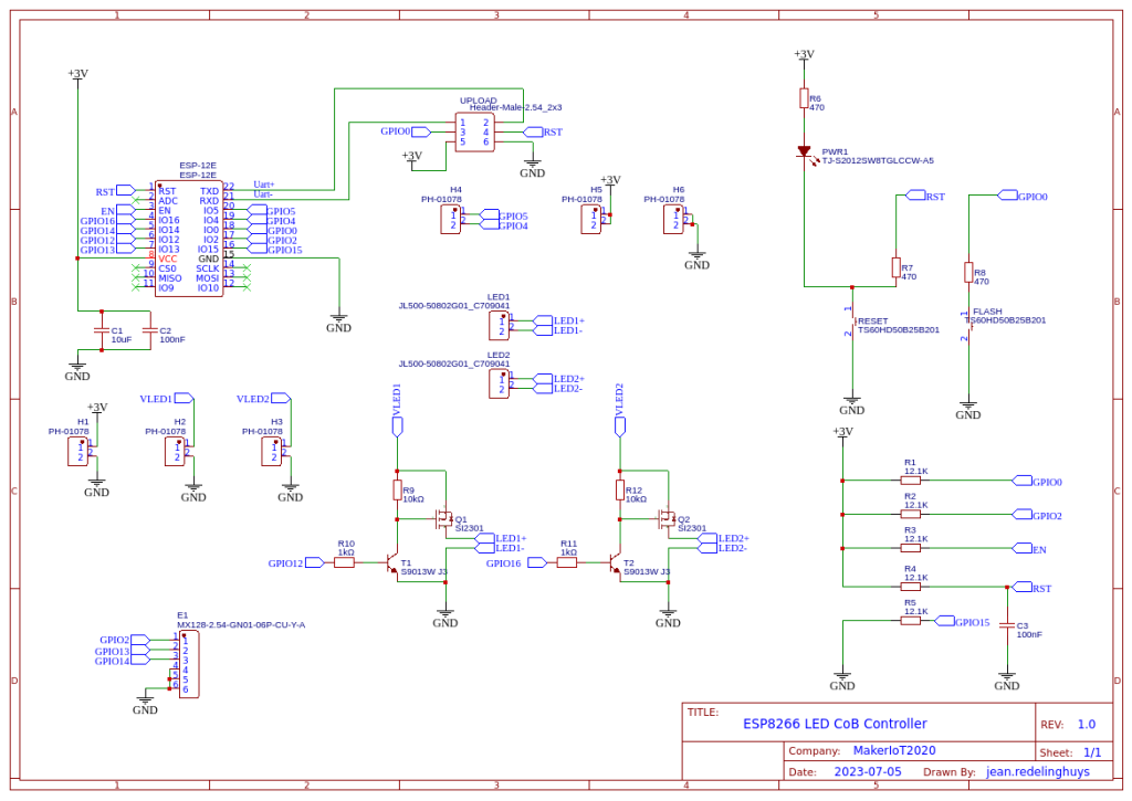

Configuration and Software
As mentioned above, this device was designed to be used with ESPHome. The configuration is thus a single YAML file and can be greatly customised to suit your exact needs…
With that in mind, I present here a VERY basic YAML file, that will toggle the LED lights on or off on pressing the encoder switch, as well as adjust the brightness by turning the encoder.
esphome:
  name: led-cob-controller
  friendly_name: LED_COB-Controller

esp8266:
  board: nodemcuv2
  restore_from_flash: True

# Enable logging
logger:

# Enable Home Assistant API
api:
  encryption:
    key: "<esphome generated>"

ota:
  password: "<esphome generated>"

wifi:
  ssid: !secret wifi_ssid
  password: !secret wifi_password

  # Enable fallback hotspot (captive portal) in case wifi connection fails
  ap:
    ssid: "Led-Cob-Controller"
    password: "<your recovery password here>"

captive_portal:

# I suggest you only copy paste from here on downwards.
# Setup the default device in ESPHome, and when it is available,
# come back and add the commands below here


text_sensor:
  - platform: wifi_info
    ip_address:
      name: IP Address
    ssid:
      name: SSID
    bssid:
      name: BSSID
    mac_address:
      name: Wifi MAC
    scan_results:
      name: WiFi Scan Results


sensor:
  - platform: adc
    pin: VCC
    name: "ESP8266 Chip Voltage"
    id: mcu_voltage
    unit_of_measurement: "V"
    device_class: "voltage"
    accuracy_decimals: 2
    update_interval: 60s
    entity_category: "diagnostic"

  - platform: wifi_signal
    name: "WiFi Signal Sensor"
    id: wifi_strength
    device_class: "signal_strength"
    unit_of_measurement: "dBm"
    update_interval: 240s
    entity_category: "diagnostic"

  - platform: copy # Reports the WiFi signal strength in %
    source_id: wifi_strength
    name: "WiFi Signal Strength"
    filters:
      - lambda: return min(max(2 * (x + 100.0), 0.0), 100.0);
    unit_of_measurement: "%"
    entity_category: "diagnostic"

  - platform: copy
    source_id: rcbright
    name: "LED Light Brightness"
    unit_of_measurement: "%"
    filters:
      - lambda: return (x * 100);

  - platform: rotary_encoder
    name: "Brightness Control"
    id: rcbright
    min_value: 0.00
    max_value: 100.00
    publish_initial_value: True
    restore_mode: RESTORE_DEFAULT_ZERO

    pin_a:
      number: GPIO13
      inverted: True
      mode:
        input: True
        pullup: True

    pin_b:
      number: GPIO2
      inverted: True
      mode:
        input: True
        pullup: True

    resolution: 1
    accuracy_decimals: 2
    filters:
    - lambda: return x / 100 ;
    on_clockwise:
    - light.control:
        id: led_light1
        brightness: !lambda |-
          // output value must be in range 0 - 1.0
          return id(rcbright).state ; // /100.0;
    - light.control:
        id: led_light2
        brightness: !lambda |-
          // output value must be in range 0 - 1.0
          return id(rcbright).state ; // /100.0;
    on_anticlockwise:
    - light.control:
        id: led_light1
        brightness: !lambda |-
          return id(rcbright).state ;
    - light.control:
        id: led_light2
        brightness: !lambda |-
          // output value must be in range 0 - 1.0
          return id(rcbright).state ; // /100.0;

binary_sensor:
  - platform: gpio
    pin: GPIO14
    id: light_switch
    name: "Light Switch"
    device_class: light
    on_click:
      then:
        - light.toggle: led_light1
        - light.toggle: led_light2


light:
  - platform: monochromatic
    name: "LED1_LIGHT_TEST"
    id: led_light1
    output: output_component1
  - platform: monochromatic
    name: "LED2_LIGHT_TEST"
    id: led_light2
    output: output_component2

# Example output entry
output:
  - platform: esp8266_pwm
    id: output_component1
    pin: GPIO12
  - platform: esp8266_pwm
    id: output_component2
    pin: GPIO16
Manufacturing the PCB
I choose PCBWay for my PCB manufacturing. Why? What makes them different from the rest?
PCBWay‘s business goal is to be the most professional PCB manufacturer for prototyping and low-volume production work in the world. With more than a decade in the business, they are committed to meeting the needs of their customers from different industries in terms of quality, delivery, cost-effectiveness and any other demanding requests. As one of the most experienced PCB manufacturers and SMT Assemblers in China, they pride themselves to be our (the Makers) best business partners, as well as good friends in every aspect of our PCB manufacturing needs. They strive to make our R&D work easy and hassle-free.
How do they do that?
PCBWay is NOT a broker. That means that they do all manufacturing and assembly themselves, cutting out all the middlemen, and saving us money.
PCBWay’s online quoting system gives a very detailed and accurate picture of all costs upfront, including components and assembly costs. This saves a lot of time and hassle.
PCBWay gives you one-on-one customer support, that answers you in 5 minutes ( from the Website chat ), or by email within a few hours ( from your personal account manager). Issues are really resolved very quickly, not that there are many anyway, but, as we are all human, it is nice to know that when a gremlin rears its head, you have someone to talk to that will do his/her best to resolve your issue as soon as possible.
Find out more here


Assembly and Testing
This device does not need a stencil for assembly, but using one will definitely speed up things. I chose to do this build all by hand, from applying solder-paste, up to placing components.
Soldering was done on a hotplate, as usual, to reflow everything at the same time. TH components were then placed and hand-soldered.
Uploading the initial firmware, after adding the device to ESPHome was done with an external USB-to-UART converter. All further firmware changes were made via OTA.
The board performs well, with only slight heating of the LM317G variable voltage regulators on the power module when both LED COB modules are at 100% brightness. The current draw is within limits and seems to peak at about 600mA per COB…
Conclusion
This project took quite a while to move from idea to practical reality, mainly due to being busy with other more important stuff. In the end, I am happy that I sat down and did it, because it definitely will become a valuable tool in my work area.

