

SX127x LoRa/FSK/OOK Prototype Radio Board
I recently had a requirement to do some automation/telemetry on the farm. Things went missing, unauthorised persons were trespassing on the property, helping themselves to eggs, chickens, ducks and produce. Something had to be done, and as there is nobody sleeping there at night, it had to be possible to get remote status updates in real-time.
The farm is also completely off-grid, with solar-powered inverters taking care of all the water and electricity needs. Power usage monitoring could thus be a great help as well…
The idea is as follows:
Have a central control station, with various remote devices to do intrusion detection, control lights and water pumps, as well as monitor the battery levels of the inverter and solar-panel system. As the area is quite large, having to pull in electrical cabling will not be feasible, nor could the inverter handle all of that.
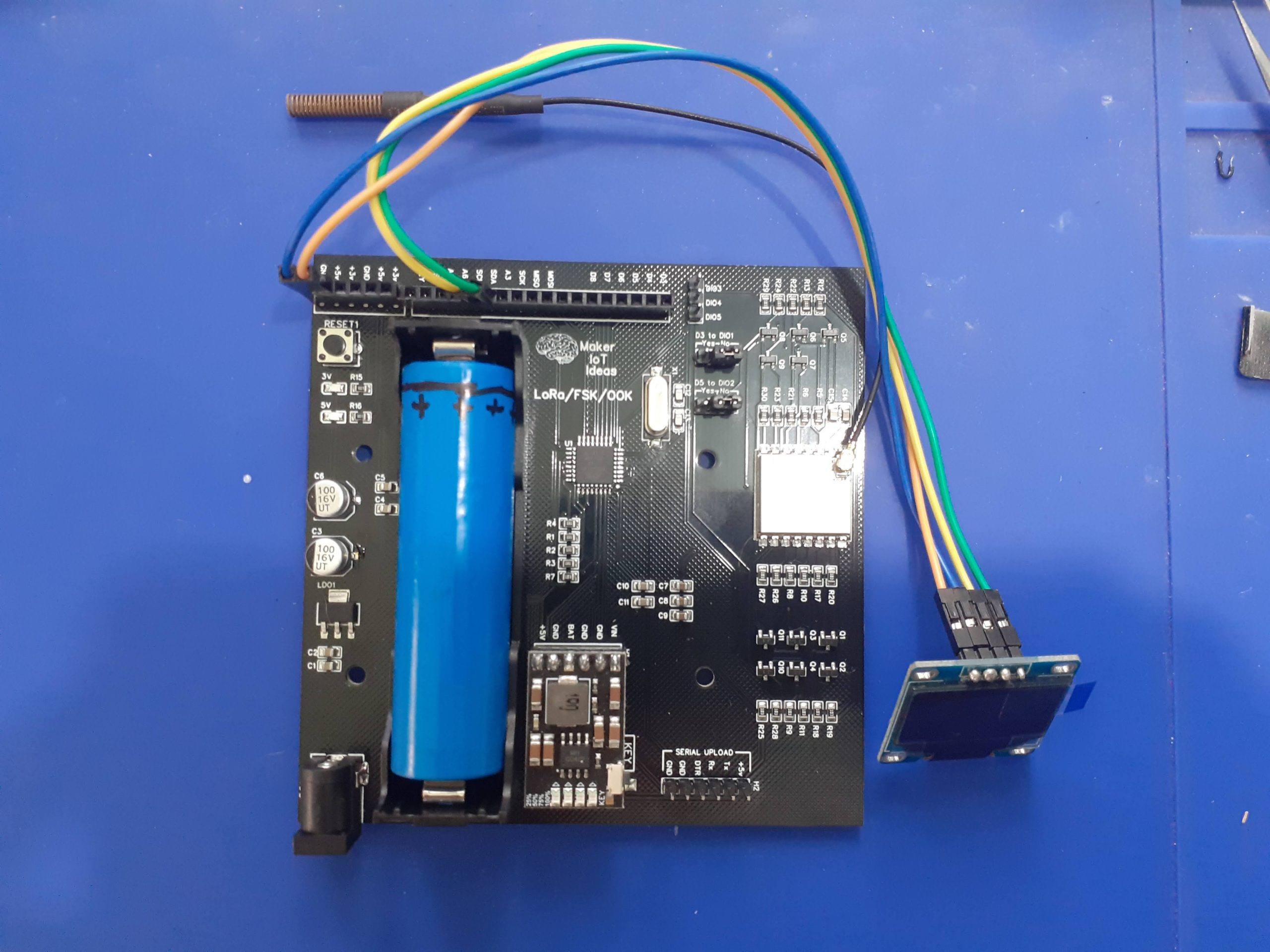
I decided to use the RA-02 LoRa/FSK/OOK module, on a custom PCB, but with various different PCB modifications, to take care of each stage of the project. The PCB that I will present today will be mainly used as the control unit, but it could also be a remote station, depending on what options are needed.
The ATMEGA328P-AU MCU is used as the main processor on each board, with the MH-CD42 Boost Converter/LiPo battery charger module taking care of power supply requirements. This module can source up to 2A at 5.0v, More than adequate for my needs. The ATMEGA328P will be put into sleep mode, to wake on interrupt to respond to events as needed ( To help save power ). Power usage of the circuit is around 50mA in standby ( NOT SLEEP MODE ), and with a peak of 100mA on a LoRa Transmit or Receive event.
The RA-02 Module did however present some challenges, as it is a 3.3v device, with non-5v capable IO lines. This made it necessary to include a 3.3v LDO regulator, as well as logic level converting circuitry onto the PCB. To allow for the most flexibility, all DIOs on the RA-02 was also broken out via level converters, in addition to the required SPI pins ( MOSI, MISO, CE and SCK ). This amount to a total of 11 level converters onboard.
I chose the MH-CD42 Power module for the reason that it can supply current at the same time as charging the LiPo battery (in my case, I used a 18650 cell). This will help greatly, as 220v inverter power is available during the day to charge the batteries.
The PCB can be ordered at PCBWay by clicking here

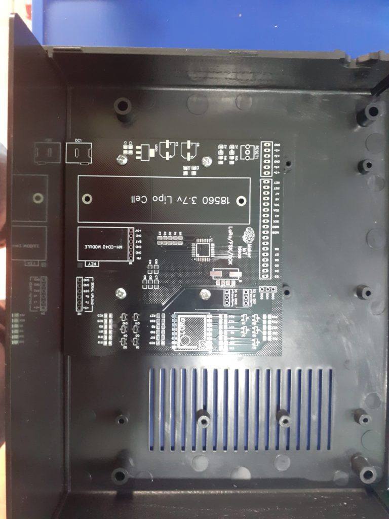
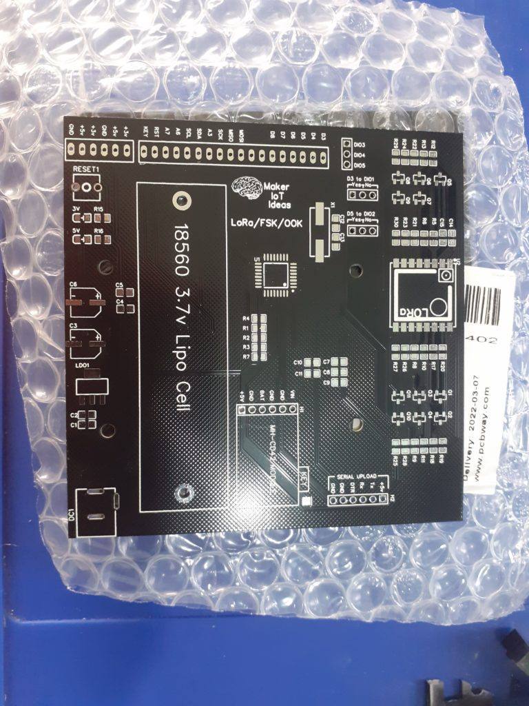
Another challenge was definitely the enclosure. I found some really nice enclosures online, but the mounting holes were located in a very particular pattern, making it necessary to do some very careful measuring to get the PCB to fit exactly. The enclosure also has space to accept the other PCB modules, like the USER Control panel, and other sensor devices as needed. PCBWay did a great job at manufacturing the PCB so as to fit exactly. I must admit that I had quite a few tense moments between sending the PCB off to manufacturing and receiving it, as to whether my measurements were actually accurate, and if the PCB would fit as I imagined…
As you can see in the picture above, it turned out perfectly.
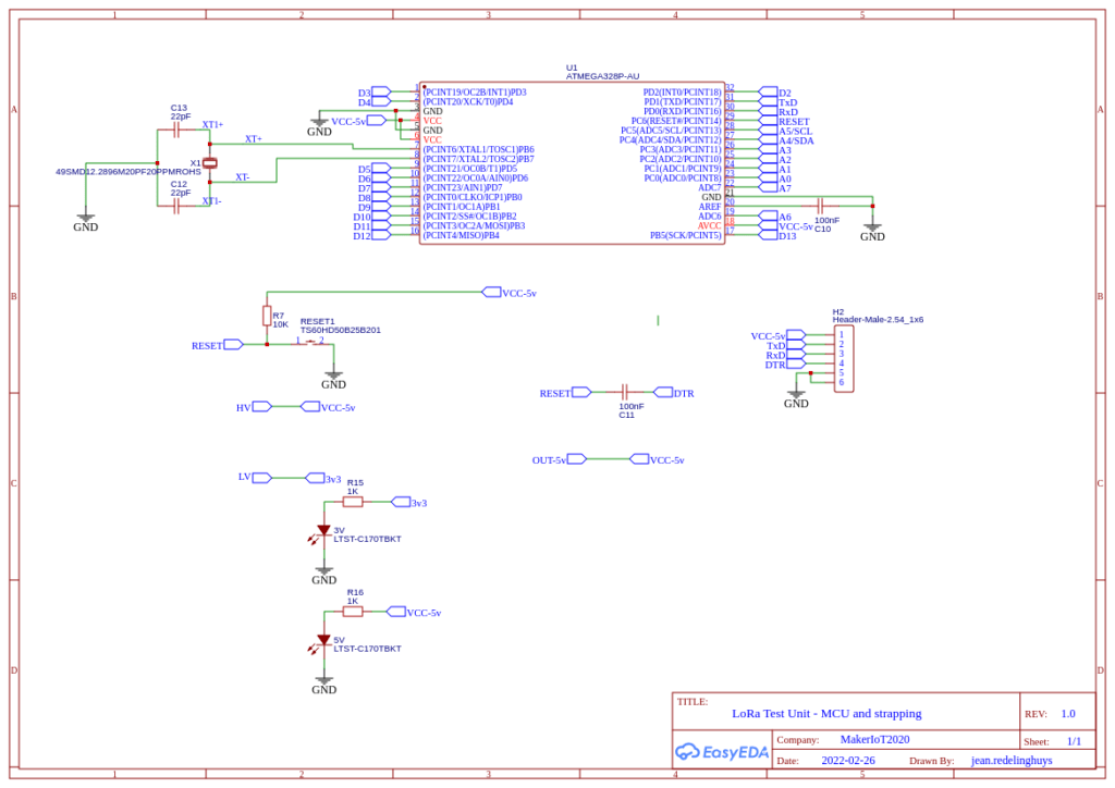
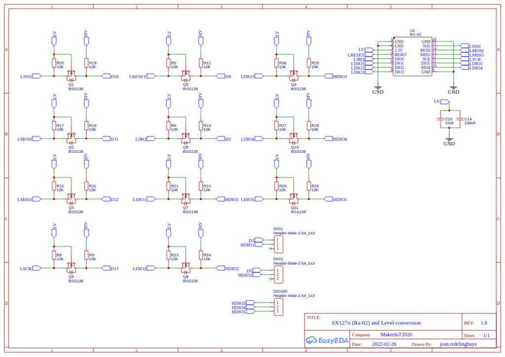
The Circuit diagram is basically a standard Arduino Nano ( I needed access to all of the ADC pins ),
Connections to the RA-02 module is as follows:
| RA-02 | ATMEGA328P |
| MOSI | D11 |
| MISO | D12 |
| SCK | D13 |
| CE | D10 |
| RESET | D9 |
| DIO0 | D2 ( We need a hardware interrupt pin here ) |
| DIO1 | D3 ( Hardware Interrupt, enabled through jumper) |
| DIO2 | D5 ( Enabled through a jumper) |
| DIO3 to DIO 5 | Not connected, available on a breakout header |
On the ATMEGA328, the following pins are broken out into headers:
| D3 | can be connected to RA-02 with a jumper |
| D4 | |
| D5 | can be connected to RA-02 with a jumper |
| D6 | |
| D7 | |
| D8 | |
| D13 ( SCK ) | Broken out as a 5v logic pin |
| D12 ( MISO ) | 5v logic pin |
| D11 ( MOSI ) | 5v logic pin |
| A3,A6,A7 | ADC Pins ( A0, A1, A2 is used internally to monitor VIN, VCC5v and VCC3v ) A0 = Vcc3v A1 = Vcc5v A2 = VIN |
| SCL | I2C SCL pin OR A5 (I2C pins are at 5v logic levels ) |
| SDA | I2C SDA pin OR A4 (I2C pins are at 5v logic levels ) |
| RESET | |
| DTR | ( connected through a 100nf Cap to Reset, used for serial uploading firmware ) |
| D0 ( RxD ) | UART Rx Pin ( 5v logic ) |
| D1 ( TxD ) | UART Tx Pin ( 5v logic ) |
The ATMEGA328P is clocked at 16Mhz through an external crystal.
3v, 5v and GND pins were broken out at two opposite corners of the PCB to allow easy connection of additional devices/ sensors as needed.
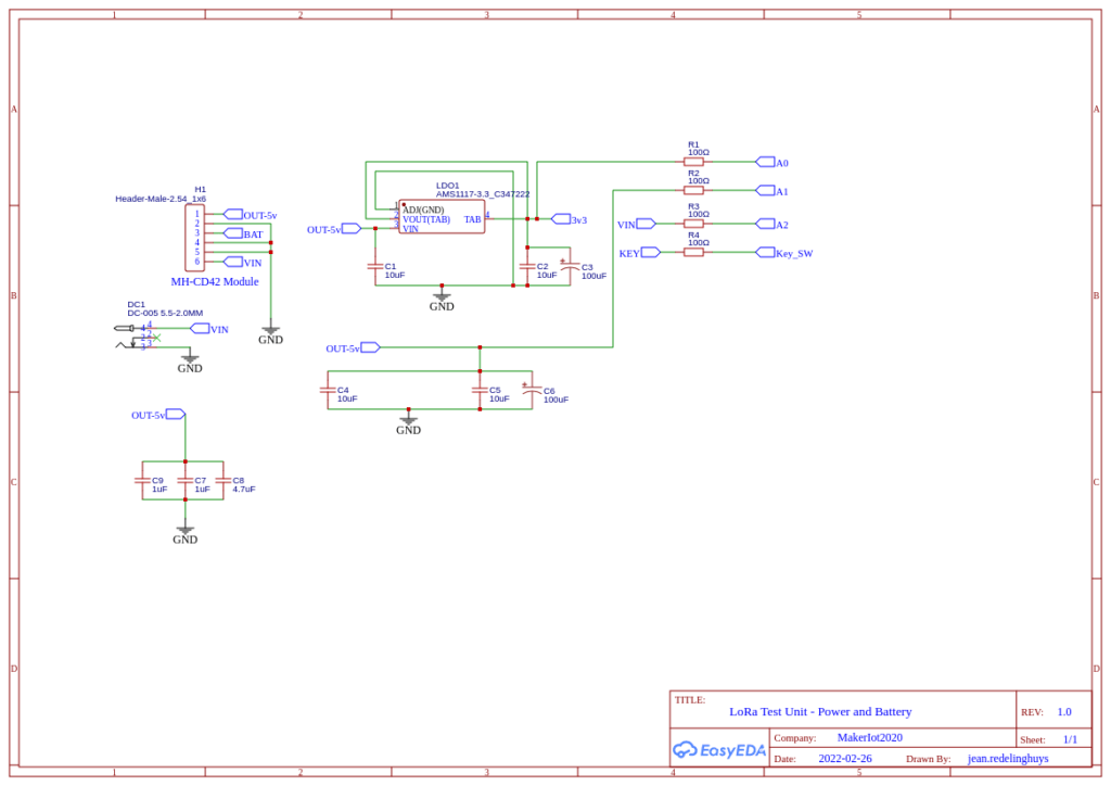
Powering the PCB
The PCB can be ordered at PCBWay by clicking here
The MH-CD42 module has the capability to power a load while charging the LiPo battery. This makes it possible to do a few interesting things while supplying power to this particular PCB.
The board can be powered directly from a 5v header pin ( NOT from the DC1 input ). In this mode, a LiPo battery is not required.
5v will be directly supplied to the processor, as well as the 3.3v LDO regulator, allowing the RA-02 module to function as well.
PLEASE NOTE: THERE ARE NO 5v REGULATION – MAKE SURE YOU SUPPLY REGULATED 5v
Installing the MH-CD42 module will add the option of charging a 3.3v 18650 Lipo battery, as well as powering the board at the same time. You need to supply power through the DC plug to make use of this function. This mode is also a miniature uninterruptible power supply, with the 3.3v LiPo battery immediately taking over should the main DC input fail.
NOTE: The MH-CD42 can only accept up to 5.5v MAXIMUM as input!
Software:
The PCB can be used with LoRa libraries from Sandeep Mistry OR JGromes/RadioLib ( If you want to do FSK/OOK or other advanced stuff like LoRa of FHSS)
Sandeep Mistry LoRa Module
JGROMES/RADIOLIB
Both libraries have extensive examples showing how to use them. As our use case will definitely differ, I will not have any example here at this stage. I will add one later after the entire project is completed, with all the relevant modules.
The PCB can be ordered at PCBWay by clicking here
This PCB was manufactured at PCBWAY. The Gerber files and BOM, as well as all the schematics, will soon be available as a shared project on their website. If you would like to have PCBWAY manufacture one of your own, designs, or even this particular PCB, you need to do the following…
1) Click on this link
2) Create an account if you have not already got one of your own.
If you use the link above, you will also instantly receive a $5USD coupon, which you can use on your first or any other order later. (Disclaimer: I will earn a small referral fee from PCBWay. This referral fee will not affect the cost of your order, nor will you pay any part thereof.)
3) Once you have gone to their website, and created an account, or login with your existing account,

4) Click on PCB Instant Quote

5) If you do not have any very special requirements for your PCB, click on Quick-order PCB
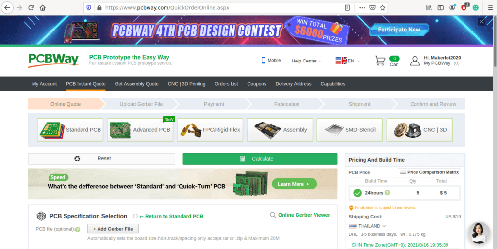
6) Click on Add Gerber File, and select your Gerber file(s) from your computer. Most of your PCB details will now be automatically selected, leaving you to only select the solder mask and silk-screen colour, as well as to remove the order number or not. You can of course fine-tune everything exactly as you want as well.


7) You can also select whether you want an SMD stencil, or have the board assembled after manufacturing. Please note that the assembly service, as well as the cost of your components, ARE NOT included in the initial quoted price. ( The quote will update depending on what options you select ).
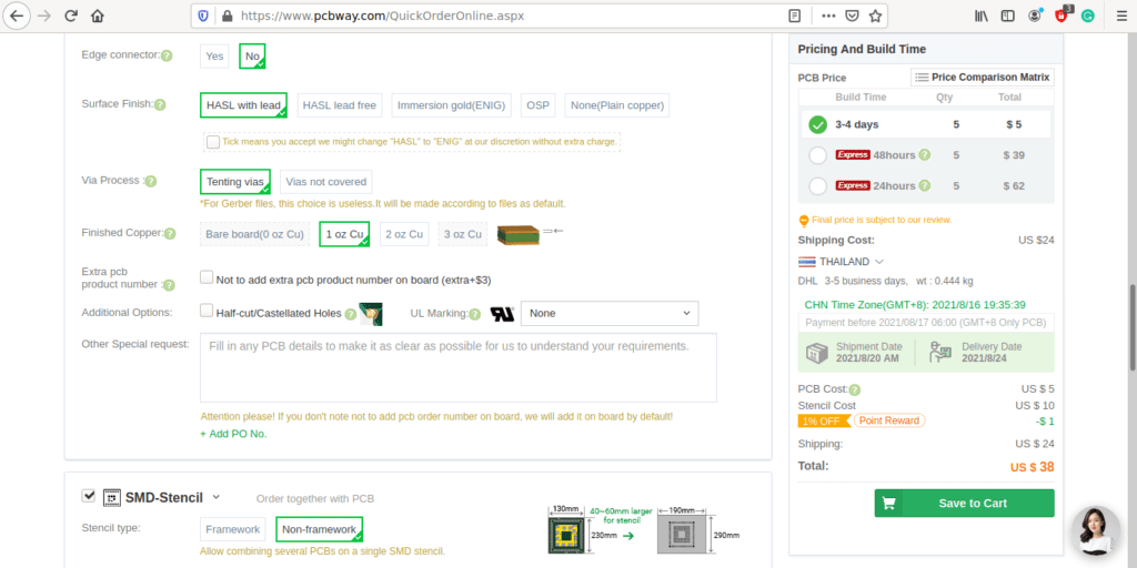

8) When you are happy with the options that you have selected, you can click on the Save to Cart Button. From here on, you can go to the top of the screen, click on Cart, make any payment(s) or use any coupons that you have in your account.
Then just sit back and wait for your new PCB to be delivered to your door via the shipping company that you have selected during checkout.