I2C IO Card for ESP-12E I2C Base Card

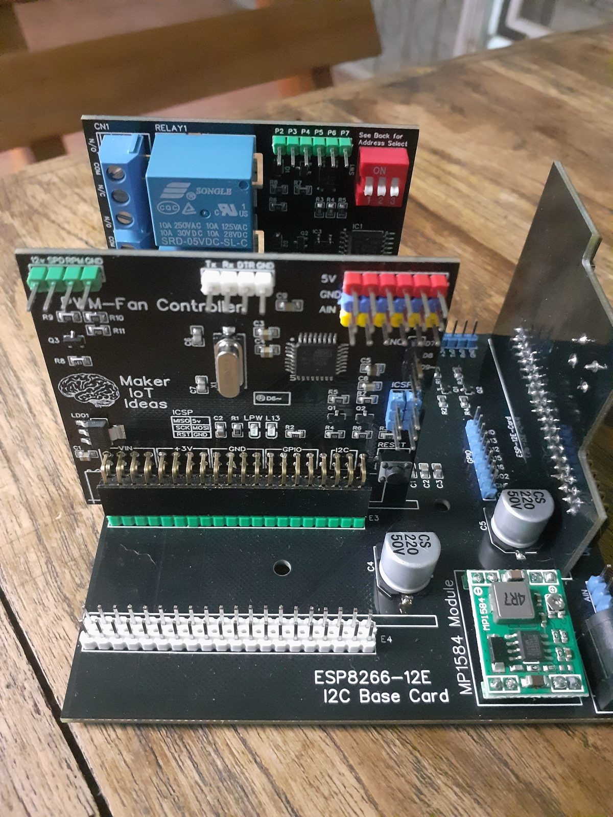
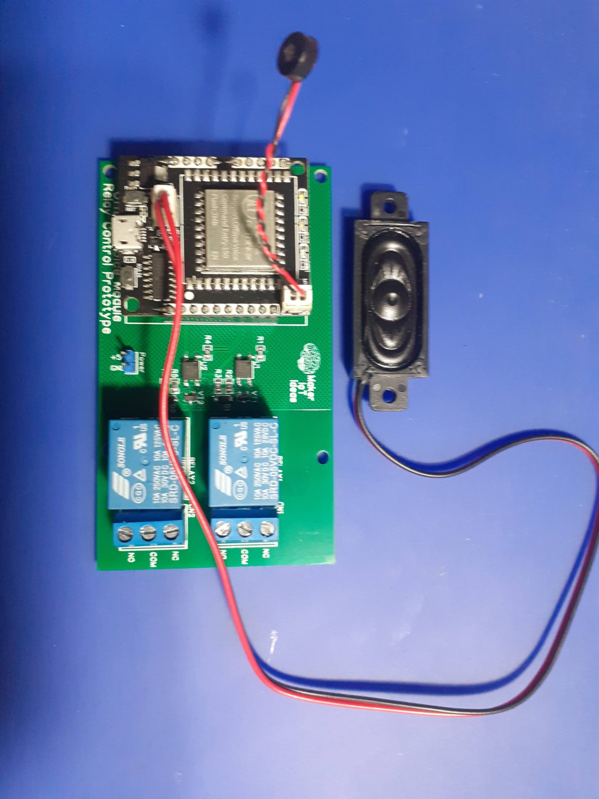
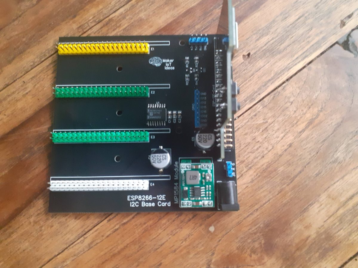
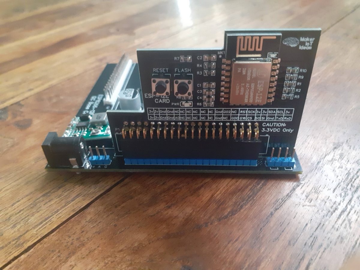
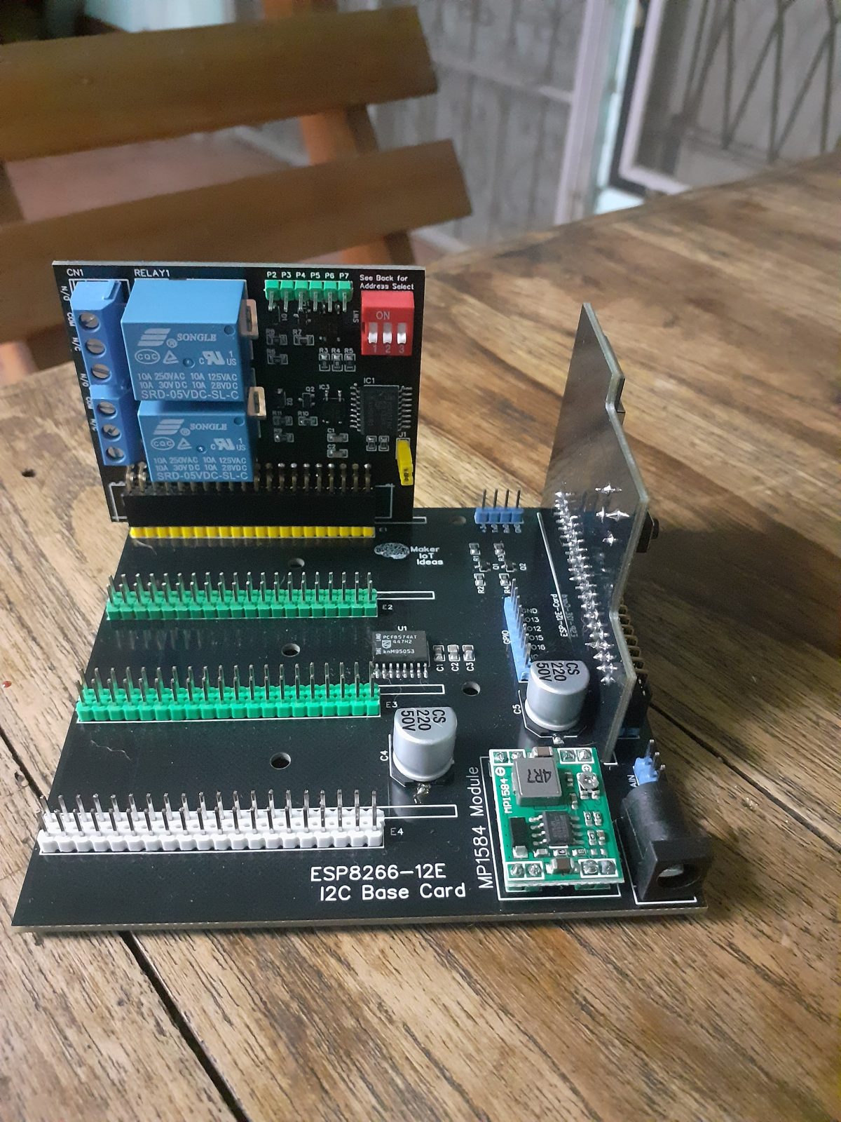
The I2C IO Card for ESP-12E I2C Base Card is another expander card for the ESP-12E I2C Base Card Project. This PCB is an address-selectable I2C module with two relays and six (6) GPIO pins, all driven from a single PCF8574 running at 3v. The relays are optically isolated, and generous mains isolation cutouts were provided to reduce the possibility of mains voltage tracking. A jumper to enable/disable the i2c pullup-resistors is also provided on the PCB.

The relays are powered from a single LDO regulator, accepting 12v DC from the 2x20pin female header on the bottom of the card. 3.3v and ground should also be applied to the card at the 2x20pin header.

It is worth mentioning that this circuit does not contain level converting circuitry and that the i2c bus thus runs at 3.3v to be compatible with ESP chips.

It is possible to use the card with other processors if the appropriate level converters are used on the i2c bus.

The Schematic

Manufacturing the PCB


Over the past eight years, PCBWay has continuously upgraded their MANUFACTURING plants and equipment to meet higher quality requirements, and now THEY also provide OEM services to build your products from ideas to mass production and access to the market.


The PCB for this project has been manufactured at PCBWay.
Please consider supporting them if you would like your own copy of this PCB, or if you have any PCB of your own that you need to have manufactured.

PCBWay

If you would like to have PCBWAY manufacture one of your own, designs, or even this particular PCB, you need to do the following…
1) Click on this link
2) Create an account if you have not already got one of your own.
If you use the link above, you will also instantly receive a $5 USD coupon, which you can use on your first or any other order later. (Disclaimer: I will earn a small referral fee from PCBWay. This referral fee will not affect the cost of your order, nor will you pay any part thereof.)
3) Once you have gone to their website, and created an account, or login with your existing account,

4) Click on PCB Instant Quote

5) If you do not have any very special requirements for your PCB, click on Quick-order PCB

6) Click on Add Gerber File, and select your Gerber file(s) from your computer. Most of your PCB details will now be automatically selected, leaving you to only select the solder mask and silk-screen colour, as well as to remove the order number or not. You can of course fine-tune everything exactly as you want as well.

7) You can also select whether you want an SMD stencil, or have the board assembled after manufacturing. Please note that the assembly service, as well as the cost of your components, ARE NOT included in the initial quoted price. ( The quote will update depending on what options you select ).

8) When you are happy with the options that you have selected, you can click on the Save to Cart Button. From here on, you can go to the top of the screen, click on Cart, make any payment(s) or use any coupons that you have in your account.

Then just sit back and wait for your new PCB to be delivered to your door via the shipping company that you have selected during checkout.

ATMega 328P Based PWM controller Card

As part of my recent ESP-12E I2C Base Board project, I designed an ATMega 328P Based PWM controller card, that can be used as an add-on card with the existing project, or standalone as a custom Arduino Nano compatible development board.

What is on the PCB?

The PWM controller card contains standard Arduino Nano circuitry running at 16MHz, without the USB to Serial converter, as well as a 3v to 5v level converter on the I2C port ( A4 and A5 ), as well as another 12v to 5v level converter, with a build in resistor-divider circuit, used to drive a 12v blower with 3.3v PWM control circuitry.

All analog inputs are broken out to make attaching additional sensors easier.

All the other unused GPIO pins are also broken out, either directly to headers on the PCB (D6~,D7,D8,D9~), D11,D12,D12 (ISCP Header) and D3 ( Marked RPM on the Fan Header)

Most of these pins are also additionally broken out onto the 2x20p female header at the bottom of the card ( See schematic for more details)

The board is designed to be powered from 12v DC (via the VIN pins on the 2x20p header) which is internally regulated down to 5v via an LDO voltage regulator.


External 3.3v should also be supplied to the 2x20Pin header to enable the I2C level converters on the same header. I2C is not directly broken out onto the PCB in this version of the PCB.

A reset button, and power led, as well as the standard led on D13 is also provided.

Manufacturing the PCB


Over the past eight years, PCBWay has continuously upgraded their MANUFACTURING plants and equipment to meet higher quality requirements, and now THEY also provide OEM services to build your products from ideas to mass production and access to the market.


The PCB for this project has been manufactured at PCBWay.
Please consider supporting them if you would like your own copy of this PCB, or if you have any PCB of your own that you need to have manufactured.

PCBWay

If you would like to have PCBWAY manufacture one of your own, designs, or even this particular PCB, you need to do the following…
1) Click on this link
2) Create an account if you have not already got one of your own.
If you use the link above, you will also instantly receive a $5 USD coupon, which you can use on your first or any other order later. (Disclaimer: I will earn a small referral fee from PCBWay. This referral fee will not affect the cost of your order, nor will you pay any part thereof.)
3) Once you have gone to their website, and created an account, or login with your existing account,

4) Click on PCB Instant Quote

5) If you do not have any very special requirements for your PCB, click on Quick-order PCB

6) Click on Add Gerber File, and select your Gerber file(s) from your computer. Most of your PCB details will now be automatically selected, leaving you to only select the solder mask and silk-screen colour, as well as to remove the order number or not. You can of course fine-tune everything exactly as you want as well.

7) You can also select whether you want an SMD stencil, or have the board assembled after manufacturing. Please note that the assembly service, as well as the cost of your components, ARE NOT included in the initial quoted price. ( The quote will update depending on what options you select ).

8) When you are happy with the options that you have selected, you can click on the Save to Cart Button. From here on, you can go to the top of the screen, click on Cart, make any payment(s) or use any coupons that you have in your account.

Then just sit back and wait for your new PCB to be delivered to your door via the shipping company that you have selected during checkout.

VC-01 and VC-02 Offline Voice Module

In a recent article, I took a look at the new VC-01 and VC-02 Voice offline voice modules from AI-Thinker. I mentioned that I was working on a very simple prototype PCB to do some more tests, as well as make practical use of the module in real life.

In this very short post, I will show off the initial prototype that I came up with.
While I have to admit that it is still in an extremely basic stage, It is already definitely useful.

Part of the reason for this is that there is not a lot of information available on the VC-01 and VC-02 at this stage, as well as the fact that more exotic features like I2C and SPI are still not accessible in the current firmware. I thus had to work with what was available, as well as take into consideration what will work with the standard factory firmware as well.

The prototype carrier PCB will thus only have two optically isolated relays and their supporting circuitry. I intend to actually use the PCB in my EE LAb area to control some of the lights in the area.

The Schematic

The schematic shows the relay control circuitry, comprising of my standard optic isolator-based relay driver, as well as headers to accept the VC-01 or VC-02 offline voice module kit PCB.

Testing the PCB

The PCB was tested using the standard factory firmware, as well as my custom firmware, kindly provided by AI-Thinker. Below is a short video of that in action. Please note that the relays was not yet connected to any external devices at this stage.

Manufacturing the PCB


Over the past eight years, PCBWay has continuously upgraded their MANUFACTURING plants and equipment to meet higher quality requirements, and now THEY also provide OEM services to build your products from ideas to mass production and access to the market.


The PCB for this project has been manufactured at PCBWay.
Please consider supporting them if you would like your own copy of this PCB, or if you have any PCB of your own that you need to have manufactured.

PCBWay

If you would like to have PCBWAY manufacture one of your own, designs, or even this particular PCB, you need to do the following…
1) Click on this link
2) Create an account if you have not already got one of your own.
If you use the link above, you will also instantly receive a $5 USD coupon, which you can use on your first or any other order later. (Disclaimer: I will earn a small referral fee from PCBWay. This referral fee will not affect the cost of your order, nor will you pay any part thereof.)
3) Once you have gone to their website, and created an account, or login with your existing account,

4) Click on PCB Instant Quote

5) If you do not have any very special requirements for your PCB, click on Quick-order PCB

6) Click on Add Gerber File, and select your Gerber file(s) from your computer. Most of your PCB details will now be automatically selected, leaving you to only select the solder mask and silk-screen colour, as well as to remove the order number or not. You can of course fine-tune everything exactly as you want as well.

7) You can also select whether you want an SMD stencil, or have the board assembled after manufacturing. Please note that the assembly service, as well as the cost of your components, ARE NOT included in the initial quoted price. ( The quote will update depending on what options you select ).

8) When you are happy with the options that you have selected, you can click on the Save to Cart Button. From here on, you can go to the top of the screen, click on Cart, make any payment(s) or use any coupons that you have in your account.

Then just sit back and wait for your new PCB to be delivered to your door via the shipping company that you have selected during checkout.

True OFFLINE Voice Assistant

Most of us are familiar with voice assistants these days; Google Assistant, Siri and Alexa are obviously the most well-known of these. They all share a common problem though: They are online, and can thus secretly record everything you say around them, for later use by their respective owners [ The Companies that created them ]. Having a true offline voice assistant can thus seem like the holy grail for privacy and security-minded people.

Introducing VC-01/VC-02

I was recently contacted by AI-Thinker and asked if I was interested to play with a new product of theirs, an offline voice module. I immediately jumped at the opportunity, as this was something that I wanted to get my hands on for a long time, providing it works of course…

AI-Thinker’s offline voice module is available in two models, the VC-01 and the VC-02.

My Sales Representative (Kat ) sent me both models, in a kit format, complete with speaker and microphone. The kit PCB also provides a USB port with a ch340 chip, as well as two push buttons (reset and wake-up) as well as 3 built-in LEDs ( White, Orange and Blue ).

These light up with the factory firmware, depending on what commands are issued to the device…

Let us take a look at how the factory firmware works; Thank you to Kat from Ai-Thinker for uploading the video, and sending the link to me 🙂

As we can see in the video above, the module seems to work very well… The question now arises if it can be customised to do what we want it to…

Custom Firmware – Do-able, but with a few caveats

Information in English on this module is very sparse. This is due to it being very new, and with AI-Thinker focusing most of their efforts for this module on the Chinese market for the time being. Which makes sense in one way, but also doesn’t in another.

After spending quite a bit of time trying to get information, my Sales Rep eventually gave me access to an online configuration utility, now be warned:
This is not for the faint of heart. The entire interface is in Chinese ( They are working on an English version, with time-to-completion between one (1) to four(4) weeks from starting the project. I can however not give any accurate dates at this stage, but was told that this development is underway).

Being no stranger to different languages, I thought to use google translate to translate the website. No, that didn’t work. Google refuses or the Chinese Website doesn’t allow it to? No answer as of yet. Any readers who do know any reasons for this, please comment below.

I was sort of successful in manually copy pasting line by line into google translate and got some translation back, but it was not very useful.

My next point to try was asking AI-Thinker to generate some firmware with the web tool. They gladly did that, and that works great. It is however not feasible in the long term to go that route every time.

This was possible because the AI-Thinker engineers, using the firmware development software, currently only available in Chinese, can set custom wake words and train voice commands with a 95% accuracy rate, before generating firmware and flashing it onto the respective module.


Write your own, someone will obviously say, and that was my next attempt. There is an API, and source code on GitHub, as well as Gitee ( The Chinese version of GitHub) The two sources are however not synced, and I was still not successful in getting anything useful from Gitee, once again due to a language issue, as well as the fact that some of the sources depend on 32bit dependencies for Ubuntu, whereas I am running a 64bit version… I did try it though, and can not report any success on that venture at all.

Once again, I will advice us all to wait for AI-Thinker to release an English version of the SDK and API for us all to use, which I am sure they will do at some stage in the near future.

See the video below of my custom firmware, once again demonstrated by Kat from AI-Thinker

Custom Firmware – Test 01

As we can see, it once again performs well, with a few issues, but quite acceptable…

Hardware access to the real world

As we have just seen in the video, there is also hardware access via pins, to the real world. There are however a few issues there as well…

Hardware pins are limited.
I2C and SPI, although advertised, are apparently not yet supported in any of the current firmware – Someone with information, please comment…

While there are 2 I2C interfaces, they can not be used at the same time
Information on the module

PCB Prototype – Of my own design

As a proof of concept, I have decided to design a quick prototype with relays to use as a more detailed test. I will update information on that soon…

My Conclusion

I definitely see potential here. This is a product which can be quite useful in the future, providing that the following is done:

Proper detailed documentation is provided in English as well as Chinese
API and SDK access is made available in English as well as Chinese
Firmware be updated to make all features available

Having said all of that, I do understand that development, and especially R&D do take a lot of time. Translating documents accurately does too.

I want to congratulate AI-Thinker on producing a very well-made unit, that will definitely bring the dream of a totally offline voice assistant a little bit closer to being a reality.

Voice recognition with my bastard South-African/British English Accent, heavily influenced by Afrikaans, went extremely well, even with the factory firmware.
I do thus not think anybody that can speak passable English will have a problem using the unit.


ESP-12E I2C Base Card

As a follow-up on the ESP-12E Card, today we will look at the prototype base card that this was designed to slot into – The ESP-12E I2c Base Card.

Initial Features ( To be expanded in future versions )

4 x 40Pin Expansion slots, with access to 12v, 3.3v and Gnd on each slot.
2 x “IRQ” pins per slot ( serviced by a single PCF8574 )
I2C bus access on each slot (3.3v )
UART Header
Reset and Flash Header
GPIO Header ( Direct access to the ESP-12E GPIO Pins )
Analog Input Header (a Single input – A0, as per ESP-12E limitation)
Buck Converter Power Supply Module, capable of up to 2A of current

ESP-12E I2C Base Card – Top view

The Schematic

Schematic

The PCB – some pictures

ESP 12-E Card with Base Board

Manufacturing the PCB


Over the past eight years, PCBWay has continuously upgraded their MANUFACTURING plants and equipment to meet higher quality requirements, and now THEY also provide OEM services to build your products from ideas to mass production and access to the market.


The PCB for this project has been manufactured at PCBWay.
Please consider supporting them if you would like your own copy of this PCB, or if you have any PCB of your own that you need to have manufactured.

PCBWay

If you would like to have PCBWAY manufacture one of your own, designs, or even this particular PCB, you need to do the following…
1) Click on this link
2) Create an account if you have not already got one of your own.
If you use the link above, you will also instantly receive a $5 USD coupon, which you can use on your first or any other order later. (Disclaimer: I will earn a small referral fee from PCBWay. This referral fee will not affect the cost of your order, nor will you pay any part thereof.)
3) Once you have gone to their website, and created an account, or login with your existing account,

4) Click on PCB Instant Quote

5) If you do not have any very special requirements for your PCB, click on Quick-order PCB

6) Click on Add Gerber File, and select your Gerber file(s) from your computer. Most of your PCB details will now be automatically selected, leaving you to only select the solder mask and silk-screen colour, as well as to remove the order number or not. You can of course fine-tune everything exactly as you want as well.

7) You can also select whether you want an SMD stencil, or have the board assembled after manufacturing. Please note that the assembly service, as well as the cost of your components, ARE NOT included in the initial quoted price. ( The quote will update depending on what options you select ).

8) When you are happy with the options that you have selected, you can click on the Save to Cart Button. From here on, you can go to the top of the screen, click on Cart, make any payment(s) or use any coupons that you have in your account.

Then just sit back and wait for your new PCB to be delivered to your door via the shipping company that you have selected during checkout.

ESP-12E Card

A few months ago, I started working on an MCU Card design, which borrows from the idea of a standard desktop PC, in which there are a main-board, MCU and expansion slots, to add and remove peripherals as needed quickly.

The ESP-12E Card is a continuation of that project, with the ultimate goal to have a universal “main-board” that can accept various MCUs and standardised “expansion modules” that perform a specific task.

ESP-12E Card
ESP-12E Card

The PCB

The ESP-12E Card contains the bare minimum components to allow the chip to function. There are no power regulators or USB-to-TTL converters onboard. Code is flashed via an external USB-to-TTL converter, with Flash and Reset buttons on the actual PCB, or available in the 2×20 Pin female header at the bottom of the card.

Most of the GPIO is also broken out to the 2×20 pin header, with the exception of the 6 GPIO that is usually connected to the internal Flash on the ESP-12E module.

I have made provision for enough power and ground pins on the header as well.

As far as GPIO is concerned, They have been grouped together by function, as much as possible at least, to make interfacing with the base-board as easy as possible.

The Schematic

ESP-12E Card Schematic

The schematic is not complicated. It is a standard ESP-8266 configuration, with all non-essential components removed.

The “base-board” ( a sneak preview )

Sneak preview of the Base Card

In a future article, I will tell you more about this ( for the time being limited to I2C ) base card. [ a quick explanation: When I mean limited to I2C, it relates to the fact that at the moment, the base card, ( a prototype ) can only communicate back to the MCU via I2C protocol from each of the expansion slots, as well as via two dedicated IRQ lines from each slot ]Power is supplied via a small SMPS module.

Manufacturing the PCB


Over the past eight years, PCBWay has continuously upgraded their MANUFACTURING plants and equipment to meet higher quality requirements, and now THEY also provide OEM services to build your products from ideas to mass production and access to the market.


The PCB for this project has been manufactured at PCBWay.
Please consider supporting them if you would like your own copy of this PCB, or if you have any PCB of your own that you need to have manufactured.

PCBWay

If you would like to have PCBWAY manufacture one of your own, designs, or even this particular PCB, you need to do the following…
1) Click on this link
2) Create an account if you have not already got one of your own.
If you use the link above, you will also instantly receive a $5 USD coupon, which you can use on your first or any other order later. (Disclaimer: I will earn a small referral fee from PCBWay. This referral fee will not affect the cost of your order, nor will you pay any part thereof.)
3) Once you have gone to their website, and created an account, or login with your existing account,

4) Click on PCB Instant Quote

5) If you do not have any very special requirements for your PCB, click on Quick-order PCB

6) Click on Add Gerber File, and select your Gerber file(s) from your computer. Most of your PCB details will now be automatically selected, leaving you to only select the solder mask and silk-screen colour, as well as to remove the order number or not. You can of course fine-tune everything exactly as you want as well.

7) You can also select whether you want an SMD stencil, or have the board assembled after manufacturing. Please note that the assembly service, as well as the cost of your components, ARE NOT included in the initial quoted price. ( The quote will update depending on what options you select ).

8) When you are happy with the options that you have selected, you can click on the Save to Cart Button. From here on, you can go to the top of the screen, click on Cart, make any payment(s) or use any coupons that you have in your account.

Then just sit back and wait for your new PCB to be delivered to your door via the shipping company that you have selected during checkout.

iPCB-DFM – Intelligent PCB DFM

(Design for Manufacturability) Gerber Software Analyser

Free to Use for all PCBpartner.com Users

PCBPartner.com recently decided to release their own DFM software, which I believe they developed in-house and use themselves every day, to their customers, in order to enable their customers to design better PCBs and increase the overall quality and service satisfaction.

In this article, I will give the software a quick look and feel, and show you some of its features, while at the same time admitting upfront, that it is quite complex, and that I am also not quite well acquainted with it myself, having only a few days to play with it up to now.

What is DFM?

DFM (Design for manufacturability) analysis of incoming Gerber files is a standard and important process in any PCB factory. iPCB-DFM’s purpose is to perform this process automatically to find potential production issues with your PCB design, saving time and effort for you the PCB designer, and the PCB manufacturing engineers who are going to produce your PCB. Based on 25 years of PCB manufacturing experience, we have a massive collection of PCB DFM rules built into this software, allowing it to analyze up to 24 kinds of specifications.

It also has powerful features such as quick panalization, PCB simulation and direct Gerber editing, and can even help you count how many SMD pads are in your design!

Why do you need iPCB-DFM?

If you’re an electronic engineer, you don’t want to send your PCB Gerber files for manufacturing without checking that your design and file formats match your factory’s production capability; If you are a purchasing manager without much knowledge of PCB manufacturing processes, this tool can help you better understand the specifics of the PCBs you are ordering, making it much easier to communicate with your PCB suppliers.

What Features does this DFM have?

Gerber file view supports Gerber274x, Excellon, ODB++ and IPC-2581 formats
-Measuring
-Layer management
-Auto recognize layers (silkscreen, solder mask, copper, solder paste, inner layers)

-PCB simulation:
generate a simulated preview of your PCB, updated in real-time by different colour settings and surface finishes, and supporting high-resolution PNG output format.


DFM Functions

1 Layer
2 Dimension
3 Minimum trace space
4 Minimum trace width
5 Hole diameter
6 Drill slot
7 Through-hole annular ring
8 Hole distance
9 Hole to trace
10 Copper to edge
11 Special holes
12 SMD size
13 Via in pads
14 Test Point
15 Component solder pads number
16 Via density
17 Surface finish area (%)
18 Routing length of travel
19 Grid wiring
20 Solder mask
21 Fiducial Point
22 SMD pad size
23 SMD pad space
24 BGAs

Gerber Edit

1 Add elements
2 Delete elements
3 Move elements
4 Copy elements
5 Adjust circuit angle
6 Rotate elements
7 Edit trace
8 Mirror
9 Positive and negative switch
10 Break trace
11 Shape edit
12 Single, rectangular marquee, polygon selection

Panelization
Quick panelization
– set a panelization style, tooling bar width and board space,
one click to generate a panalized board in seconds in Gerber format.
Advanced panelization – allows you to adjust tooling hole, v-cut, fiducial mark, solder mask for fiducial mark, drill holes on tooling bar, etc.

What does it need to run?

For the foreseeable time forward, the software only runs on Microsoft Windows. It apparently supports from Windows XP right up to Windows 11, but I only had success on Windows 10, ( I don’t have Win 11).

This was also done in a VM running in Oracle Virtualbox on an Ubuntu 22.04 LTS host. (My main operating system)
Specifications for the VM were 4Gb RAM and a 50Gb Hard Disk. I have also tested it with 8Gb, but it did not make any real difference to the performance.
(This is most definitely NOT related to the DFM software, but more likely to be attributed to a certain heavy resource-consuming operating system (Win 10 – which as most of us know by now, is super slow whatever you give it to run on)

Installation

Installation is straightforward and quite easy, as we can expect from any Windows software these days

Getting Started

The software starts up pretty quickly, but the gets a bit of a slowdown with a login prompt tying back to PCBPartner, where you have to enter your login credentials. This can take a bit of time to actually appear.

I am hopeful that this process will in time be streamlined as I believe that the number of users on the system will grow quite fast…

Let us look at some pictures of the UI and Menu Systems

The software also comes with a very detailed Helpfile in .pdf format

My thoughts on all of this

This is an extremely complex piece of software. It is also extremely powerful, and can thus be very very useful to all of us. The learning curve is extremely steep, but I do believe that it will be possible to learn and use it effectively.

As a Linux user, I would also like to see a Linux version, or at least an in-browser version, similar to a well-known EDA software package. The days that software should be confined to one operating system should be behind us ( at least in my personal view, I find it very frustrating that most other commercial CAD, CAM and EDA packages are actively forcing us to stay with one of the slowest operating systems available )

I also want to thank PCBPartner for giving me the opportunity to review and take this for a test drive. I would only have wanted to be more adept at actually getting value out of a great piece of software, but I believe that I will definitely get better at it over time.