

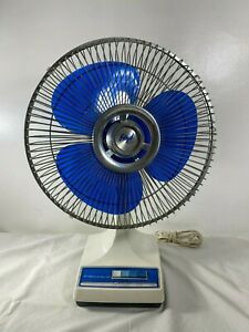
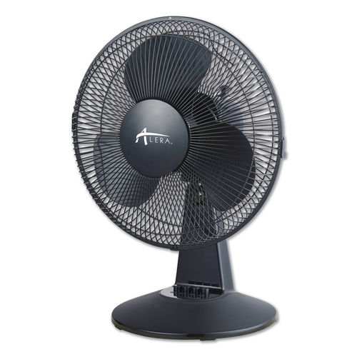
Desk or floor-standing fans are one of those appliances that will be present in almost every home or office. Some of the newer ones may already have remote control of some sort, while the older models won’t. It is however quite easy to do a retro-fitted controller to most of them, and at the same time, give them some (limited) intelligence.
Your typical oscillating fan does not have a lot of intelligence built-in. They normally consist of an electrical motor, with three separate windings, of varying inductance ( meaning the number of turns in the coil of wire will change the magnetic field generated, thereby changing the speed of the electric motor).
These windings have one common side, where all three of them are connected together, and the other three are separated. Normally the live wire from your mains supply (220v AC in my case) will go to this common connection. The neutral wire will go to the common of a four-position mechanical switch, with each winding going to one of positions 2,3 and 4 ( This results in a 3-speed configuration, with the first switch being off). It is also VERY important to note that this mechanical switch is hardware interlocked, meaning that ONLY one switch can be on at any given time… This is to ensure that electricity can only flow through one winding at a time. If you were to send electricity through multiple windings at the same time, the motor will still work, but not for very long…
In order to automate an oscillating fan, we would thus need a way to switch the separate windings on and off, while preventing other windings from getting power at the same time. I chose to do this with SPST relays, as a proof of concept, and plan to design it with DPDT relays at a later stage to implement a proper hardware interlock, in addition to the software interlock implemented in the control software ( more on that later)
My requirements for the device are the following:
1) Must operate from mains power, using the existing power cord of the fan.
2) Must allow for local operation of the fan using the existing control buttons.
3) Must be able to update firmware OTA, and have WiFi connectivity for control via Home Assistant or MQTT
4) Must be capable of adding support for ESP Now protocol at a later stage
5) The fan must not have any visible modifications on the outside
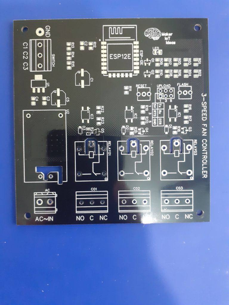
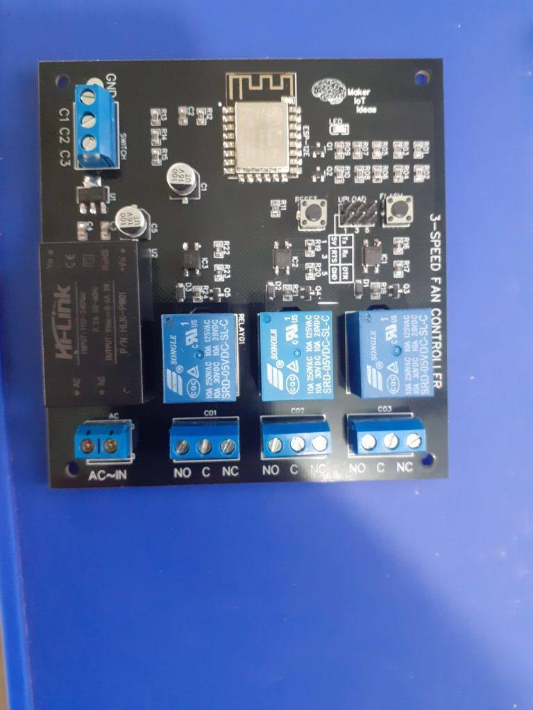
Taking all of my requirements into consideration, I have designed the following PCB to take care of my needs. As I do not require a lot of GPIO for this ( only 3 outputs, and 3 inputs ), I have decided to use an ESP8266-12E module from Espressif ( manufactured by AITinker, not sponsored by either company). This module is relatively cheap and has more than enough flash memory, RAM, as well as GPIO available.
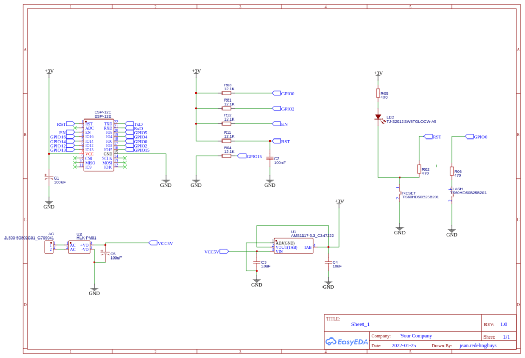
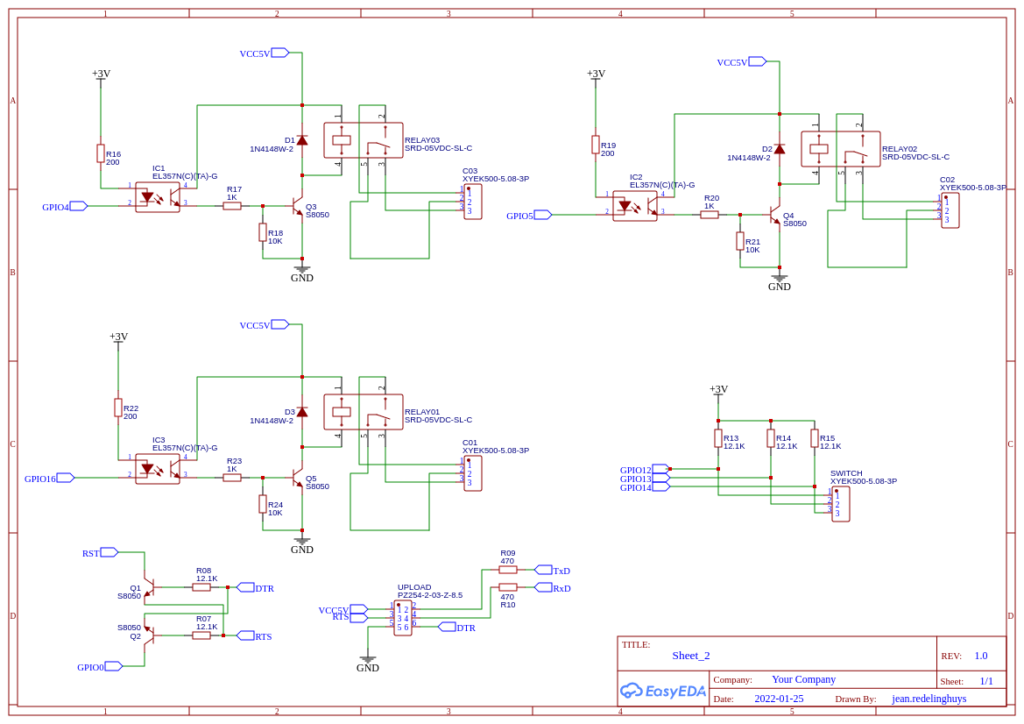
As we can see, the circuit is minimal, with optical isolation on the relay drivers, a programming header, and a 3-way input for the mechanical switch.
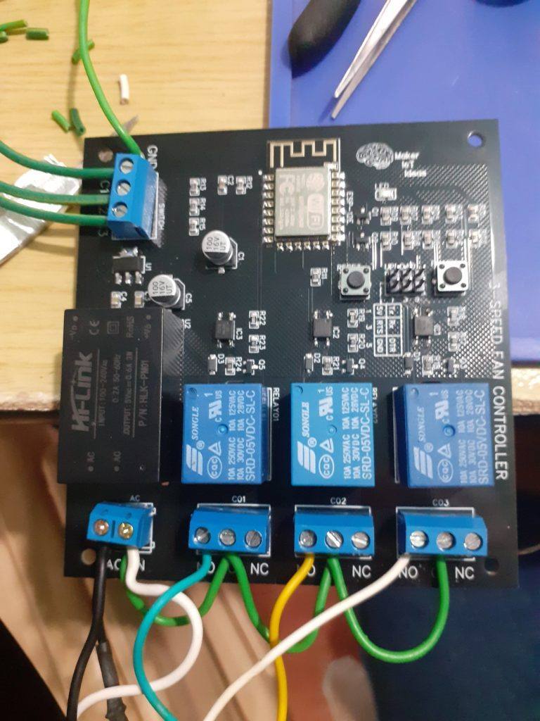
As seen in the picture above, the wiring is quite simple, with the neutral wire looped to the common terminal of each relay (I had only green mains rated cable available, will replace it later with a proper white cable to keep to wiring standards). Black is live, with one wire going to the mains socket, and the other to the common of the motor coil windings. Light blue, yellow and white ( connected to the N/O terminal of the relays) corresponds to speeds 1, 2 and 3 of the fan.
At the top of the board, 3 wires go to the mechanical switch and a fourth to DC ground. (Note that there is no AC voltage on any of the switches. )
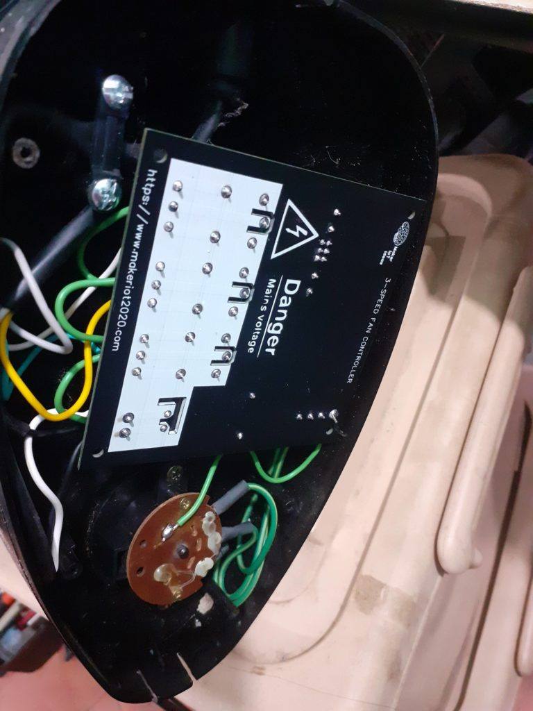
The PCB is mounted in the base of the fan while taking care to ensure that no AC cables are near the DC components. The ESP8266 chip is oriented to the side ( logo side of PCB ) to prevent interference to the WiFi signal. The mechanical switch is mounted into its original position, and its wires are routed away from any AC carrying wires to prevent interference.
It is important to note here that the firmware for the PCB was uploaded before assembly. You should NOT attempt serial uploading while the device is connected to mains power under any circumstances. ( While I have taken every precaution to ensure that AC and DC components of the circuit are separated from each other, it is just common sense to not try to upload firmware with mains connected)
Uploading firmware:
Initial uploading of firmware can be performed by connecting a USB-to-serial adapter to the UPLOAD port and providing 5v and ground from the USB-to-serial adapter. The flash button is held down, and the board is reset, after which you can proceed with uploading, alternatively, you can also connect the DTR and RTS lines from the serial adapter to automatically reset the board and enter flash mode as needed. ( If your adapter supports this of course).
ESPHome configuration
The YAML configuration for ESPHome is listed below:
esphome:
  name: esphome-web-18df94

esp8266:
  board: nodemcuv2


# Enable logging
logger:

# Enable Home Assistant API
api:

ota:


wifi:
  ssid: !secret wifi_ssid
  password: !secret wifi_password

  # Enable fallback hotspot (captive portal) in case wifi connection fails
  ap:
    ssid: "Esphome-Web-18Df94"
    password: "verysecurepassword"

captive_portal:

sensor:
  - platform: adc
    pin: VCC
    name: "ESP8266 Chip Voltage"
    id: mcu_voltage
    unit_of_measurement: "V"
    device_class: "voltage"
    accuracy_decimals: 2
    update_interval: 60s

  - platform: wifi_signal
    name: "WiFi Signal Sensor"
    id: wifi_strength
    device_class: "signal_strength"
    unit_of_measurement: "dBm"
    update_interval: 240s

binary_sensor:
  - platform: gpio
    pin:
      number: 12
      inverted: true
    name: "Fan Local Control Speed 1"
    id: "fan_local_1"
    icon: "mdi:fan-speed-1"
    filters:
      - delayed_on: 500ms
      - delayed_off: 500ms

    on_press:
      then:
        - switch.turn_on: speed1
    on_release:
      then:
        - switch.turn_off: speed1

  - platform: gpio
    pin:
      number: 13
      inverted: true
    name: "Fan Local Control Speed 2"
    id: "fan_local_2"
    icon: "mdi:fan-speed-2"
    filters:
      - delayed_on: 500ms
      - delayed_off: 500ms

    on_press:
      then:
        - switch.turn_on: speed2
    on_release:
      then:
        - switch.turn_off: speed2

  - platform: gpio
    pin:
      number: 14
      inverted: true
    name: "Fan Local Control Speed 3"
    id: "fan_local_3"
    icon: "mdi:fan-speed-3"
    filters:
      - delayed_on: 500ms
      - delayed_off: 500ms

    on_press:
      then:
        - switch.turn_on: speed3
    on_release:
      then:
        - switch.turn_off: speed3

switch:
  - platform: template
    name: "Fan Off"
    id: "fan_off"
    icon: "mdi:fan-off"
    lambda: |-
      if (id(speed1).state or id(speed2).state or id(speed3).state) {
        return false;
      } else {
        return true;
      }
    turn_on_action:
      - switch.turn_off: speed1
      - switch.turn_off: speed2
      - switch.turn_off: speed3


  - platform: gpio
    pin: 16
    interlock: &interlock_group [speed1, speed2, speed3]
    interlock_wait_time: 1000ms
    name: "Fan Speed 1"
    icon: "mdi:fan-speed-1"
    id: "speed1"
    inverted: true


  - platform: gpio
    pin: 5
    interlock: *interlock_group
    interlock_wait_time: 1000ms
    name: "Fan Speed 2"
    icon: "mdi:fan-speed-2"
    id: "speed2"
    inverted: true

  - platform: gpio
    pin: 4
    interlock: *interlock_group
    interlock_wait_time: 1000ms
    name: "Fan Speed 3"
    icon: "mdi:fan-speed-3"
    id: "speed3"
    inverted: true


Manufacturing the PCB
This PCB was manufactured at PCBWAY. The Gerber files and BOM, as well as all the schematics, will soon be available as a shared project on their website. If you would like to have PCBWAY manufacture one of your own, designs, or even this particular PCB, you need to do the following…
1) Click on this link
2) Create an account if you have not already got one of your own.
If you use the link above, you will also instantly receive a $5USD coupon, which you can use on your first or any other order later. (Disclaimer: I will earn a small referral fee from PCBWay. This referral fee will not affect the cost of your order, nor will you pay any part thereof.)
3) Once you have gone to their website, and created an account, or login with your existing account,

4) Click on PCB Instant Quote

5) If you do not have any very special requirements for your PCB, click on Quick-order PCB
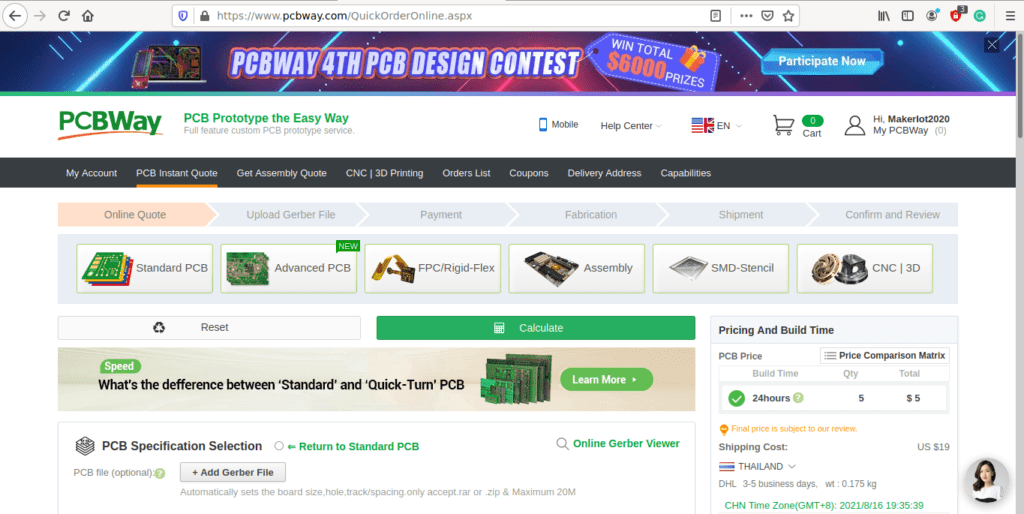
6) Click on Add Gerber File, and select your Gerber file(s) from your computer. Most of your PCB details will now be automatically selected, leaving you to only select the solder mask and silk-screen colour, as well as to remove the order number or not. You can of course fine-tune everything exactly as you want as well.


7) You can also select whether you want an SMD stencil, or have the board assembled after manufacturing. Please note that the assembly service, as well as the cost of your components, ARE NOT included in the initial quoted price. ( The quote will update depending on what options you select ).
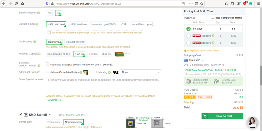

8) When you are happy with the options that you have selected, you can click on the Save to Cart Button. From here on, you can go to the top of the screen, click on Cart, make any payment(s) or use any coupons that you have in your account.
Then just sit back and wait for your new PCB to be delivered to your door via the shipping company that you have selected during checkout.