
This single cell lipo charger was created to solve a problem I encountered during a recent project. I constantly needed to recharge 18650 cells, and while I could also use my 4-cell charger, that didn’t always turn out to be the most practical. I also intend to use this small charger as a building block for a future complete power solution, including a boost converter, more protection features and proper cell status indication…
I am currently moving towards building more projects that will be used outside, “in the wild” and thus need a reliable way to power those. True to my way of doing things, I want to build my own stuff as far as possible. That way, I learn more about the technology, and I am sure that everything meets my exact specifications.
What is on the PCB?
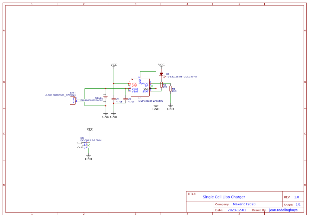
The charger is based on the MCP73832T, by Microchip, which contains quite a lot of useful features, in a small package as well at a relatively small price tag, and with very few other required supporting components.
- Linear Charge Management Controller:
- Integrated Pass Transistor
- Integrated Current Sense
- Reverse Discharge Protection
- High Accuracy Preset Voltage Regulation: + 0.75%
- Four Voltage Regulation Options:
- 4.20V, 4.35V, 4.40V, 4.50V
- Programmable Charge Current: 15 mA to 500 mA
- Selectable Preconditioning:
- 10%, 20%, 40%, or Disable
- Selectable End-of-Charge Control:
- 5%, 7.5%, 10%, or 20%
- Charge Status Output
- Tri-State Output – MCP73831
- Open-Drain Output – MCP73832
- Automatic Power-Down
- Thermal Regulation
- Temperature Range: -40°C to +85°C
- Packaging:
- 8-Lead, 2 mm x 3 mm DFN
- 5-Lead, SOT-23
A proper screw-type connection terminal on the output, as well as a DC Barrel Jack on the input, completes the PCB. On future revisions, I will seriously consider having a voltage-limiting circuit on the input side, since the MCP73832T is only capable of accepting an input voltage of up to 5.5v DC.
This is not a problem to me, as I will be using the current version for my own personal use. I do however believe it is essential to ensure that no over-voltage conditions can accidently occur BEFORE I will give this to someone else to use.
The schematic
Manufacturing the PCB
I choose PCBWay for my PCB manufacturing. Why? What makes them different from the rest?
PCBWay‘s business goal is to be the most professional PCB manufacturer for prototyping and low-volume production work in the world. With more than a decade in the business, they are committed to meeting the needs of their customers from different industries in terms of quality, delivery, cost-effectiveness and any other demanding requests. As one of the most experienced PCB manufacturers and SMT Assemblers in China, they pride themselves to be our (the Makers) best business partners, as well as good friends in every aspect of our PCB manufacturing needs. They strive to make our R&D work easy and hassle-free.
How do they do that?
PCBWay is NOT a broker. That means that they do all manufacturing and assembly themselves, cutting out all the middlemen, and saving us money.
PCBWay’s online quoting system gives a very detailed and accurate picture of all costs upfront, including components and assembly costs. This saves a lot of time and hassle.
PCBWay gives you one-on-one customer support, that answers you in 5 minutes ( from the Website chat ), or by email within a few hours ( from your personal account manager). Issues are really resolved very quickly, not that there are many anyway, but, as we are all human, it is nice to know that when a gremlin rears its head, you have someone to talk to who will do his/her best to resolve your issue as soon as possible.
Find out more here


Assembly and Testing
Assembly of this PCB was quite easy, providing that you have a stencil, it will not take you more than a few minutes.
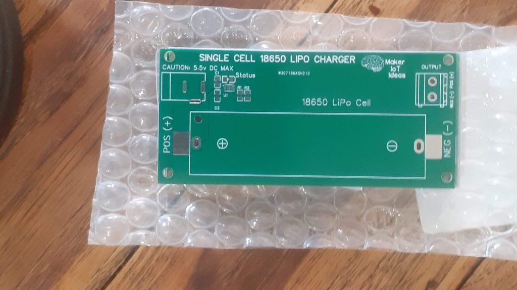
The PCB’s really came out very nicely 🙂
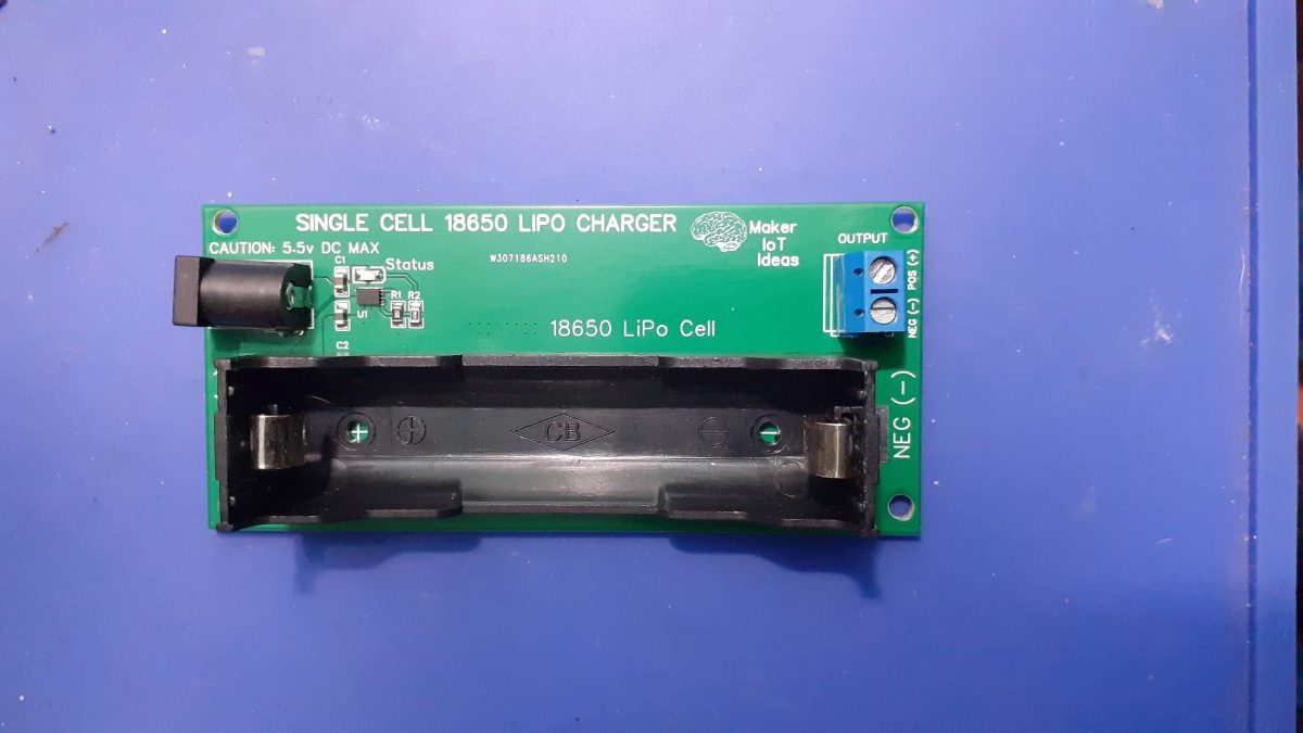
I have also made provision for using a through-hole 18650 battery holder, just in case you are like me, and have a few lying around in a drawer, or could just not be bothered with using the SMD version…
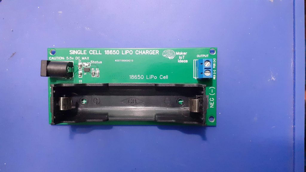
The completed PCB is relatively small and compact, taking into consideration the size of the 18650 cell of course… The screw terminal on the output really helps to keep everything secure when using the module to power a project, and the DC barrel jack provides a good connection to charge it all back up again…
Now, If I just remembered to add some form of voltage limiting on the input, as well as include a boost converter, It would be the perfect little “power bank” project… For now though, let’s leave those features to the future, as this is already extremely useful as is.