

A few weeks ago, I designed and built my own breadboard power module, mainly to try and solve some perceived problems with commercial ones, and also just to have something that is completely my own.
While that design does indeed work very well, I did however find a few tiny issues that still needed attention.
- Two fixed voltages, 3.3v and 5.0v
- 1A current limit per regulator
- PCB Heatsink design can be improved further, as there is still a bit too much heat at a high current draw – not much actually, but I like things running as cool as possible.

Other requirements that popped up were the ability to have more than two set voltages, as well as being able to send the full Vsupply to a power rail if I choose to do so…
Having a few LM317G variable voltage regulators lying around, left over from a previous project, I decided to use those. They can source an additional 500mA of current (1500mA in total) and also makes it quite easy to have variable voltages.
Voltage is set with two resistors, of which one is usually a variable resistor. This does however mean that you need a multimeter or other device capable of measuring voltage each time that you need a different voltage, as well as to determine at what voltage the device is currently set if you have not used it in a while…

The initial prototype is quite bulky at the moment, but I do plan to change that in the future when I am completely happy with the performance of the module
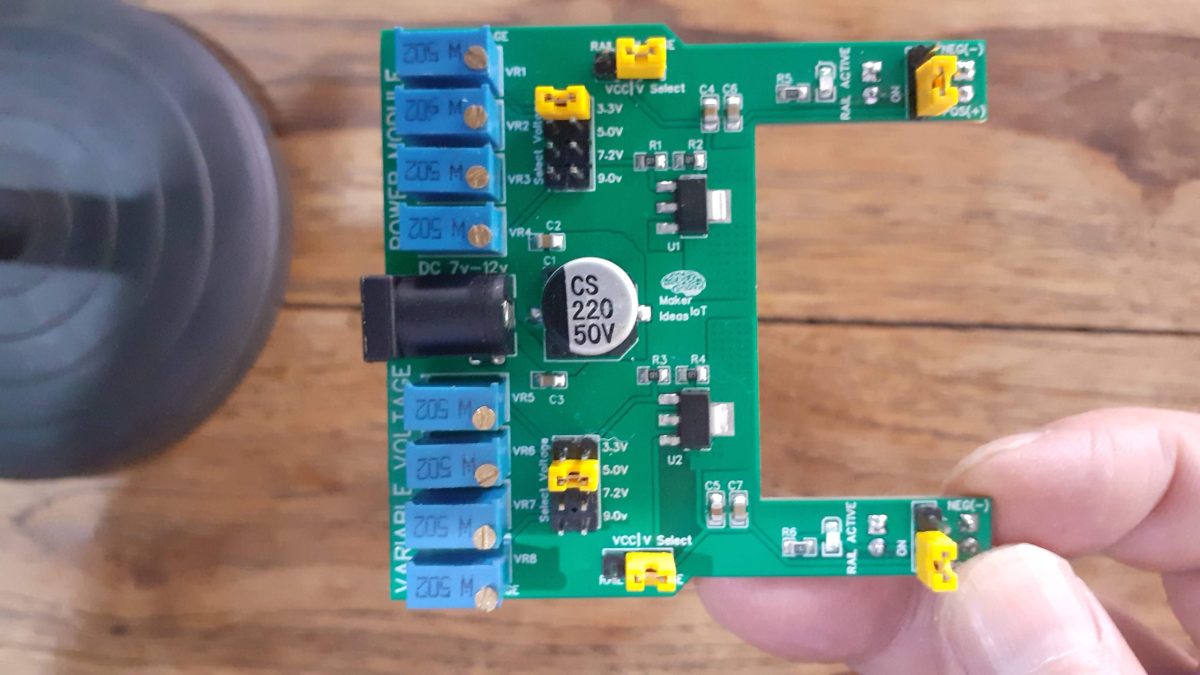
Each “voltage channel” consists of a 5k multiturn “trim pot” that connects back through a selectable jumper to a 240-ohm resistor ( I actually used two precision 120-ohm resistors in series) on the adjust pin of the regulator.
I have also reduced the number of smoothing capacitors on the input and outputs, as the voltages are quite stable
After assembly, it only takes a few minutes to adjust each “trim pot” to the correct value using a small screwdriver and a multimeter. Once set and verified, they can be locked using a drop of “lock-tight” or similar.
The eight “trim pots” sets the voltages as follows:
Top Rail:
VR1 – 3.3v
VR2 – 5.0v
VR3 – 7.2v
VR4 – 9.0v
Bottom Rail:
VR5 – 3.3v
VR6 – 5.0v
VR7 – 7.2v
VR8 – 9.0v
Turning the “pot” anti-clockwise reduces the voltage, while a clockwise movement increases it.
Changing voltages then becomes as easy as changing a jumper to a preset position.
The Schematic

As mentioned above, I have used two precision 120-ohm resistors on one leg of the resister divider that is connected to the adjust leg. Feel free to replace that with a single 240-ohm resistor and a 0-ohm bridge.
The multiturn precision 5k trim pots give great control and the desired voltages can be dialled in very accurately.
The module was designed as a double-layer PCB. I used big solid ground planes to provide good grounding, as well as serve as heat sinks for the voltage regulators.


Manufacturing
I choose PCBWay for my PCB manufacturing. Why? What makes them different from the rest?
PCBWay‘s business goal is to be the most professional PCB manufacturer for prototyping and low-volume production work in the world. With more than a decade in the business, they are committed to meeting the needs of their customers from different industries in terms of quality, delivery, cost-effectiveness and any other demanding requests. As one of the most experienced PCB manufacturers and SMT Assemblers in China, they pride themselves to be our (the Makers) best business partners, as well as good friends in every aspect of our PCB manufacturing needs. They strive to make our R&D work easy and hassle-free.
How do they do that?
PCBWay is NOT a broker. That means that they do all manufacturing and assembly themselves, cutting out all the middlemen, and saving us money.
PCBWay’s online quoting system gives a very detailed and accurate picture of all costs upfront, including components and assembly costs. This saves a lot of time and hassle.
PCBWay gives you one-on-one customer support, that answers you in 5 minutes ( from the Website chat ), or by email within a few hours ( from your personal account manager). Issues are really resolved very quickly, not that there are many anyway, but, as we are all human, it is nice to know that when a gremlin rears its head, you have someone to talk to that will do his/her best to resolve your issue as soon as possible.
Find out more here

Assembly
The assembly of this module is quite easy, no stencil is required. I recommend that you take care of the SMD components first, using hot -air or even hand soldering them, before assembling the through-hole components.
Here I do recommend that you use a breadboard to make sure that the 2.54mm headers that will connect to the power rails are lined up nicely
Testing and Setup
As already described above, the module does require a bit of setup after assembly. To do this, you will require a DC power supply with a voltage of 7v to 12v, as well as a multimeter, preferably with clips on the test leads, as well as a small terminal screwdriver.
- With the module powered, and the Rail Voltage jumpers set to VCC, measure the rail outputs with the multimeter ( remember that the rail active jumper MUST be set to on). Both rails should be at the same voltage as your VCC input voltage, ie 12v DC
- Move the Select Voltage jumper for both rails to the 3.3v position, and the Rail voltage jumper to the VSelect position for both rails.
- With the multimeter connected to each rail in turn, turn VR1 anti-clockwise until the voltage for the top rail is set to 3.3v. Repeat for the bottom rail, adjusting VR5 instead, while measuring the bottom rail.
- Repeat this step for each of the voltages, remember to power off the module before changing jumper positions – to prevent accidental short circuits…
Pictures

