This is a modification of my existing P-MOS driver circuits, intended for use with higher current LED Lights, as well as any other applications requiring a higher current capable P-Channel Mosfet to switch a load.
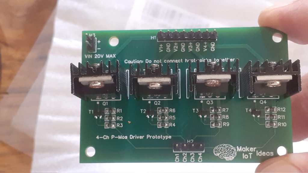
What is on the PCB?
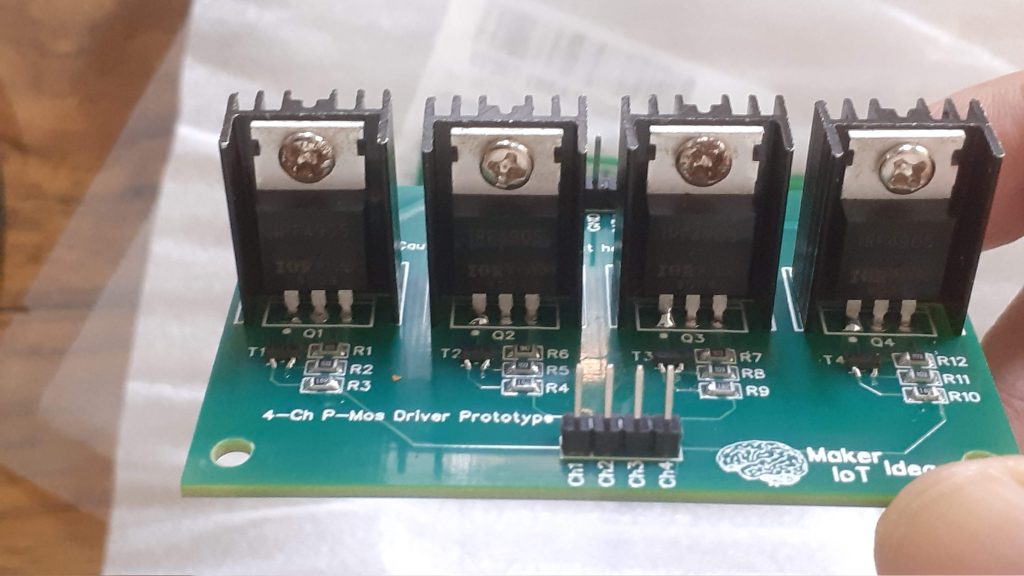
I have used the IRF4905 P-Channe Mosfet here as it can sink up to 74 Amps of current – A complete overkill in many situations. Datasheet. The Mosfet is configured in a high-side switching configuration, thus eliminating problems with ground connections.
To prevent unreliable switching, a transistor is used to switch the gate, which is normally pulled high to keep the device switched off.
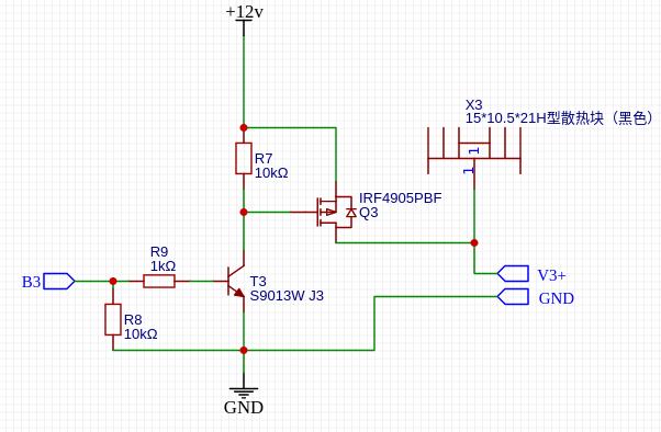
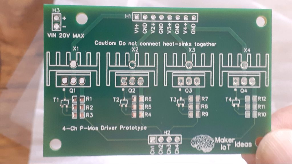
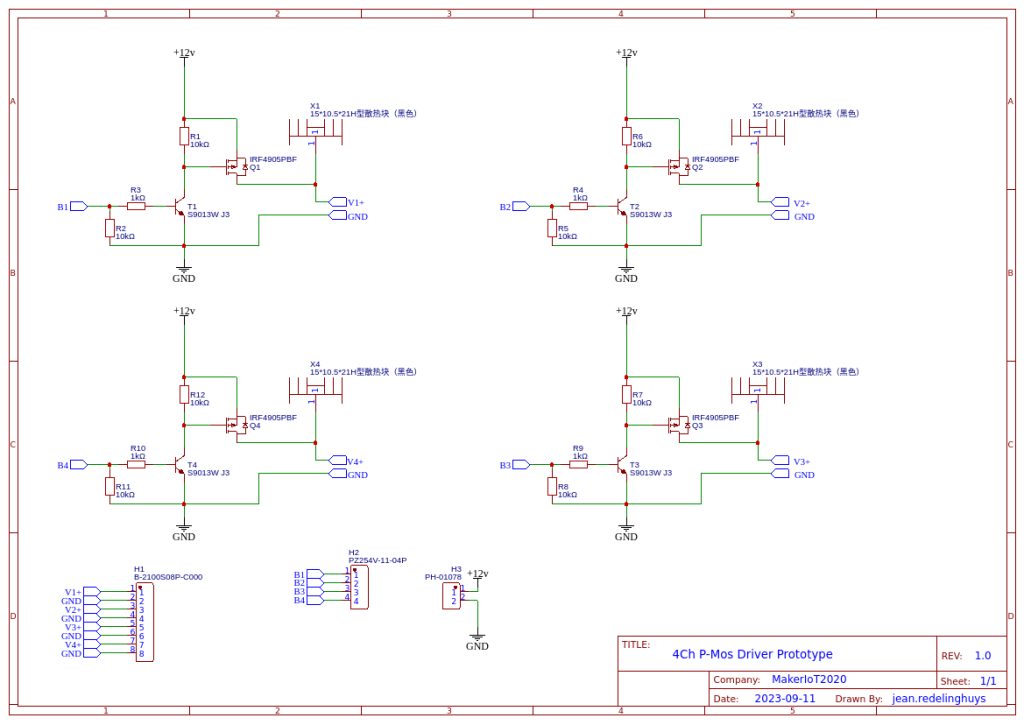
I have also included various connection headers for connecting the load, Power supply, as-well-as active high control headers for controlling the driver from a microcontroller. This was especially important as the Gate voltage of the Mosfet is above the acceptable 3.3 volt for use with many of the modern microcontrollers in use today.
It is important o note that I did not yet bother to do very accurate gate current calculations. I do not need super fast switching, and on the bench, the 500mA switching capability of the S9013W transistor gave me satisfactory results.
What is my intended use for this driver?
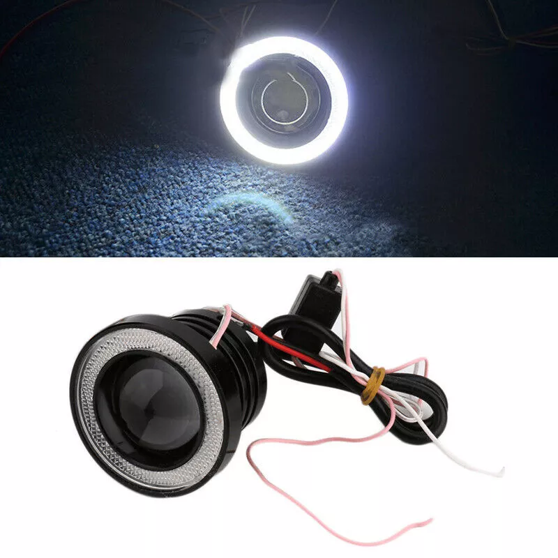
This is a 12v Automotive Fog light. It is meant to be an aftermarket upgrade. It will also be a very nice focused working light in my workshop, as the lighting is not optimal.
My initial idea is using two of these, PWM controlled from an ESPHome-controlled device to provide me with focused, dimmable lighting for assembly and other operations where a bit of extra light will be needed.
The Fish-eye lens of the internal lamp provides a very focused beam, and from initial testing seems to be exactly what I want.
The problem came in that the LED module consumes quite a bit of current ( 5A for the center lamp, and 3A for the ring light). These currents are way above the capabilities of my existing LED COB driver circuit, thus this MOD.
The Schematic
Manufacturing the PCB
I choose PCBWay for my PCB manufacturing. Why? What makes them different from the rest?
PCBWay‘s business goal is to be the most professional PCB manufacturer for prototyping and low-volume production work in the world. With more than a decade in the business, they are committed to meeting the needs of their customers from different industries in terms of quality, delivery, cost-effectiveness and any other demanding requests. As one of the most experienced PCB manufacturers and SMT Assemblers in China, they pride themselves to be our (the Makers) best business partners, as well as good friends in every aspect of our PCB manufacturing needs. They strive to make our R&D work easy and hassle-free.
How do they do that?
PCBWay is NOT a broker. That means that they do all manufacturing and assembly themselves, cutting out all the middlemen, and saving us money.
PCBWay’s online quoting system gives a very detailed and accurate picture of all costs upfront, including components and assembly costs. This saves a lot of time and hassle.
PCBWay gives you one-on-one customer support, that answers you in 5 minutes ( from the Website chat ), or by email within a few hours ( from your personal account manager). Issues are really resolved very quickly, not that there are many anyway, but, as we are all human, it is nice to know that when a gremlin rears its head, you have someone to talk to that will do his/her best to resolve your issue as soon as possible.
Find out more here

Assembly and Testing
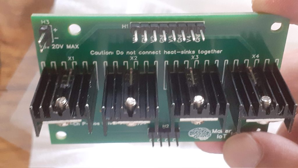
This PCB is definitely quite easy to assemble, as there are only 16 SMD components on the board. These are all easily hand-solderable. The Mosfets and their respective heatsinks are through-hole components and thus super easy as well.
It is very important to note that we should NOT connect the heatsinks together. This is due to the fact that the Heatsink is connected to the DRAIN pin on the MOSFET. Connecting them together will thus short the various channels together.
For my testing procedure, I have connected the driver to the LED Fog light, as well as a 12v supply. Using an ESP8266 running ESPHome, the LED fog light was controlled with PWM. The current draw was 5A and 3A respectively. All of the MOSFETs remained cool to the touch, and the PCB tracks did not heat up as well.
Next steps
The next steps for this project would be to design a PCB that integrates this driver with the ESPHome control device, as well as design and build a suitable enclosure for the two lights and the control unit. This should ideally be mountable on the ceiling above my workbench. It would also be nice to design some sort of gimbal for each light, that can be controlled with stepper motors or servo’s to allow me to position the lights where I need them.