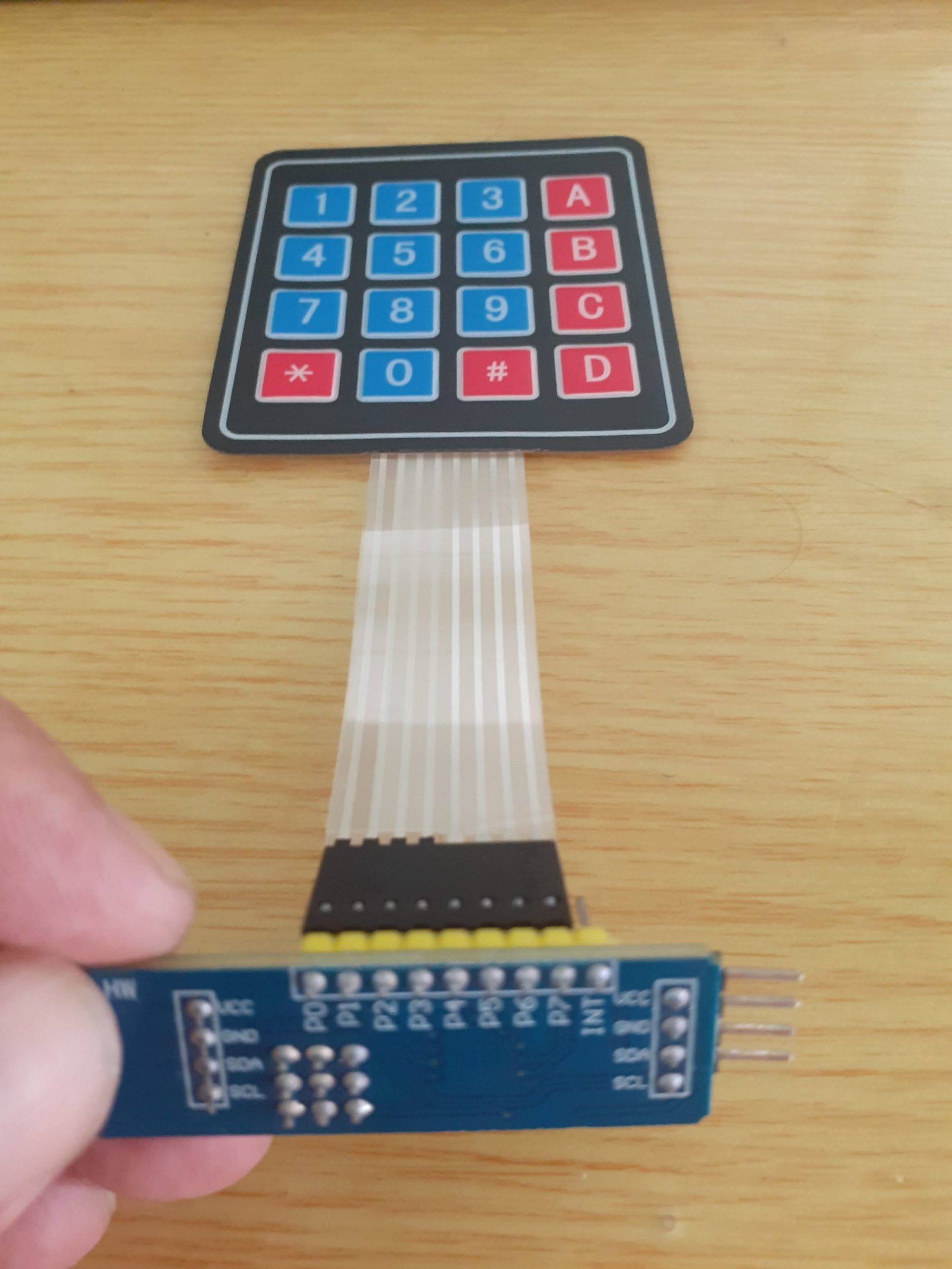
Using a matrix keypad is a very easy way to add multiple control buttons to a project, be it to enter a password, or to control different devices. These keypads do unfortunately have some serious flaws (in my view anyway)
1) They are usually of extremely low quality ( especially some of the membrane types from China). This means they dont last very long.
2) A typical 4×4 Matrix keypad will require 8 of your precious IO pins for itself.
These two flaws can however easily be solved, if we use a bit of technology, and are willing to to a bit of simple circuit construction by ourselves.
What does this mean ? Most of us makers will inevitably have a piece of proto-board or strip-board lying around, as well as a few momentary push-button switches. These can easily be used to make out own, much more reliable keypad. Let us look at the circuit
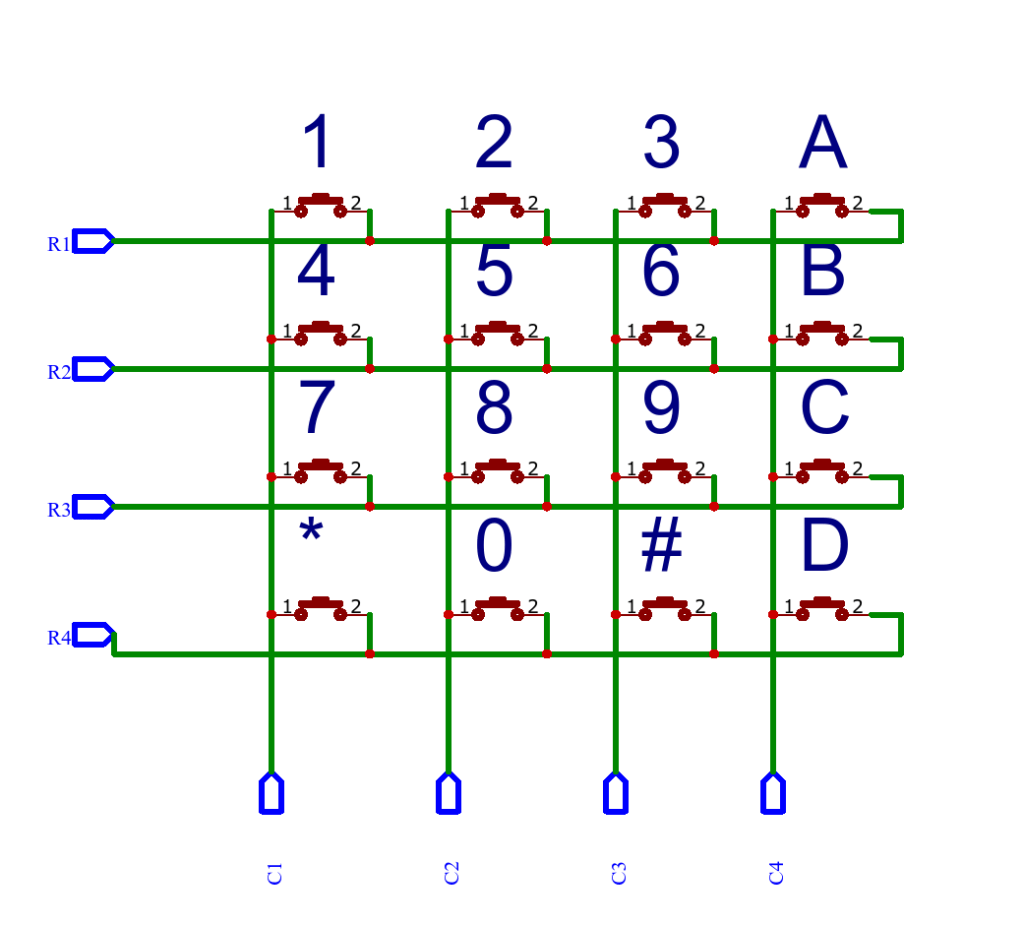
As we can see, to build a 4×4 matrix keypad, we will need 16 momentary switches. These are connected together as shown above. You can then interface it with your favourite micro-controller to read the key(s) pressed…
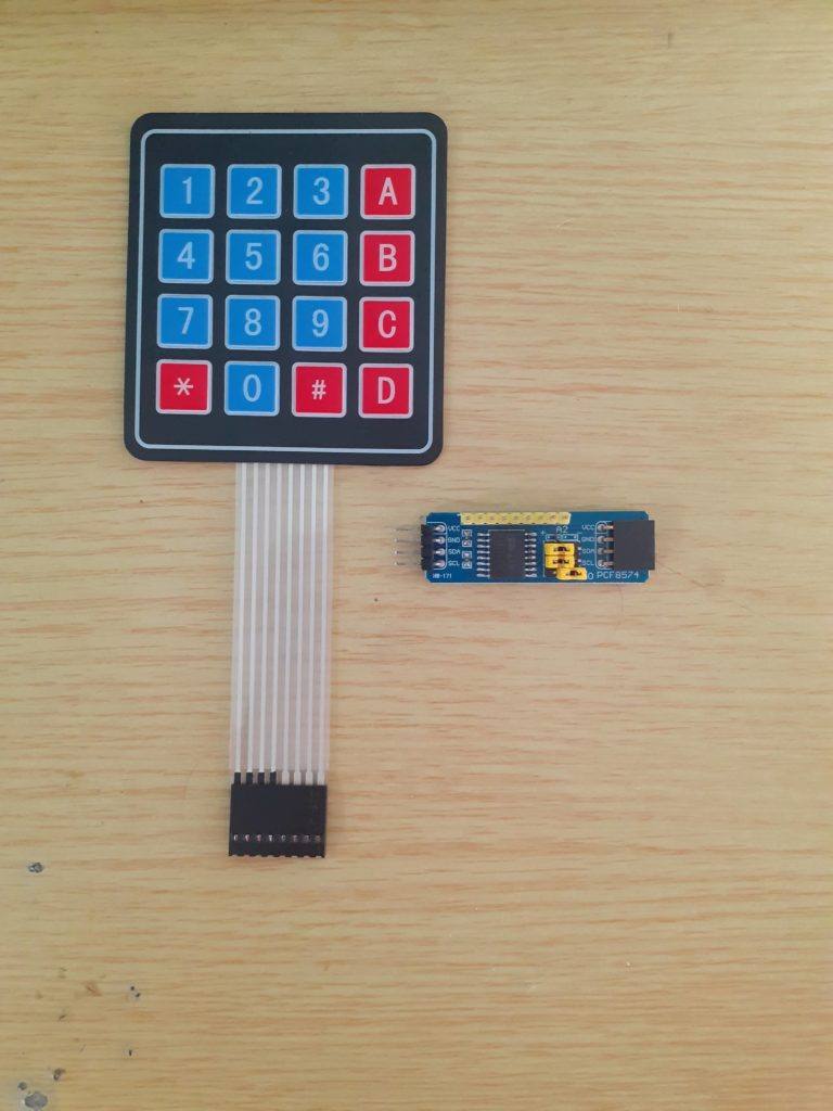
This definitely solves the first of my problems, but we still need 8 pins to control this keypad… or do we? No, we don’t, we need only 2 pins. That is to say if we use one of those PCF8574 I2C IO port expander modules. They are much more reliable, as well as quite cheap as well. all depending on where you buy them from, and how long you are willing to wait for shipping 🙂
Let us see how to connect the keypad to the I2C Module
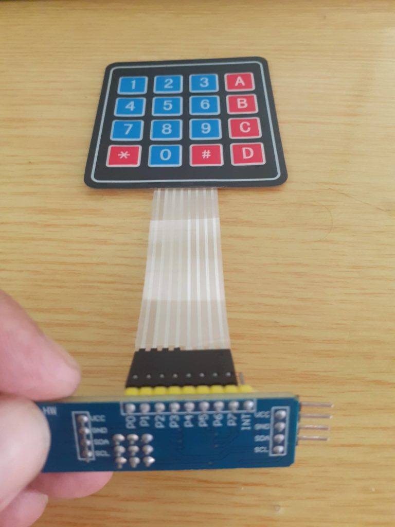
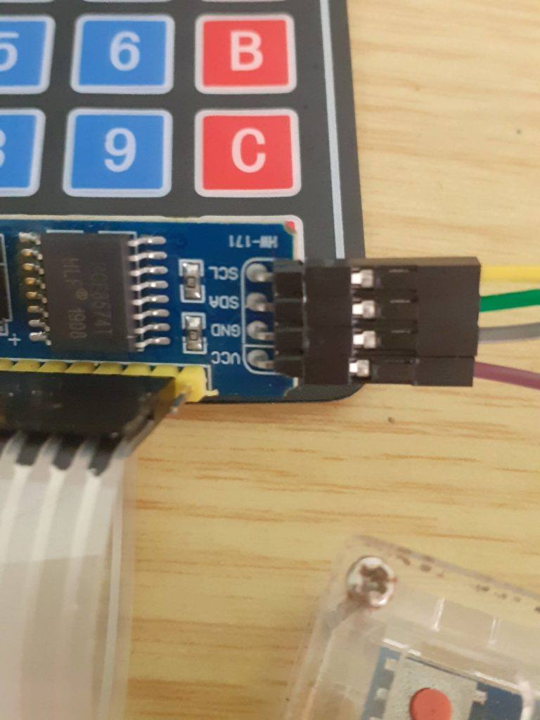
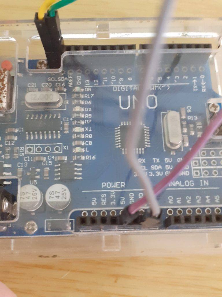
Now, we need to install some libraries
The first one is the actual Keypad library, you can download it from the link below
The second library that we will need, is the keypad_i2c library, once again, download it from the link below.
Coding the keypad
#include <Key.h>
#include <Keypad.h>
#include <Keypad_I2C.h>

#define I2CADDR 0x26 // Set the Address of the PCF8574

const byte ROWS = 4; // Set the number of Rows
const byte COLS = 4; // Set the number of Columns

// Set the Key at Use (4x4)
char keys [ROWS] [COLS] = {
  {'1', '2', '3', 'A'},
  {'4', '5', '6', 'B'},
  {'7', '8', '9', 'C'},
  {'*', '0', '#', 'D'}
};

// define active Pin (4x4)
byte rowPins [ROWS] = {0, 1, 2, 3}; // Connect to Keyboard Row Pin
byte colPins [COLS] = {4, 5, 6, 7}; // Connect to Pin column of keypad.

// makeKeymap (keys): Define Keymap
// rowPins:Set Pin to Keyboard Row
// colPins: Set Pin Column of Keypad
// ROWS: Set Number of Rows.
// COLS: Set the number of Columns
// I2CADDR: Set the Address for i2C
// PCF8574: Set the number IC
Keypad_I2C keypad (makeKeymap (keys), rowPins, colPins, ROWS, COLS, I2CADDR, PCF8574);

void setup () {
  Wire .begin (); // Call the connection Wire
  keypad.begin (makeKeymap (keys)); // Call the connection
  Serial.begin (9600);

}
void loop () {

  char key = keypad.getKey (); // Create a variable named key of type char to hold the characters pressed

  if (key) {// if the key variable contains
    Serial.println (key); // output characters from Serial Monitor
  }
}
Upload this to your Arduino device and enjoy. This sketch can also be adapted for 1×4, and 4×3 keypads, and with a little modification, will also work perfectly on ESP32 or ESP8266 as well…

