
USB-to-Serial converters are some of the most used modules on my bench. I have quite a few of them, most of them are the cheap online type that can be had for a few dollars.
As part of my new project, where I am seriously looking for an alternative chip to replace the ATMEGA328, which has become almost impossible to get, and super expensive when you do get it, I needed to get hold of a UPDI programmer.
There are many available online, from cheap to more expensive, but I wanted to build my own, as it did not seem too difficult to do.
As another part of my daily tasks, I also use a lot of ESP-type chips, which have a particular procedure to upload code via an external serial adapter.
The idea was thus to design a USB UART module that has multiple purposes, as well as being easy and cheap to assemble.
- Be able to program ATMEGA328 Chips via Serial
- Be able to be used as a standard USB-to-UART adapter
- Be a UPDI programmer
- Have a selectable target voltage between 3.3v and 5v
- Have all modem signals (RTS, CTS, DSR, DTR) broken out.
- Be able to auto-flash and reset an ESP32 or ESP8266 device, or similar

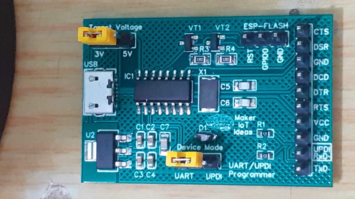
What is on the PCB?
The PCB is powered by the PC USB port. The target device voltage is selectable between 3.3v and 5v. The device mode can be changed from UART to UPDI mode with a jumper. An additional header specifically for ESP32/ESP8266 devices is provided, giving access to the FLASH and reset signals for the ESP device.
The USB to serial conversion is taken care of by a CH340G Chip, which provides all the relevant modem signals as well.
All signals, with the exception of the “RING” signal, are broken out onto the main header.
Note that there are NO status or POWER LEDs on the board. This was on purpose, as these sometimes interfere with the UPDI programming mode.

Prototype PCB – Assembled


Connecting to different devices
ESP32 or ESP8266 Devices
When in UART mode, the device can be used to upload code to an ESP32/ESP8266 automatically, similar to a standard dev board, without requiring you to press and flash and reset buttons.
This is achieved by connecting the device as follows:
UART MODULE SET to 3v
UART VCC to ESP 3v
UART GND to ESP GND
UART RX to ESP TX
UART TX to ESP RX
(Connections for Auto Upload/Reset)
UART RST ( on ESP-Flash Header) to ESP RST
UART GPIO0 ( on ESP-Flash Header) to ESP GPIO0
It will now be possible to flash and auto reset the connected ESP device from the Arduino IDE, and possibly others as well…
Arduino (Atmega 328P)
In the current version of the prototype, you have to connect it as follows:
UART Target voltage set to 3v or 5v depending on what type of board you are uploading
UART Tx to Arduino Rx
UART Rx to Arduino Tx
UART VCC to Arduino 3v or 5v ( depending on the target voltage required by the board you are flashing)
UART GND to Arduino GND
To allow for auto flash/reset on the Arduino, a 100nf capacitor is required between the UART DTR line and the Arduino Reset pin. This capacitor has NOT yet been fitted onto the PCB, as I usually use ICSP to upload these. Future versions of the PCB shall have this included.
ATMEGA4808/4809 and or ATTiny with UPDI Interface
This device is currently an LV-only UPDI programmer. Connections are as follows:
Set Target voltage on J1 of the UART/UPDI programmer.
Set The Device mode on J2 to UPDI mode
Connect VCC and GND from the Programmer to the target chip/board
Connect Programmer UPDI pin( shared with RxD) to Target UPDI pin.
General use UART for use as Serial monitor/Terminal
Set target voltage on J1
Set device mode to UART on J2
Connect VCC, GND from UART to the target device,
UART Tx to Target Rx
Uart Rx to Target Tx
Optionally connect required modem signals, RTS, CTS, DTR, and DSR as needed
Manufacturing
The PCB for this project has been manufactured at PCBWay.
Please consider supporting them if you would like your own copy of this PCB, or if you have any PCB of your own that you need to have manufactured.

Some Links to things used in the project
MakerIoT SMD Prototyping Breadboard
Order this PCB from PCBWay