
The ESP32-S is, at least in my opinion, one of the most versatile microcontrollers available to the Maker at this moment. It ticks almost all of my boxes for features required in a microcontroller, with a lot of gpio’s, WiFi, and Bluetooth, as well as a lot of storage space for code.
I do however have an issue with it, which I usually get around by designing a custom circuit board with a specific purpose. This is great for a project, but as most projects do not start on a custom-built circuit board, I am usually required to use a breadboard module. This is where my problems start. These modules are cumbersome to fit on a breadboard, to say the least, taking up a lot of space, and leaving very little space to connect to its pins with anything else.
Some of these modules do not even fit on the breadboard, making it necessary to hang one side off the breadboard or use two breadboards with a gap in the middle. I am quite sure many people can relate to this problem.
My second issue is that when you have done your breadboarding, and want to go to a permanent project, which does not always need a dedicated PCB, you are now required to either live with things on a breadboard, scary to say the least or have a “spider” with many modules and wires, in a box or partly on protoboard etc…

My solution
You can get your own copy here
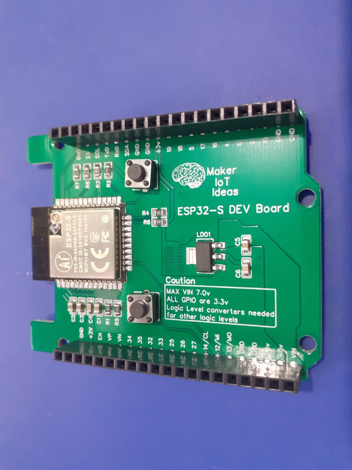
While not the most elegant, personally I really like the size, and layout of the humble Arduino Uno, with its standardised pinouts, and a large number of addon shields available for the platform. This made me think, sure, there are already ESP32-based boards in this form factor available commercially, but why not make my own instead, as well as a few of my most used modules in a standardised shield form, to make my life just that little bit easier?
The picture above shows my attempt, with most of the GPIO broken out onto female header pins (except for the 6 gpio that are connected to the internal flash chip on the module).


The PCB explained…
Power:
The board can be powered in two ways, either via the VIN pin ( at an optimal 7.0v DC – the LDO regulator can handle up to 15v, but I personally find that to stress it a bit hard ), which will use the onboard LDO voltage regulator to provide the needed 3.3v or from an external 3.3v PSU, which can provide a bit more current if needed…
There are also plenty of 3.3v and ground connections on the two 20-way headers to connect to other sensors.
Strapping Pins
All the required strapping pins are pulled up or pulled down, as per the datasheet, to 3.3v or ground respectively.
GPIO Pins
All GPIO pins are clearly labelled on the silkscreen to make it easier to use.
I did however not stick to the Arduino labelling convention, as I don’t always use the Arduino IDE, and the actual GPIO numbers are in my view, more useful then.
Flashing code to the board
It will be quite obvious that I did not include any USB-to-serial converter on the board, the reason for this being that, in my opinion,
1) it wastes space on the board
2) it is not actually necessary, as we can upload with an external uart adapter, or use OTA ( which I actually do most of the time )
3) In an actual project, that USB port is going to attract problems, especially if you give it to someone else to use…
A simple Arduino OTA sketch is available in the examples section of the Arduino IDE. It is easy to use and modify and does not need a lot to make it useable with your own sketch…
Antenna Cutout
As recommended by the manufacturer , I have chosen to place the chip inside a cutout on the top of the PCB, with no tracks nearby.

Although this is not the ideal “best position”, I found that this position worked well with previous designs, and have thus kept it at that.
General comments
As this board is mainly designed for prototype development, I did not bother with dedicated power connectors etc. I did however add proper wide tracks for all the power connections, an on-PCB-heatsink for the voltage regulator, as well as proper ground planes on both sides of the PCB, connected together with via-stitching where needed.
It is also very important to note that this is a 3.3v device. If you need to use sensors or peripherals that operate at other voltages, you will have to use external level converters.
Some assembly pictures


Schematic

Manufacturing
The PCB for this project has been manufactured at PCBWay.
Please consider supporting them if you would like your own copy of this PCB, or if you have any PCB of your own that you need to have manufactured.
You can get your own copy here
