Welcome to Part two of my RPi Pico Series. You can buy yours from Cytron Technologies.
In this post, we will look at some more of the features of the board, as well as how to get started using this development board. I will focus on MicroPython in this post, and cover C/C++ in the next post.
But before we do that, lets run over some of the specifications of the board first…
The Python Stuff will be at the end of this post…
Board Specifications
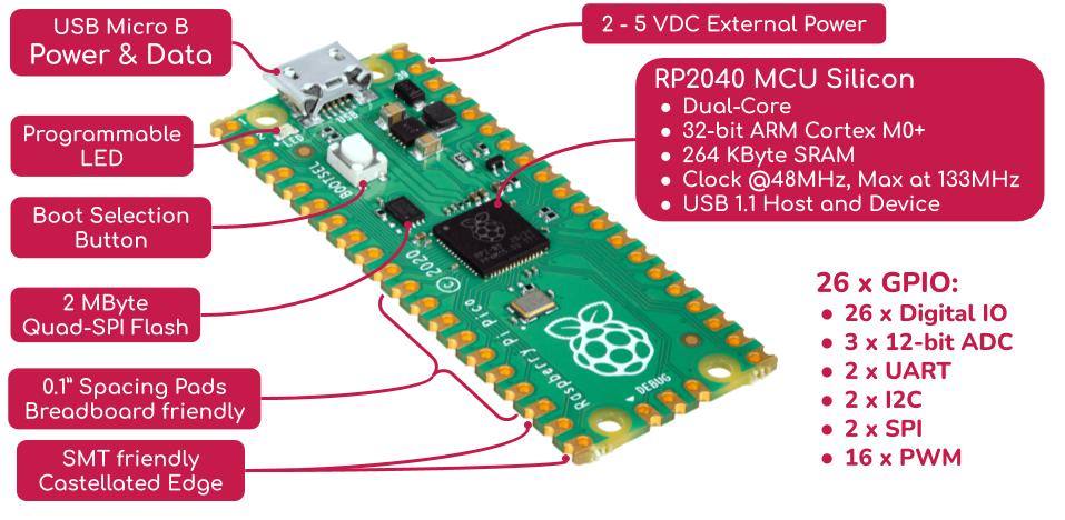
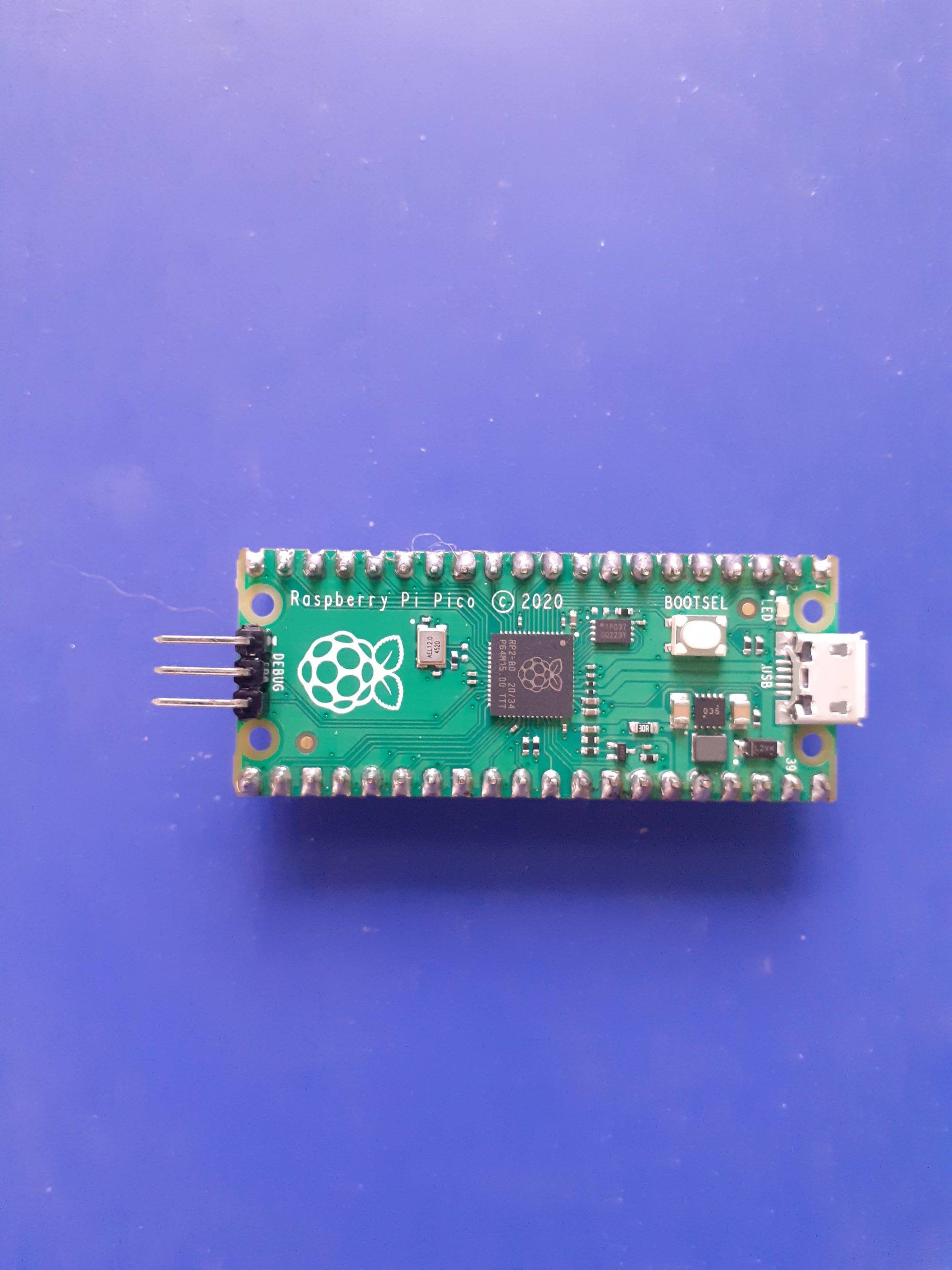
Raspberry Pi Pico is a low-cost, high-performance microcontroller board with flexible digital interfaces. Key features include:
- RP2040 microcontroller chip designed by Raspberry Pi in the United Kingdom
- Dual-core Arm Cortex M0+ processor, flexible clock running up to 133 MHz
- 264KB of SRAM, and 2MB of on-board Flash memory
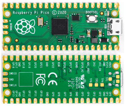
- Castellated module allows soldering direct to carrier boards
- USB 1.1 with device and host support
- Low-power sleep and dormant modes
- Drag-and-drop programming using mass storage over USB
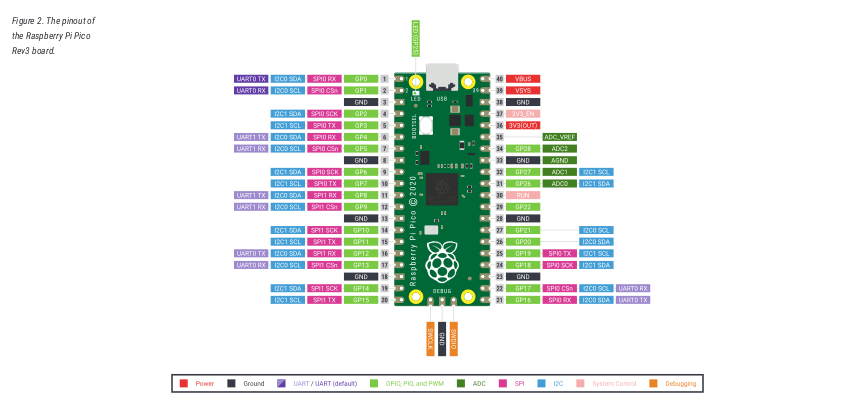
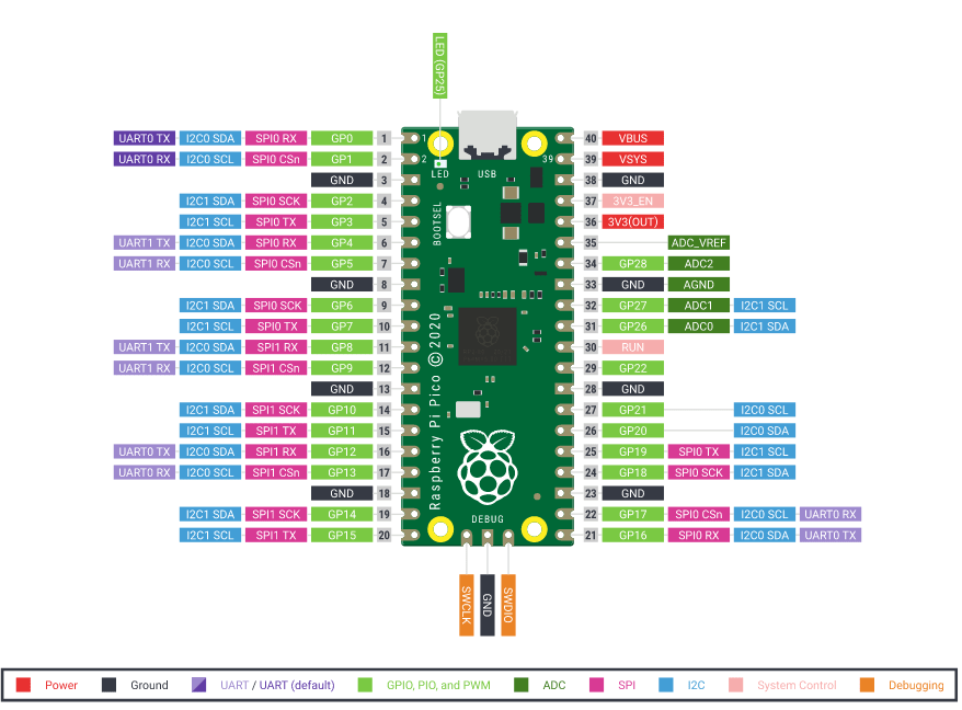
- 26 × multi-function GPIO pins
- 2 × SPI, 2 × I2C, 2 × UART, 3 × 12-bit ADC, 16 × controllable PWM channels
- Accurate clock and timer on-chip
- Temperature sensor
- Accelerated floating-point libraries on-chip
- 8 × Programmable I/O (PIO) state machines for custom peripheral support
Utilities
What is on your Pico?
If you have forgotten what has been programmed into your Raspberry Pi Pico, and the program was built using our Pico C/C++ SDK, it will usually have a name and other useful information embedded into the binary. You can use the Picotool command line utility to find out these details. Full instructions on how to use Picotool to do this are available in the ‘getting started‘ documentation.
Debugging using another Raspberry Pi Pico
It is possible to use one Raspberry Pi Pico to debug another Pico. This is possible via picoprobe, an application that allows a Pico to act as a USB → SWD and UART converter. This makes it easy to use a Pico on non-Raspberry Pi platforms such as Windows, Mac, and Linux computers where you don’t have GPIOs to connect directly to your Pico. Full instructions on how to use Picoprobe to do this are available in the ‘getting started‘ documentation.
Resetting Flash memory
Pico’s BOOTSEL mode lives in read-only memory inside the RP2040 chip, and can’t be overwritten accidentally. No matter what, if you hold down the BOOTSEL button when you plug in your Pico, it will appear as a drive onto which you can drag a new UF2 file. There is no way to brick the board through software. However, there are some circumstances where you might want to make sure your Flash memory is empty. You can do this by dragging and dropping a special UF2 binary onto your Pico when it is in mass storage mode.
The Code for the flash eraser is available below
/**
 * Copyright (c) 2020 Raspberry Pi (Trading) Ltd.
 *
 * SPDX-License-Iden
/**
 * Copyright (c) 2020 Raspberry Pi (Trading) Ltd.
 *
 * SPDX-License-Identifier: BSD-3-Clause
 */

// Obliterate the contents of flash. This is a silly thing to do if you are
// trying to run this program from flash, so you should really load and run
// directly from SRAM. You can enable RAM-only builds for all targets by doing:
//
// cmake -DPICO_NO_FLASH=1 ..
//
// in your build directory. We've also forced no-flash builds for this app in
// particular by adding:
//
// pico_set_binary_type(flash_nuke no_flash)
//
// To the CMakeLists.txt app for this file. Just to be sure, we can check the
// define:
#if !PICO_NO_FLASH
#error "This example must be built to run from SRAM!"
#endif

#include "pico/stdlib.h"
#include "hardware/flash.h"
#include "pico/bootrom.h"

int main() {
    flash_range_erase(0, PICO_FLASH_SIZE_BYTES);
    // Leave an eyecatcher pattern in the first page of flash so picotool can
    // more easily check the size:
    static const uint8_t eyecatcher[FLASH_PAGE_SIZE] = "NUKE";
    flash_range_program(0, eyecatcher, FLASH_PAGE_SIZE);

    // Flash LED for success
    gpio_init(PICO_DEFAULT_LED_PIN);
    gpio_set_dir(PICO_DEFAULT_LED_PIN, GPIO_OUT);
    for (int i = 0; i < 3; ++i) {
        gpio_put(PICO_DEFAULT_LED_PIN, 1);
        sleep_ms(100);
        gpio_put(PICO_DEFAULT_LED_PIN, 0);
        sleep_ms(100);
    }

    // Pop back up as an MSD drive
    reset_usb_boot(0, 0);
}tifier: BSD-3-Clause
 */

// Obliterate the contents of flash. This is a silly thing to do if you are
// trying to run this program from flash, so you should really load and run
// directly from SRAM. You can enable RAM-only builds for all targets by doing:
//
// cmake -DPICO_NO_FLASH=1 ..
//
// in your build directory. We've also forced no-flash builds for this app in
// particular by adding:
//
// pico_set_binary_type(flash_nuke no_flash)
//
// To the CMakeLists.txt app for this file. Just to be sure, we can check the
// define:
#if !PICO_NO_FLASH
#error "This example must be built to run from SRAM!"
#endif

#include "pico/stdlib.h"
#include "hardware/flash.h"
#include "pico/bootrom.h"

int main() {
    flash_range_erase(0, PICO_FLASH_SIZE_BYTES);
    // Leave an eyecatcher pattern in the first page of flash so picotool can
    // more easily check the size:
    static const uint8_t eyecatcher[FLASH_PAGE_SIZE] = "NUKE";
    flash_range_program(0, eyecatcher, FLASH_PAGE_SIZE);

    // Flash LED for success
    gpio_init(PICO_DEFAULT_LED_PIN);
    gpio_set_dir(PICO_DEFAULT_LED_PIN, GPIO_OUT);
    for (int i = 0; i < 3; ++i) {
        gpio_put(PICO_DEFAULT_LED_PIN, 1);
        sleep_ms(100);
        gpio_put(PICO_DEFAULT_LED_PIN, 0);
        sleep_ms(100);
    }

    // Pop back up as an MSD drive
    reset_usb_boot(0, 0);
}
Getting Started with MicroPython on the RPi Pico
Drag and drop MicroPython
You can program your Pico by connecting it to a computer via USB, then dragging and dropping a file onto it, so we’ve put together a downloadable UF2 file to let you install MicroPython more easily. Following the procedure below, you can install MicroPython onto the Pico in a few seconds…
1. Download and unzip the UF2 file below into a folder on your computer.
2. Hold down the Bootsel button on the Pico, and connect it to a USB cable that was already connected to your computer. ( This means, connect ons side of the usb cable to the computer, but dont connect the Pico yet. then hold down BOOTSEL, and connect the cable to the pico)
3. Now, release the BootSEL button
4. After a few Seconds, you will have a new USB storage device on your computer, called RPI-RP2
5. Drag the UF2 file into this USB Storage device. The Pico will reboot… You have now installed MicroPython on your RPi Pico
Accessing the MicroPython REPL
You can now access REPL from a serial terminal, or a MicroPython IDE , like Thonny…
I will show you how to do it from the Linux Terminal below.
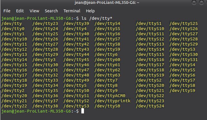
The Pico will show up as a USB device called ttyACM0
you can find it by issuing the ls /dev/tty* command
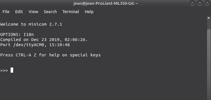
Start minicom or your preferred serial terminal emulator
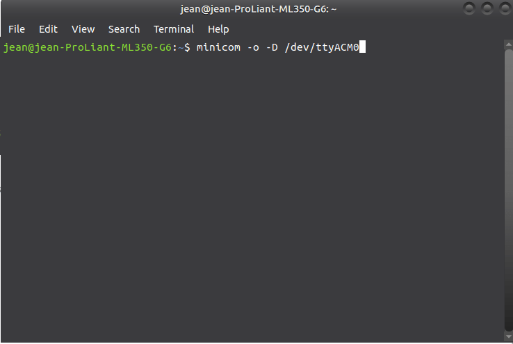
Press enter a few times, and you should get a REPL prompt
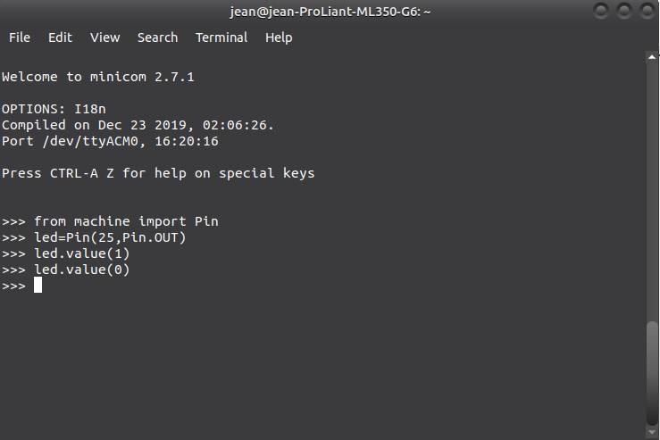
You can now test MicroPython on your Pico, by typing the following commands:
The complete MicroPython SDK for the RPi Pico is available for download at the link below…
In the next part of this series, we will look at using the Thonny IDE, as well as C/C++ to program the Pico