
In this almost post we look at the power distribution PCB for the almost completed Robotic Toy Car. I had many interesting issues to solve here, especially since I did not design my own Lipo battery charger circuit, but used a very useful little commercially available unit instead, the MH-CD42
Based on a relatively difficult chip to get information on, the module is basically an integrated Lipo charge/discharge module, with a built-in boost converter that provides 5v at a maximum of 2A current. What makes it special is the ability to simultaneously provide current and voltage, as well as charge the attached LiPo cell at the same time, when connected to an external charger.
It does, however, in my view at least, also have a few serious flaws, the most irritating of these being that it will completely discharge the attached LiPo cell even when completely switched off…
I have thus tried to stop this issue from occurring by adding a switch in line with the Lipo Cell, a quite obvious solution, but it should not have been needed if the chip functioned as intended… ( As far as I can gather, the module was originally designed to be used in USB power banks. This makes the flaw even more serious, as a self-discharging power bank really defeats the purpose)
Enough of that though, when it does work, it works great. just remember that you can not apply more than 5.5v DC to the charging input of the module.

The Schematic
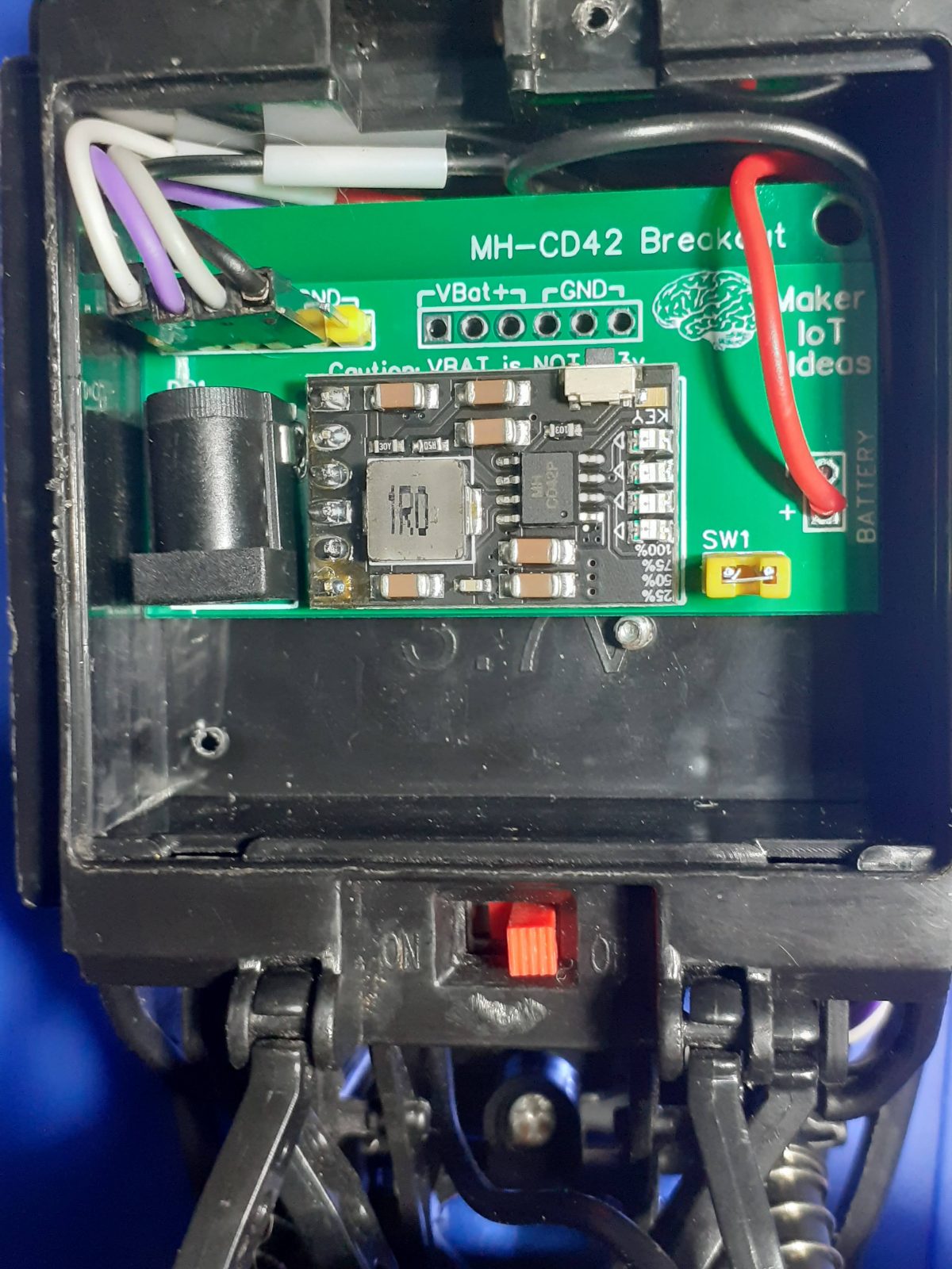
There is actually not a lot going on here, as everything is already on the supplied module. I have just added a charging port, additional power headers for 5v output and ground, as well as direct access to the LiPo Cell output, and a switch header to cut off power to the MH-CD42 when it is not in use.

The PCB
The PCB was manufactured as a 2-layer FR-4 board. The entire top layer is used as a ground plane, and the bottom layer was used for the 5v and Vbat traces, which were made as big as possible to allow for the high current ( up to 2A ) that the unit can supply to a load.


It is also worth mentioning that the VBAT pins are NOT 3.3v ( Remember that the LiPo cell can run from 4.2v down to 3.0v depending on the charge. These headers were only placed on the board to provide direct access to the LiPo cell, for use with for example an ADC input or for connection to a dev board that is already fitted with a buck converter or a suitable LDO voltage regulator.


Manufacturing the PCB
Over the past eight years, PCBWay has continuously upgraded their MANUFACTURING plants and equipment to meet higher quality requirements, and now THEY also provide OEM services to build your products from ideas to mass production and access to the market.
The PCB for this project has been manufactured at PCBWay.
Please consider supporting them if you would like your own copy of this PCB, or if you have any PCB of your own that you need to have manufactured.

If you would like to have PCBWAY manufacture one of your own, designs, or even this particular PCB, you need to do the following…
1) Click on this link
2) Create an account if you have not already got one of your own.
If you use the link above, you will also instantly receive a $5USD coupon, which you can use on your first or any other order later. (Disclaimer: I will earn a small referral fee from PCBWay. This referral fee will not affect the cost of your order, nor will you pay any part thereof.)
3) Once you have gone to their website, and created an account, or login with your existing account,

4) Click on PCB Instant Quote

5) If you do not have any very special requirements for your PCB, click on Quick-order PCB

6) Click on Add Gerber File, and select your Gerber file(s) from your computer. Most of your PCB details will now be automatically selected, leaving you to only select the solder mask and silk-screen colour, as well as to remove the order number or not. You can of course fine-tune everything exactly as you want as well.


7) You can also select whether you want an SMD stencil, or have the board assembled after manufacturing. Please note that the assembly service, as well as the cost of your components, ARE NOT included in the initial quoted price. ( The quote will update depending on what options you select ).

8) When you are happy with the options that you have selected, you can click on the Save to Cart Button. From here on, you can go to the top of the screen, click on Cart, make any payment(s) or use any coupons that you have in your account.
Then just sit back and wait for your new PCB to be delivered to your door via the shipping company that you have selected during checkout.