
`Ai-Thinker (#notsponsored) should be quite well known to many makers as a company that manufactured and designs many of the modules that we use in our projects. We, MakerIoT2020, definitely make use of quite a few of their products, like the RA-02, as well as their ESP32-S module.
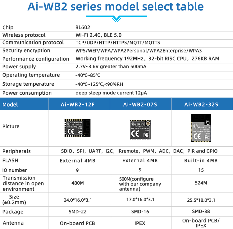
A few months ago, I got the opportunity to play with one of their newest projects, the AI-WB2, which is based on the BL602 Risc-V Chip. After a very very bumpy ride, mainly due to the chip being quite new, and documentation being virtually nonexistent in the English language, I decided to take a step back, and stop trying to reinvent the wheel 🙂 Afterall, I don’t want to use Apache NuttX or a similar RTOS for every project, as the thought of having to write almost all of the different required components from scratch, does not really appeal to me. especially as the SDK is in Chinese, and the English version of it is a bit patchy, to say the least…
This made me quite a bit frustrated, at least until I decided to change my thinking, and take a look at the stock AT command set that comes shipped on the modules from the factory… While excellent for use as a WiFi modem, it did not seem to allow any access to any of the GPIO on the WB-AI2 module… But wait… is that really a problem? No… Let me tell you why…
I also have a few XIAO Modules ( the RP2040 and SAMD21 ) lying around, and those do not have any connectivity options onboard…
A few very quick tests later, It was clear that the AI-WB2 will be a very compact
WiFi as well as BTLE connectivity solution for these XIAO modules, and, If I design with the future in mind, the GPIO pins of the AI-WB2 module can also become useable to me as well… once the firmware and SDK gets more accessible..
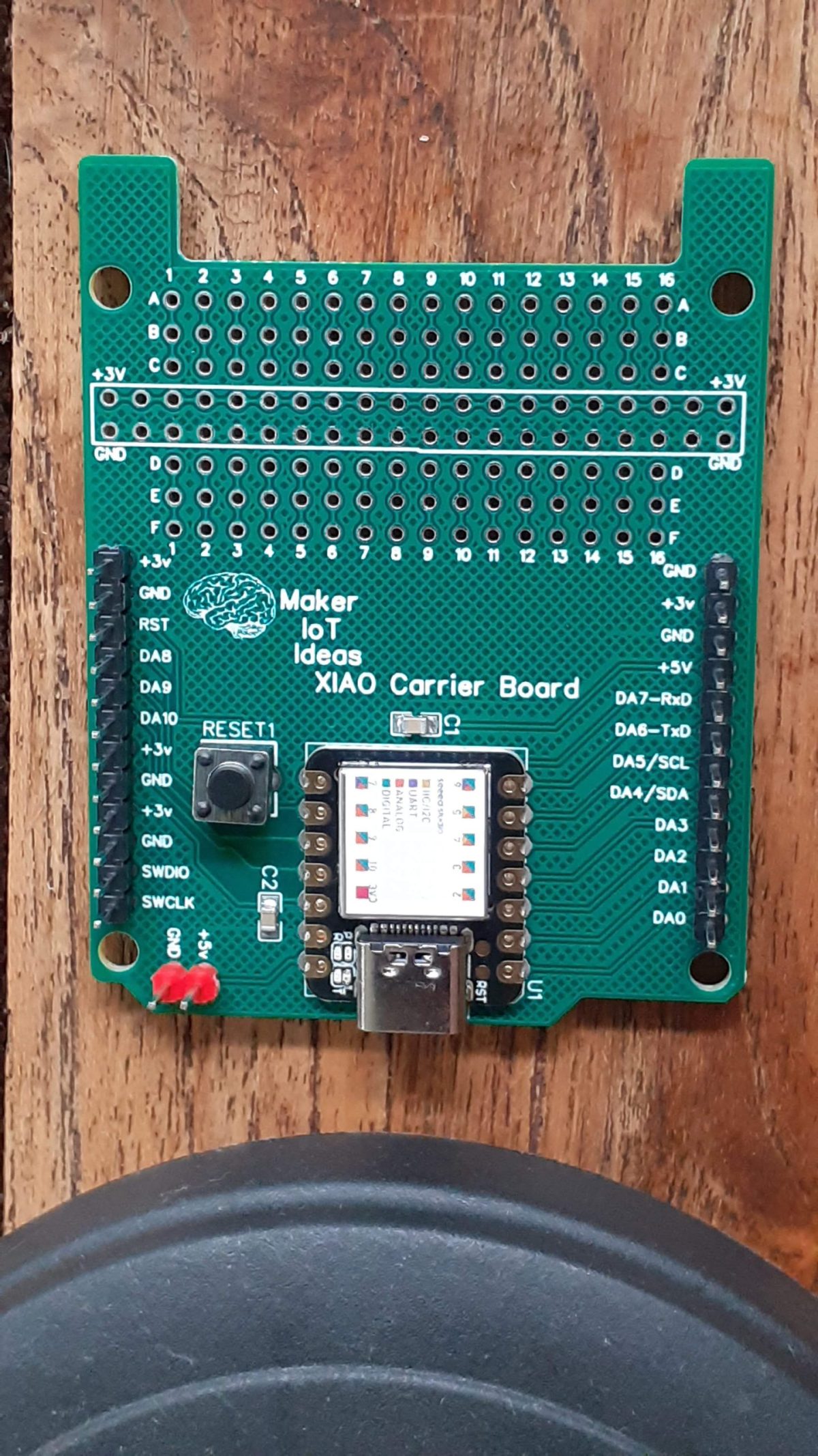
What followed from this is a very basic prototype PCB, with the XIAO RP2040 as the main processor, and the AI-WB2-12F as a “connectivity co-processor”, meaning that all communications functions will be offloaded to the AI-WB2 and the results of those, sent back to the XIAO for processing…
This in itself presents quite a few challenges, especially on the communications handling, and using the second UART port, which is currently not possible with the official Arduino Core for the RP2040… Luckily, the XIAO RP2040 uses an alternative core, that supports the second UART port quite well …
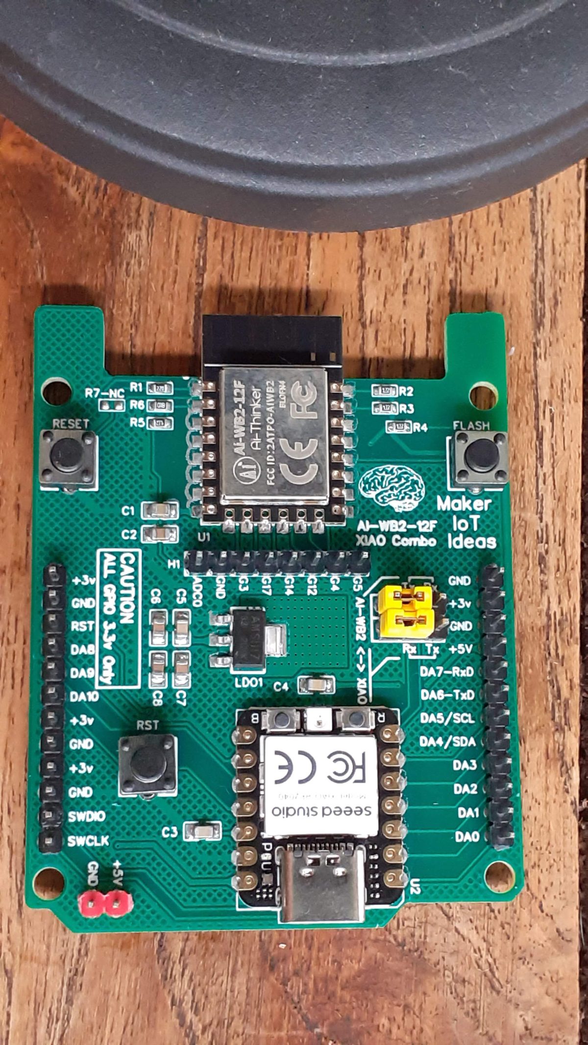
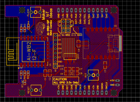
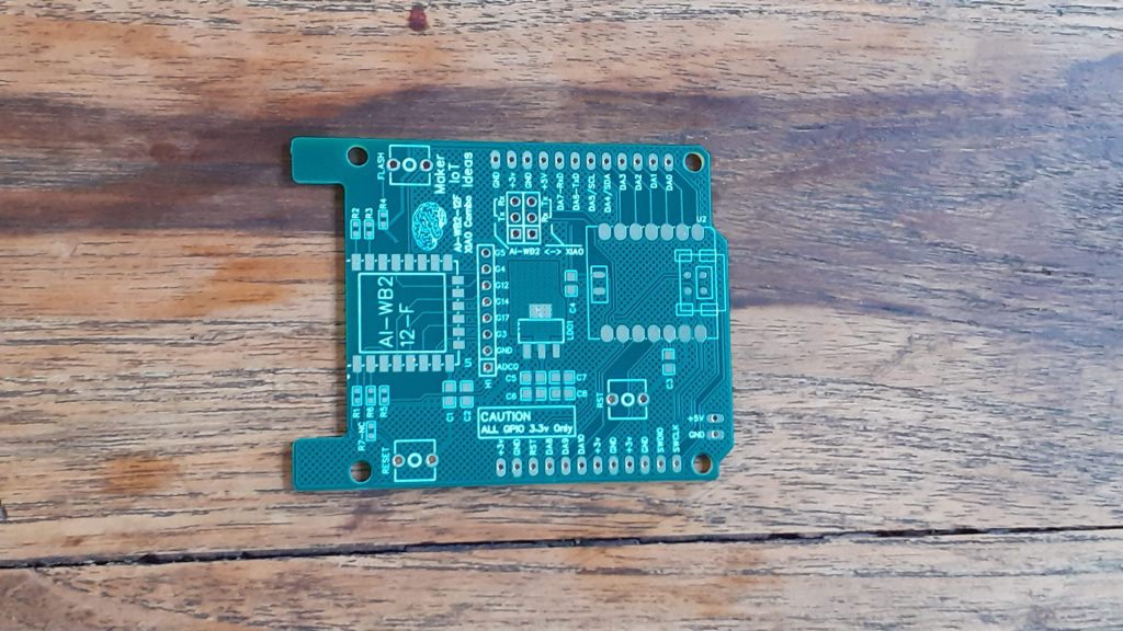
What is on the PCB?
The Top Section of the PCB is dedicated to the AI-WB2-12F and its supporting components, including a flash and reset button. The GPIO for the WB2-12F is broken out onto H1.
At the right, below H1, is a series of jumpers, connecting the Xiao RP2040 and WB2-12-F Uart ports, or, alternatively, connecting the XIAO Rp2040 to the pin headers at the side of the PCB.
The rest of the PCB is dedicated to the Xiao RP2040 or Xiao SAMD21 module, with its supporting circuitry, and a dedicated Reset button for the SAMD21 module ( also works for the RP2040)
The board is powered with 5v DC through a dedicated header at the left bottom. This directly powers the Xiao and indirectly powers the WB2-12-F through a 3.3v LDO Regulator. Please note that although the Xiao is powered via 5v, the GPIO pins are all 3.3v logic!

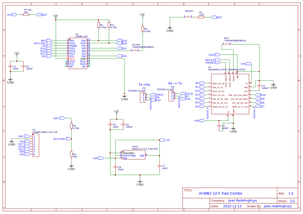
The Schematic and PCB
Software
MQTT Connection on the AI-WB2-12F
The full AT command set example is available here
For the Xiao RP2040, like I used, it is possible to use the second UART to connect to the AI-WB2 chip.
As I am still not completely done with my development, I will not release the full code at this moment.
I have also been informed by AI-Thinker that a new version of the AT-command firmware is available that will allow using the GPIO on the AI-WB2 via AT Commands. I am currently investigating that new version, and that is also a big reason for not releasing any code at this stage.
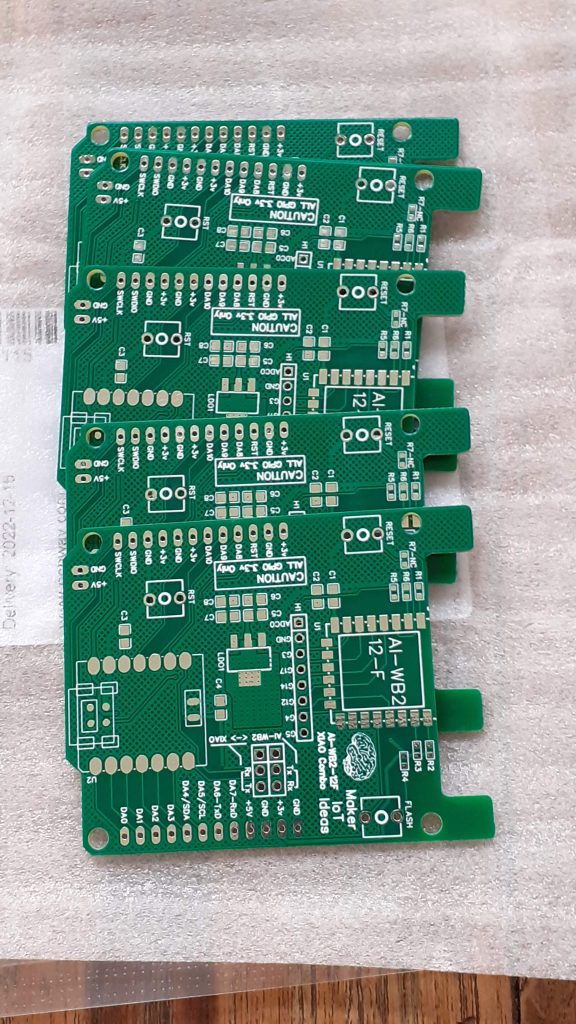
Manufacturing
The PCB for this project has been manufactured at PCBWay.
Please consider supporting them if you would like your own copy of this PCB, or if you have any PCB of your own that you need to have manufactured.

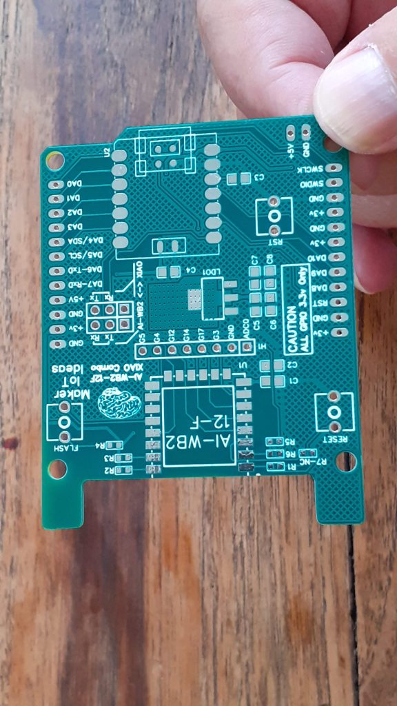
More Pictures


