Xiao RP2040 Joystick Mouse – revision 2.00

Revision 1.0 of the Project


Over the last few months, I have been using the initial revision of this project on almost a daily basis. It has come a long way since the initial concept was implemented on the breadboard.

Initial Concept on a Breadboard

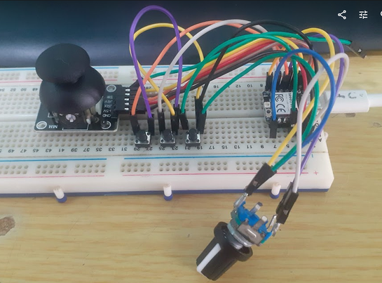
While completely functional, and relatively easy to use, quite a few things started adding up – making me believe that it could be better…

That prompted me to start thinking about a hardware revision, adding some missing features, like a middle button, and “maybe” a display to the device, making it easier to visualise settings, etc…

Current Revision 2.0 ” Proof of concept ” prototype

My main limitations came from the Seeed Studio Xiao RP2040 Module. While super tiny and compact, the module only has access to 11 GPIO pins on the RP2040 chip. Most of these were already in use, connected to buttons etc.

I would thus have to find an I2C IO expander that will be supported by CircuitPython and have a suitably small footprint. That way, I could free up many of the valuable GPIO pins on the Xiao RP2040 for other purposes.

What did I use?

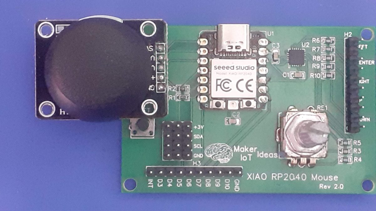
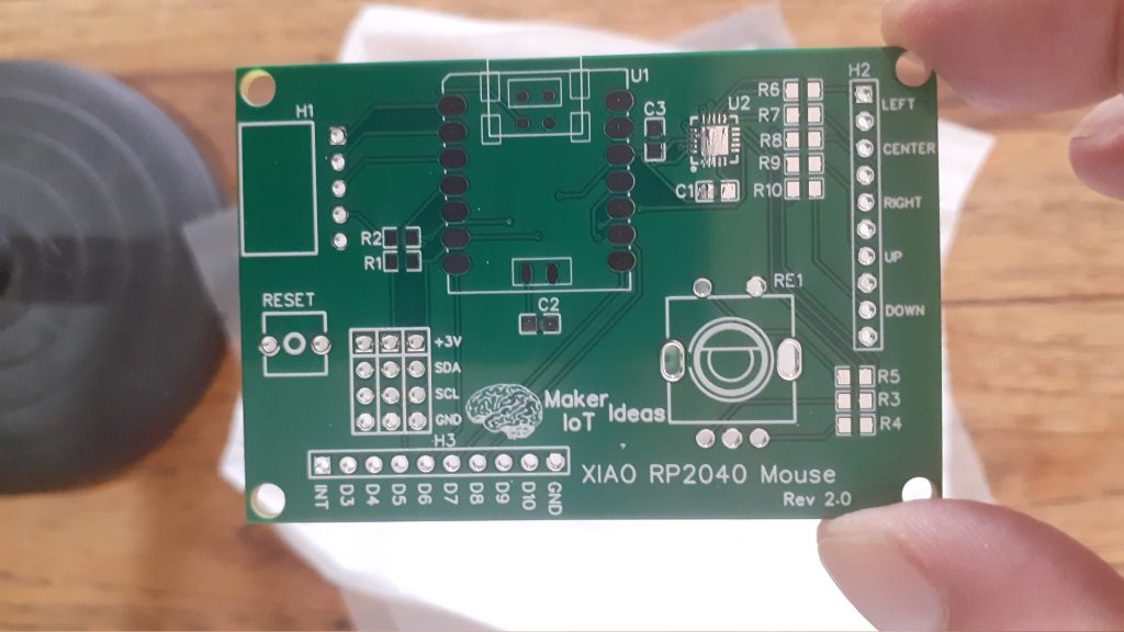
My initial goto chip was the MCP23017, with 16 GPIO pins. But after some more thinking, I settled on the MCP23008, which has only 8 GPIO lines. I2C bus breakout headers to allow for expansion, as well as access to all the unused GPIO pins on the XIAO RP2040, were also added.

The Rotary encoder was once again included, as it could later be used for selecting Menu options etc.

What is the current status of the project?

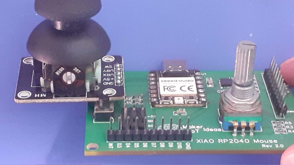
The revision 2.00 hardware works as expected, with a few issues.
CircuitPython has an issue with rotary encoders connected to IO expanders. I don’t understand why that would be the case, but wrote my basic routine to handle the encoder, which at this time, is only used for scrolling. ( I have still got to decide if a display would be needed)

As far as settings are concerned, I have only implemented a sort of “mouse speed” feature that determines how fast or slow ( for better accuracy ) the pointer moves. This is currently controlled by the encoder button, on a cycling loop, with different colours on the NeoPixel as visual feedback on the current speed selected.

USB connectivity at computer startup and/or resuming from a suspend operation is still a major problem. This means that you have to physically reset the device after every resume from suspend, or after starting your computer.
From what I can see in the CircuitPython documentation, it is possible to detect USB connectivity. That part works. From there, It seems that once USB connectivity is lost, CircuitPython goes into some sort of unknown state, and no further code is executed, thus making a software reset not executing…

I have an idea that it has got something to do with the HID Mouse mode or something ???? For now, I am happy to just hit a reset button to continue…

Another big issue is a suitable enclosure. Revision 2.00 PCB was not designed to be placed into an enclosure, mainly because I have so far been quite unsuccessful in finding a suitable one. My 3D design skills are also quite lacking, so designing something from scratch won’t do either. I have decided to sort out all the hardware and firmware issues first, find an enclosure and then modify the PCB layout to fit that.

Manufacturing the PCB

I choose PCBWay for my PCB manufacturing. Why? What makes them different from the rest?

PCBWay‘s business goal is to be the most professional PCB manufacturer for prototyping and low-volume production work in the world. With more than a decade in the business, they are committed to meeting the needs of their customers from different industries in terms of quality, delivery, cost-effectiveness and any other demanding requests. As one of the most experienced PCB manufacturers and SMT Assemblers in China, they pride themselves to be our (the Makers) best business partners, as well as good friends in every aspect of our PCB manufacturing needs. They strive to make our R&D work easy and hassle-free.

How do they do that?

PCBWay is NOT a broker. That means that they do all manufacturing and assembly themselves, cutting out all the middlemen, and saving us money.

PCBWay’s online quoting system gives a very detailed and accurate picture of all costs upfront, including components and assembly costs. This saves a lot of time and hassle.

PCBWay gives you one-on-one customer support, that answers you in 5 minutes ( from the Website chat ), or by email within a few hours ( from your personal account manager). Issues are really resolved very quickly, not that there are many anyway, but, as we are all human, it is nice to know that when a gremlin rears its head, you have someone to talk to who will do his/her best to resolve your issue as soon as possible.

Find out more here

Assembly and Testing

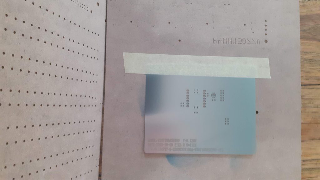
Assembly is easy but does require a stencil due to the small size of some of the SMD components.

CircuitPython Coding – A work in progress

This is the current code, and it is a work in progress. It works, and could definitely be optimised quite a lot. I am not very familiar with Python but I believe I can help myself around it.

import time
import board
import busio
from rainbowio import colorwheel
import neopixel
import digitalio
import rotaryio
import microcontroller
from digitalio import Direction
from adafruit_mcp230xx.mcp23008 import MCP23008
import digitalio
i2c = busio.I2C(board.SCL, board.SDA)
mcp = MCP23008(i2c)

from analogio import AnalogIn
import usb_hid
from adafruit_hid.mouse import Mouse

mouse = Mouse(usb_hid.devices)
xAxis = AnalogIn(board.A2)
yAxis = AnalogIn(board.A1)

# NEOPIXEL
pixel_pin = board.NEOPIXEL
num_pixels = 1
pixels = neopixel.NeoPixel(pixel_pin, num_pixels, brightness=0.1, auto_write=False)

leftbutton = mcp.get_pin(3)
leftbutton.direction = digitalio.Direction.INPUT
leftbutton.pull = digitalio.Pull.UP

centerbutton = mcp.get_pin(4)
centerbutton.direction = digitalio.Direction.INPUT
centerbutton.pull = digitalio.Pull.UP

maint_btn = digitalio.DigitalInOut(board.D0)
maint_btn.switch_to_input(pull=digitalio.Pull.UP)

rightbutton = mcp.get_pin(5)
rightbutton.direction = digitalio.Direction.INPUT
rightbutton.pull = digitalio.Pull.UP

enc_btn = mcp.get_pin(2)
enc_btn.direction = digitalio.Direction.INPUT
enc_btn.pull = digitalio.Pull.UP

scroll_up = mcp.get_pin(6)
scroll_up.direction = digitalio.Direction.INPUT
scroll_up.pull = digitalio.Pull.UP

scroll_down = mcp.get_pin(7)
scroll_down.direction = digitalio.Direction.INPUT
scroll_down.pull = digitalio.Pull.UP

enc_a = mcp.get_pin(0)
enc_a.direction = digitalio.Direction.INPUT
enc_a.pull = digitalio.Pull.UP

enc_b = mcp.get_pin(1)
enc_b.direction = digitalio.Direction.INPUT
enc_b.pull = digitalio.Pull.UP

enc_a_pressed = False
enc_b_pressed = False

#mousewheel = rotaryio.IncrementalEncoder(enc_a, mcp.get_pin(1))
#last_position = mousewheel.position

move_speed = 3
enc_down = 0

RED = (255, 0, 0)
YELLOW = (255, 150, 0)
GREEN = (0, 255, 0)
CYAN = (0, 255, 255)
BLUE = (0, 0, 255)
PURPLE = (180, 0, 255)
BLACK = (0, 0, 0)


if move_speed == 0:
    in_min, in_max, out_min, out_max = (0, 65000, -20, 20)
    filter_joystick_deadzone = (
        lambda x: int((x - in_min) * (out_max - out_min) / (in_max - in_min) + out_min)
        if abs(x - 32768) > 500
        else 0
    )
if move_speed == 1:
    pixels.fill(GREEN)
    pixels.show()
    in_min, in_max, out_min, out_max = (0, 65000, -15, 15)
    filter_joystick_deadzone = (
        lambda x: int((x - in_min) * (out_max - out_min) / (in_max - in_min) + out_min)
        if abs(x - 32768) > 500
        else 0
    )
if move_speed == 2:
    pixels.fill(BLUE)
    pixels.show()
    in_min, in_max, out_min, out_max = (0, 65000, -10, 10)


filter_joystick_deadzone = (
        lambda x: int((x - in_min) * (out_max - out_min) / (in_max - in_min) + out_min)
        if abs(x - 32768) > 500
        else 0
    )
if move_speed == 3:
    pixels.fill(PURPLE)
    pixels.show()
    in_min, in_max, out_min, out_max = (0, 65000, -8, 8)
    filter_joystick_deadzone = (
        lambda x: int((x - in_min) * (out_max - out_min) / (in_max - in_min) + out_min)
        if abs(x - 32768) > 500
        else 0
    )
if move_speed == 4:
    pixels.fill(CYAN)
    pixels.show()
    in_min, in_max, out_min, out_max = (0, 65000, -5, 5)
    filter_joystick_deadzone = (
        lambda x: int((x - in_min) * (out_max - out_min) / (in_max - in_min) + out_min)
        if abs(x - 32768) > 500
        else 0
    )


pixels.fill(BLACK)
pixels.show()
while True:
    # Set mouse accelleration ( speed)
    if move_speed == 0:
        pixels.fill(BLACK)
        pixels.show()
        in_min, in_max, out_min, out_max = (0, 65000, -20, 20)
        filter_joystick_deadzone = (
            lambda x: int(
                (x - in_min) * (out_max - out_min) / (in_max - in_min) + out_min
            )
            if abs(x - 32768) > 500
            else 0
        )
    if move_speed == 1:
        pixels.fill(GREEN)
        pixels.show()
        in_min, in_max, out_min, out_max = (0, 65000, -15, 15)
        filter_joystick_deadzone = (
            lambda x: int(
                (x - in_min) * (out_max - out_min) / (in_max - in_min) + out_min
            )
            if abs(x - 32768) > 500
            else 0
        )
    if move_speed == 2:
        pixels.fill(BLUE)
        pixels.show()
        in_min, in_max, out_min, out_max = (0, 65000, -10, 10)
        filter_joystick_deadzone = (
            lambda x: int(
                (x - in_min) * (out_max - out_min) / (in_max - in_min) + out_min
            )
            if abs(x - 32768) > 500
            else 0
        )
    if move_speed == 3:
        pixels.fill(PURPLE)
        pixels.show()
        in_min, in_max, out_min, out_max = (0, 65000, -8, 8)
        filter_joystick_deadzone = (
            lambda x: int(
                (x - in_min) * (out_max - out_min) / (in_max - in_min) + out_min
            )
            if abs(x - 32768) > 500
            else 0
        )
    if move_speed == 4:
        pixels.fill(CYAN)
        pixels.show()
        in_min, in_max, out_min, out_max = (0, 65000, -5, 5)
        filter_joystick_deadzone = (
            lambda x: int(
                (x - in_min) * (out_max - out_min) / (in_max - in_min) + out_min
            )
            if abs(x - 32768) > 500
            else 0
        )

    #current_position = mousewheel.position
    #position_change = current_position - last_position

    x_offset = filter_joystick_deadzone(xAxis.value) * -1  # Invert axis
    y_offset = filter_joystick_deadzone(yAxis.value) * -1
    mouse.move(x_offset, y_offset, 0)

    if enc_btn.value and enc_down == 1:
        move_speed = move_speed + 1
        if move_speed > 4:
            move_speed = 0

        # print (move_speed)
        enc_down = 0

    if not enc_btn.value:
        enc_down = 1

    if leftbutton.value:
        mouse.release(Mouse.LEFT_BUTTON)
        # pixels.fill(BLACK)
        # pixels.show()
    else:
        mouse.press(Mouse.LEFT_BUTTON)
        pixels.fill(GREEN)
        pixels.show()

    if centerbutton.value:
        mouse.release(Mouse.MIDDLE_BUTTON)
    else:
        mouse.press(Mouse.MIDDLE_BUTTON)
        pixels.fill(YELLOW)
        pixels.show()

    # Center button on joystick
    if maint_btn.value:
        mouse.release(Mouse.LEFT_BUTTON)
    else:
        mouse.press(Mouse.LEFT_BUTTON)
        pixels.fill(GREEN)
        pixels.show()

    if rightbutton.value:
        mouse.release(Mouse.RIGHT_BUTTON)
        # pixels.fill(BLACK)
        # pixels.show()
    else:
        mouse.press(Mouse.RIGHT_BUTTON)
        pixels.fill(PURPLE)
        pixels.show()

    if not scroll_up.value:
        mouse.move(wheel=1)
        time.sleep(0.25)
        pixels.fill(BLUE)
        pixels.show()

    if not scroll_down.value:
        mouse.move(wheel=-1)
        time.sleep(0.25)
        pixels.fill(CYAN)
        pixels.show()

    if not scroll_up.value and not scroll_down.value:
        for x in range(4):
            pixels.fill(RED)
            pixels.show()
            time.sleep(0.5)
            pixels.fill(BLACK)
            pixels.show()
            time.sleep(0.5)
        microcontroller.reset()

    if enc_a.value:
        enc_a_pressed = False
    else:
        if enc_b_pressed:
            enc_a_pressed = False
        else:
            enc_a_pressed = True

    if enc_b.value:
        enc_b_pressed = False
    else:
        if enc_a_pressed:
            enc_b_pressed = False
        else:
            enc_b_pressed = True

    if enc_a_pressed:
        mouse.move(wheel=1)
        time.sleep(0.25)
        enc_a_pressed = False
    if enc_b_pressed:
        mouse.move(wheel=-1)
        time.sleep(0.25)
        enc_b_pressed = False

    #if position_change > 0:
    #    mouse.move(wheel=position_change)
    #    # print(current_position)
    #    pixels.fill(BLUE)
    #    pixels.show()
    #elif position_change < 0:
    #    mouse.move(wheel=position_change)
    #    # print(current_position)
    #    pixels.fill(CYAN)
    #    pixels.show()
    #last_position = current_position
    pixels.fill(BLACK)
    pixels.show()

Conclusion

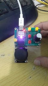
Okay, so this is where it is at at the moment. The code is not perfect, and the hardware is not perfect, but it works. I am using this device every day, and also making changes as needed. At the moment, there are some issues, but they do not prevent the actual use of the device.

If you are interested or would like to make modifications, feel free to do so.

Simplifying Robotics with Raspberry Pi® RP2040

Introducing the Cytron Maker RP2040

Cytron Maker Pi RP2040 features the first microcontroller designed by Raspberry Pi – RP2040, embedded on a robot controller board. This board comes with a dual-channel DC motor driver, 4 servo motor ports and 7 Grove I/O connectors, ready for your next DIY robot/motion control project. Now you can build a robot while trying out the new RP2040 chip.


The DC motor driver on board is able to control 2x brushed DC motors or 1x bipolar/unipolar stepper motor rated from 3.6V to 6V, providing up to 1A current per channel continuously. The built-in Quick Test buttons and motor output LEDs allow a functional test of the motor driver in a quick and convenient way, without the need of writing any code. Vmotor for both DC and servo motors depends on the input voltage supplied to the board.


Credit: 3D robot parts designed by Camilo Parra Palacio from OttoDIY Community.


Credit: Self-watering Planter 3D parts on Thingiverse.
 

Maker Pi RP2040 features all the goodness of Cytron’s Maker series products. It too has lots of LEDs useful for troubleshooting (& visual effects), is able to make quite some noise with the onboard piezo buzzer and comes with push buttons ready to detect your touch.

There are three ways to supply power to the Maker Pi RP2040 – via USB (5V) socket, with a single cell LiPo/Li-Ion battery or through the VIN (3.6-6V) terminals. However, only one power source is needed to power up both controller board and motors at a time. Power supply from all these power sources can all be controlled with the power on/off switch onboard.

Cytron Maker Pi RP2040 is basically the Raspberry Pi Pico + Maker series’ goodness + Robot controller & other useful features. Therefore this board is compatible with the existing Pico ecosystem. Software, firmware, libraries and resources that are developed for Pico should work seamlessly with Cytron Maker Pi RP2040 too.

CircuitPython is preloaded on the Maker Pi RP2040 and it runs a simple demo program right out of the box. Connect it to your computer via USB micro cable and turn it on, you will be greeted by a melody tune and LEDs running light. Press GP20 and GP21 push buttons to toggle the LEDs on/off while controlling any DC and servo motors connected to it to move and stop. With this demo code, you get to test the board the moment you receive it!

While connected to your computer, a new CIRCUITPY drive appears. Explore and edit the demo code (code.py & lib folder) with any code editor you like, save any changes to the drive and you shall see it in action in no time. That’s why we embrace CircuitPython – it’s very easy to get started. Wish to use other programming languages? Sure, you are free to use MicroPython and C/C++ for Pico/RP2040. For those of you who love the Arduino ecosystem, please take a look at this official news by Arduino and also the unofficial Pico Arduino Core by Earle F. Philhower.

Features:

  • Powered by Rapberry Pi RP2040
    • Dual-core Arm Cortex-M0+ processor
    • 264KB internal RAM
    • 2MB of Flash memory
    • the exact same specifications with Raspberry Pi Pico
  • Robot controller board
    • 4x Servo motors
    • 2x DC motors with quick test buttons
  • Versatile power circuit
    • Automatic power selection: USB 5V, LiPo (1-cell) or Vin (3.6-6V)
    • Built-in 1-cell LiPo/Li-Ion charger (over-charged & over-discharged protection)
    • Power on/off switch
  • 13x Status indicator LEDs for GPIO pins
  • 1x Piezo buzzer with mute switch
  • 2x Push button
  • 2x RGB LED (Neopixel)
  • 7x Grove ports (flexible I/O options: digital, analog, I2C, SPI, UART…)
  • Preloaded with CircuitPython by default
  • Mouting holes
    • 4x 4.8mm mounting hole (LEGO® pin compatible)
    • 6x M3 screw hole

Maker Pi RP2040 VS. Maker Pi Pico?


Board Layout:

Dimension:

88mm(L) x 64mm(W) x 13mm(H)

Packing List:

Resources:

Introducing Maker Pi RP2040

Cytron Technologies has done it again, this time by releasing an in-house designed complete robotics controller board, based on the brand new RP2040 MCU from the Raspberry Pi Foundation.

This post will be part one of a detailed look at this new product.. So, as it is an introduction, lets get some technical specs and features…

Features:

  • Powered by Rapberry Pi RP2040
    • Dual-core Arm Cortex-M0+ processor
    • 264KB internal RAM
    • 2MB of Flash memory
    • the exact same specifications with Raspberry Pi Pico
  • Robot controller board
    • 4x Servo motors
    • 2x DC motors with quick test buttons
  • Versatile power circuit
    • Automatic power selection: USB 5V, LiPo (1-cell) or Vin (3.6-6V)
    • Built-in 1-cell LiPo/Li-Ion charger (over-charged & over-discharged protection)
    • Power on/off switch
  • 13x Status indicator LEDs for GPIO pins
  • 1x Piezo buzzer with mute switch
  • 2x Push button
  • 2x RGB LED (Neopixel)
  • 7x Grove ports (flexible I/O options: digital, analog, I2C, SPI, UART…)
  • Preloaded with CircuitPython by default
  • Mouting holes
    • 4x 4.8mm mounting hole (LEGO® pin compatible)
    • 6x M3 screw hole


Cytron Maker Pi RP2040 features the first micro-controller designed by Raspberry Pi – RP2040, embedded on a robot controller board. The board also comes with dual channel DC motor driver, 4 servo motor ports and 7 Grove I/O connectors, ready for your next DIY robot / motion control project. Now you can build robot, while trying out the new RP2040 chip.

The DC motor driver onboard is able to control 2x brushed DC motors or 1x bipolar/unipolar stepper motor rated from 3.6V to 6V, providing up to 1A current per channel continuously. The built-in Quick Test buttons and motor output LEDs allow functional test of the motor driver in a quick and convenient way, without the need of writing any code. Vmotor for both DC and servo motors depends on the input voltage supplied to the board.

ker Pi RP2040 features all the goodness of Cytron’s Maker series products. It too has lots of LEDs useful for troubleshooting (& visual effects), is able to make quite some noise with the onboard piezo buzzer and comes with push buttons ready to detect your touch.

There are three ways to supply power to the Maker Pi RP2040 – via USB (5V) socket, with a single cell LiPo/Li-Ion battery or through the VIN (3.6-6V) terminals. However only one power source is needed to power up both controller board and motors at a time. Power supply from all these power sources can all be controlled with the power on/off switch onboard.

Cytron Maker Pi RP2040 is basically the Raspberry Pi Pico + Maker series’ goodness + Robot controller & other useful features. Therefore this board is compatible with the existing Pico ecosystem. Software, firmware, libraries and resources that are developed for Pico should work seamlessly with Cytron Maker Pi RP2040 too.

CircuitPython is preloaded on the Maker Pi RP2040 and it runs a simple demo program right out-of-the-box. Connect it to your computer via USB micro cable and turn it on, you will be greeted by a melody tune and LEDs running light. Press GP20 and GP21 push buttons to toggle the LEDs on/off, while controlling any DC and servo motors connected to it to move and stop. With this demo code, you get to test the board the moment you receive it!


 Out-of-the-box Demo for Cytron Maker Pi RP2040
  
 This demo code is written in CircuitPython and it serves
 as an easy quality check when you first receive the board.
 #
 It plays a melody upon power up (slide power switch to ON)
 and shows running lights (blue LEDs) at the same time.
 Then the two RGB LEDs will animate the colors, while the
 program checking push buttons' state, repeatedly.
  
 Press GP20 button to play a short melody, lights up all
 blue LEDs, move servo motors to 0 degree and run DC motors
 at 50% and -50% speeds.
 Press GP21 button to play another melody, turn off all blue
 LEDs, move servo motors to 180 degree & brake DC motors.
  
 Maker Pi RP2040 also has four DC motors quick test buttons
 built-in. You may press the onboard M1A, M1B, M2A or M2B
 push buttons to run your motors without writing any code.
 #
 More info:
 http://www.cytron.io/p-maker-pi-rp2040
 https://circuitpython.org/board/raspberry_pi_pico
 #
 Email: support@cytron.io
 *
 import board
 import digitalio
 import neopixel
 import simpleio
 import time
 import pwmio
 from adafruit_motor import servo, motor
 Initialize LEDs
 LEDs placement on Maker Pi RP2040
 LED_PINS = [board.GP0, 
             board.GP1,
             board.GP2,
             board.GP3,
             board.GP4,
             board.GP5,
             board.GP6,
             board.GP7,
             board.GP16,
             board.GP17,
             board.GP26,
             board.GP27,
             board.GP28]
 LEDS = []
 for pin in LED_PINS:
     # Set pins as digital output
     digout = digitalio.DigitalInOut(pin)
     digout.direction = digitalio.Direction.OUTPUT
     LEDS.append(digout)
 Initialize Neopixel RGB LEDs
 pixels = neopixel.NeoPixel(board.GP18, 2)
 pixels.fill(0)
 Melody
 MELODY_NOTE = [659, 659, 0, 659, 0, 523, 659, 0, 784]
 MELODY_DURATION = [0.15, 0.15, 0.15, 0.15, 0.15, 0.15, 0.15, 0.15, 0.2]
 Define pin connected to piezo buzzer
 PIEZO_PIN = board.GP22
 Initialize buttons
 btn1 = digitalio.DigitalInOut(board.GP20)
 btn2 = digitalio.DigitalInOut(board.GP21)
 btn1.direction = digitalio.Direction.INPUT
 btn2.direction = digitalio.Direction.INPUT
 btn1.pull = digitalio.Pull.UP
 btn2.pull = digitalio.Pull.UP
 Initialize servos
 50% duty cycle: 2**15 = 32768 = 1/2 of 65536 (16-bit)
 servo_motors = []  # create an array and add servo objects.
 servo_motors.append(servo.Servo(pwmio.PWMOut(board.GP12, duty_cycle=215, frequency=50))) servo_motors.append(servo.Servo(pwmio.PWMOut(board.GP13, duty_cycle=215, frequency=50)))
 servo_motors.append(servo.Servo(pwmio.PWMOut(board.GP14, duty_cycle=215, frequency=50))) servo_motors.append(servo.Servo(pwmio.PWMOut(board.GP15, duty_cycle=215, frequency=50)))
 Initialize DC motors
 m1a = pwmio.PWMOut(board.GP8, frequency=50)
 m1b = pwmio.PWMOut(board.GP9, frequency=50)
 motor1 = motor.DCMotor(m1a, m1b)
 m2a = pwmio.PWMOut(board.GP10, frequency=50)
 m2b = pwmio.PWMOut(board.GP11, frequency=50)
 motor2 = motor.DCMotor(m2a, m2b)
 -------------------------------------------------
 ON START: Show running light and play melody
 -------------------------------------------------
 for i in range(len(LEDS)):
     LEDS[i].value = True
 if i < len(MELODY_NOTE):     # Play melody tones     simpleio.tone(PIEZO_PIN, MELODY_NOTE[i], duration=MELODY_DURATION[i]) else:     # Light up the remainding LEDs     time.sleep(0.15)
 Turn off LEDs one-by-one very quickly
 for i in range(len(LEDS)):
     LEDS[i].value = False
     time.sleep(0.02)
 color = 0
 state = 0
 -------------------------------------------------
 FOREVER LOOP: Check buttons & animate RGB LEDs
 -------------------------------------------------
 while True:
 # Check button 1 (GP20) if not btn1.value:  # button 1 pressed     # Light up all LEDs     for i in range(len(LEDS)):         LEDS[i].value = True     # Move servos to 0 degree     for i in range(len(servo_motors)):         servo_motors[i].angle = 0     # Move motors at 50% speed     motor1.throttle = 0.5  # motor1.throttle = 1 or -1 for full speed     motor2.throttle = -0.5     # Play tones     simpleio.tone(PIEZO_PIN, 262, duration=0.1)     simpleio.tone(PIEZO_PIN, 659, duration=0.15)     simpleio.tone(PIEZO_PIN, 784, duration=0.2) # Check button 2 (GP21) elif not btn2.value:  # button 2 pressed     # Turn off all LEDs     for i in range(len(LEDS)):         LEDS[i].value = False     # Move servos to 180 degree     for i in range(len(servo_motors)):         servo_motors[i].angle = 180     # Brake motors     motor1.throttle = 0  # motor1.throttle = None to spin freely     motor2.throttle = 0     # Play tones     simpleio.tone(PIEZO_PIN, 784, duration=0.1)     simpleio.tone(PIEZO_PIN, 659, duration=0.15)     simpleio.tone(PIEZO_PIN, 262, duration=0.2) # Animate RGB LEDs if state == 0:     if color < 0x101010:         color += 0x010101   # increase rgb colors to 0x10 each     else:         state += 1 elif state == 1:     if (color & 0x00FF00) > 0:         color -= 0x000100   # decrease green to zero     else:         state += 1 elif state == 2:     if (color & 0xFF0000) > 0:         color -= 0x010000   # decrease red to zero     else:         state += 1 elif state == 3:     if (color & 0x00FF00) < 0x1000:         color += 0x000100   # increase green to 0x10     else:         state += 1 elif state == 4:     if (color & 0x0000FF) > 0:         color -= 1          # decrease blue to zero     else:         state += 1 elif state == 5:     if (color & 0xFF0000) < 0x100000:         color += 0x010000   # increase red to 0x10     else:         state += 1 elif state == 6:     if (color & 0x00FF00) > 0:         color -= 0x000100   # decrease green to zero     else:         state += 1 elif state == 7:     if (color & 0x00FFFF) < 0x001010:         color += 0x000101   # increase gb to 0x10     else:         state = 1 pixels.fill(color)  # fill the color on both RGB LEDs # Sleep to debounce buttons & change the speed of RGB color swipe time.sleep(0.05)

Maker Pi RP2040 VS. Maker Pi Pico?