As a follow-up on the ESP-12E Card, today we will look at the prototype base card that this was designed to slot into – The ESP-12E I2c Base Card.
Initial Features ( To be expanded in future versions )
4 x 40Pin Expansion slots, with access to 12v, 3.3v and Gnd on each slot. 2 x “IRQ” pins per slot ( serviced by a single PCF8574 ) I2C bus access on each slot (3.3v ) UART Header Reset and Flash Header GPIO Header ( Direct access to the ESP-12E GPIO Pins ) Analog Input Header (a Single input – A0, as per ESP-12E limitation) Buck Converter Power Supply Module, capable of up to 2A of current
Over the past eight years, PCBWay has continuously upgraded their MANUFACTURING plants and equipment to meet higher quality requirements, and now THEY also provide OEM services to build your products from ideas to mass production and access to the market.
The PCB for this project has been manufactured at PCBWay. Please consider supporting them if you would like your own copy of this PCB, or if you have any PCB of your own that you need to have manufactured.
If you would like to have PCBWAY manufacture one of your own, designs, or even this particular PCB, you need to do the following… 1) Click on this link 2) Create an account if you have not already got one of your own. If you use the link above, you will also instantly receive a $5 USD coupon, which you can use on your first or any other order later. (Disclaimer: I will earn a small referral fee from PCBWay. This referral fee will not affect the cost of your order, nor will you pay any part thereof.) 3) Once you have gone to their website, and created an account, or login with your existing account,
4) Click on PCB Instant Quote
5) If you do not have any very special requirements for your PCB, click on Quick-order PCB
6) Click on Add Gerber File, and select your Gerber file(s) from your computer. Most of your PCB details will now be automatically selected, leaving you to only select the solder mask and silk-screen colour, as well as to remove the order number or not. You can of course fine-tune everything exactly as you want as well.
7) You can also select whether you want an SMD stencil, or have the board assembled after manufacturing. Please note that the assembly service, as well as the cost of your components, ARE NOT included in the initial quoted price. ( The quote will update depending on what options you select ).
8) When you are happy with the options that you have selected, you can click on the Save to Cart Button. From here on, you can go to the top of the screen, click on Cart, make any payment(s) or use any coupons that you have in your account.
Then just sit back and wait for your new PCB to be delivered to your door via the shipping company that you have selected during checkout.
A few months ago, I started working on an MCU Card design, which borrows from the idea of a standard desktop PC, in which there are a main-board, MCU and expansion slots, to add and remove peripherals as needed quickly.
The ESP-12E Card is a continuation of that project, with the ultimate goal to have a universal “main-board” that can accept various MCUs and standardised “expansion modules” that perform a specific task.
ESP-12E Card
The PCB
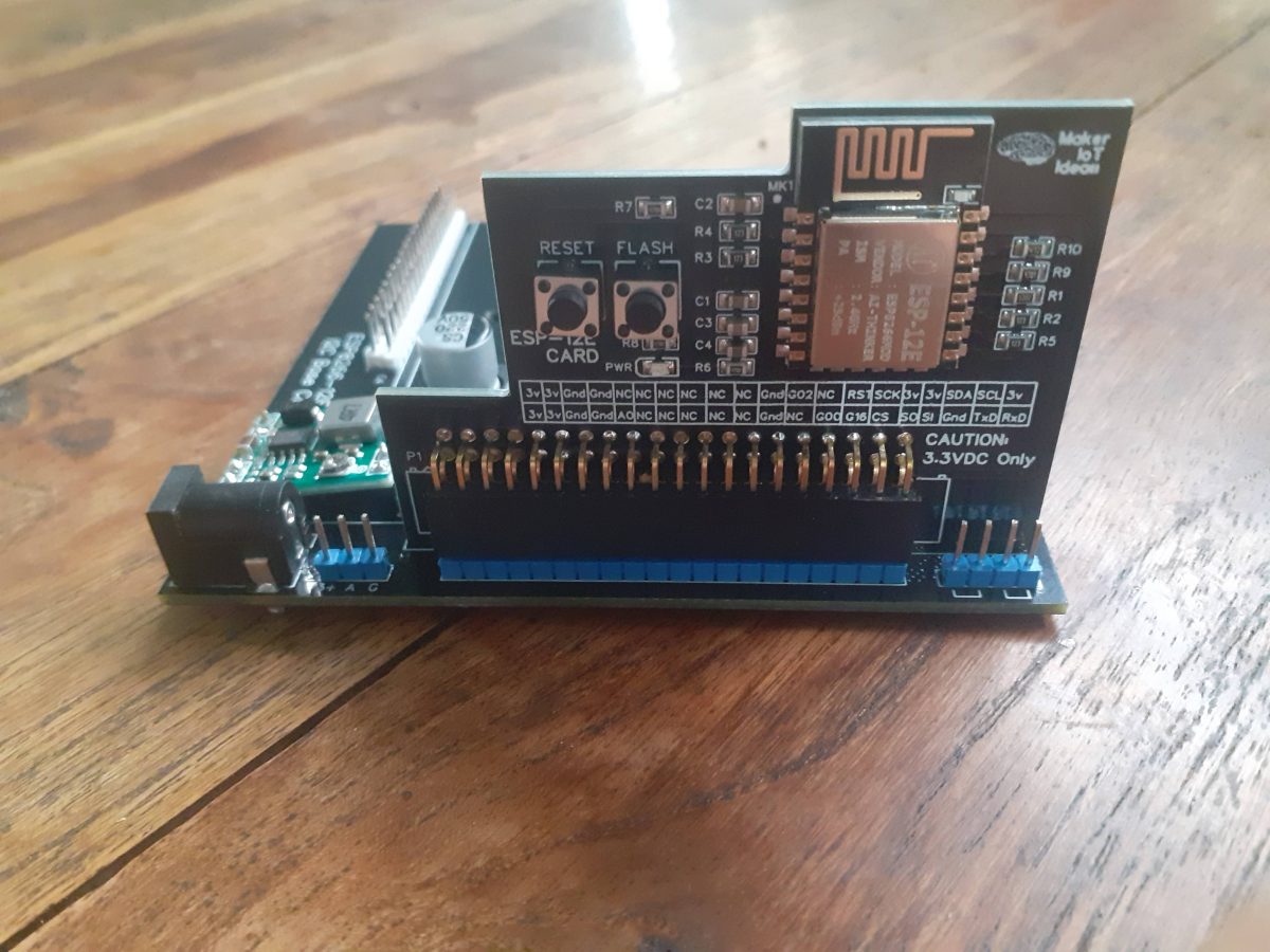
The ESP-12E Card contains the bare minimum components to allow the chip to function. There are no power regulators or USB-to-TTL converters onboard. Code is flashed via an external USB-to-TTL converter, with Flash and Reset buttons on the actual PCB, or available in the 2×20 Pin female header at the bottom of the card.
Most of the GPIO is also broken out to the 2×20 pin header, with the exception of the 6 GPIO that is usually connected to the internal Flash on the ESP-12E module.
I have made provision for enough power and ground pins on the header as well.
As far as GPIO is concerned, They have been grouped together by function, as much as possible at least, to make interfacing with the base-board as easy as possible.
The Schematic
ESP-12E Card Schematic
The schematic is not complicated. It is a standard ESP-8266 configuration, with all non-essential components removed.
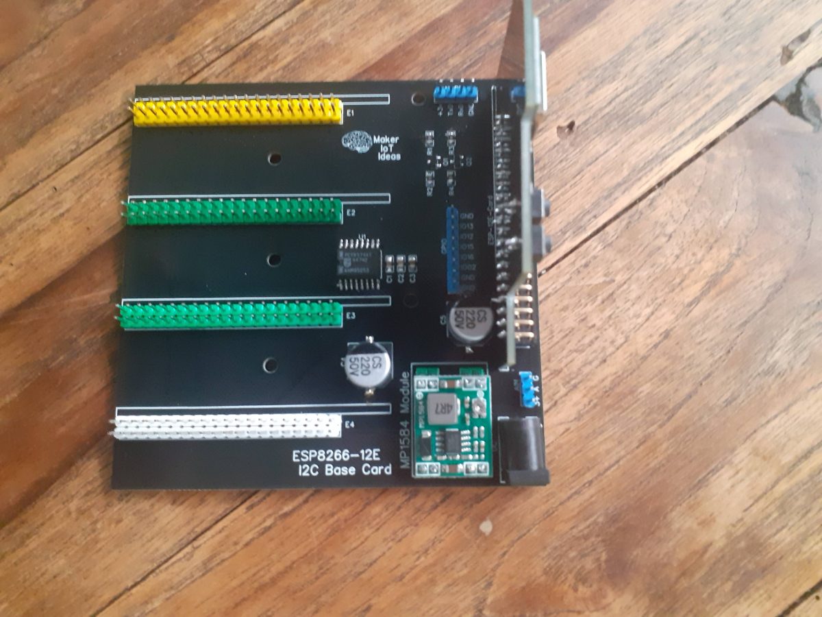
The “base-board” ( a sneak preview )
Sneak preview of the Base Card
In a future article, I will tell you more about this ( for the time being limited to I2C ) base card. [ a quick explanation: When I mean limited to I2C, it relates to the fact that at the moment, the base card, ( a prototype ) can only communicate back to the MCU via I2C protocol from each of the expansion slots, as well as via two dedicated IRQ lines from each slot ]Power is supplied via a small SMPS module.
Manufacturing the PCB
Over the past eight years, PCBWay has continuously upgraded their MANUFACTURING plants and equipment to meet higher quality requirements, and now THEY also provide OEM services to build your products from ideas to mass production and access to the market.
The PCB for this project has been manufactured at PCBWay. Please consider supporting them if you would like your own copy of this PCB, or if you have any PCB of your own that you need to have manufactured.
If you would like to have PCBWAY manufacture one of your own, designs, or even this particular PCB, you need to do the following… 1) Click on this link 2) Create an account if you have not already got one of your own. If you use the link above, you will also instantly receive a $5 USD coupon, which you can use on your first or any other order later. (Disclaimer: I will earn a small referral fee from PCBWay. This referral fee will not affect the cost of your order, nor will you pay any part thereof.) 3) Once you have gone to their website, and created an account, or login with your existing account,
4) Click on PCB Instant Quote
5) If you do not have any very special requirements for your PCB, click on Quick-order PCB
6) Click on Add Gerber File, and select your Gerber file(s) from your computer. Most of your PCB details will now be automatically selected, leaving you to only select the solder mask and silk-screen colour, as well as to remove the order number or not. You can of course fine-tune everything exactly as you want as well.
7) You can also select whether you want an SMD stencil, or have the board assembled after manufacturing. Please note that the assembly service, as well as the cost of your components, ARE NOT included in the initial quoted price. ( The quote will update depending on what options you select ).
8) When you are happy with the options that you have selected, you can click on the Save to Cart Button. From here on, you can go to the top of the screen, click on Cart, make any payment(s) or use any coupons that you have in your account.
Then just sit back and wait for your new PCB to be delivered to your door via the shipping company that you have selected during checkout.
Today we will look at the remote control unit for the Robotic Toy Car – Part 6. The project is close to being completed, and as such, there are quite a lot of final things that need to be taken care of.
One of these will definitely be the final coding, which I will release in the final part of the project, so with that in mind, let us take a look at the remote control unit.
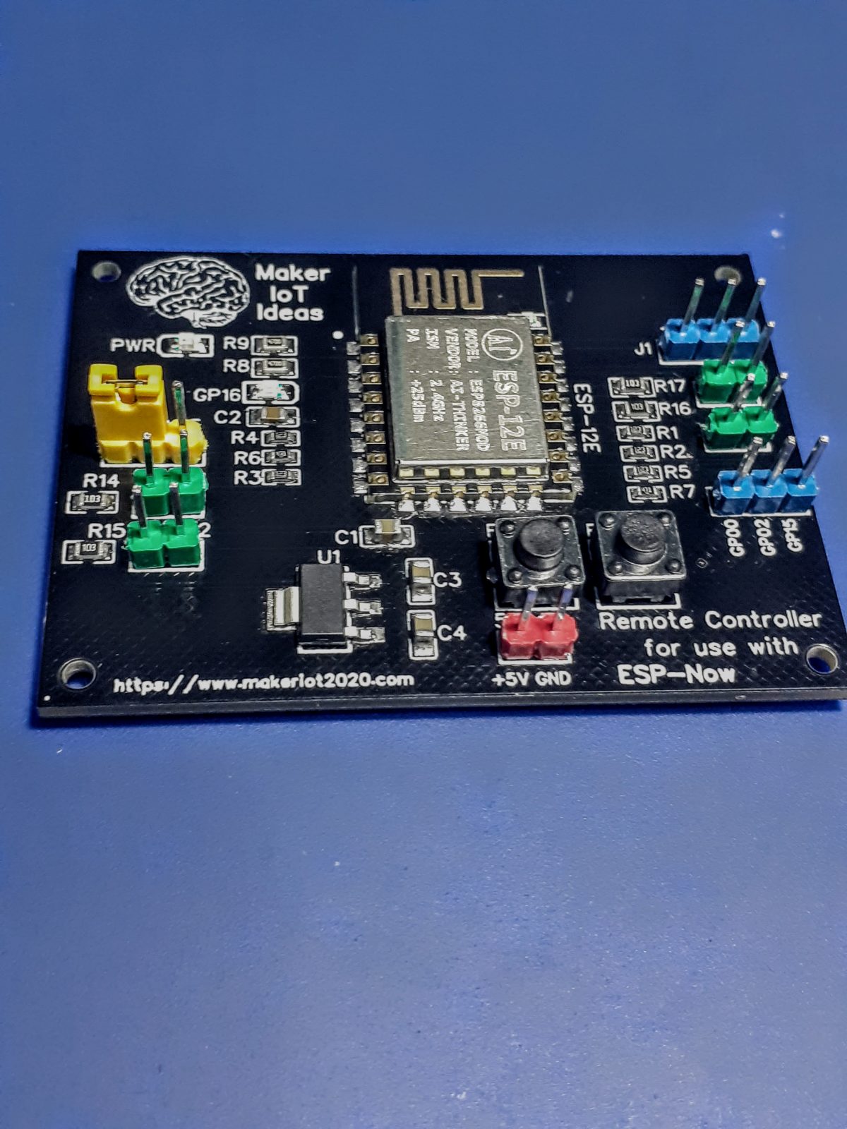
Remote Control Unit, designed to be used with ESP-Now
I have decided to do something completely different from standard remote control units, being that I will use ESP-Now, a protocol developed by Espressif. ESP-Now runs on the Wifi hardware of the ESP8266 or ESP32 and is basically a peer-to-peer protocol, that does not require Wifi but can co-exist with it on the same device. Outdoors, ESP-Now has a range of about 100m, which should work very well for my intended use.
The Remote control, as designed, will have 4 dedicated buttons: forward, reverse, left and right, divided into two groups to make two-handed control easier, similar to a standard game controller. No input on either of the two groups will result in stopping the vehicle, in the case of forwards and backwards, and centring the steering, in the case of the left-right axis.
a 3D Rendered Image of the PCB, motion axis on SW1 and SW2, steering axis on SW3 and SW4
As I always try to make my designs somewhat reusable for other purposes, I have also broken out most of the unused GPIO pins to header pins, with also adding a jumper on GPIO16 to make deep-sleep wakeup mode possible., You can also re-use the switch pins for other purposes, just remember to first remove the 10k pull-up resistors at R14, R15, R16, and R17…
GPIO16 can be reused as well, just remove the jumper, but remember that it is pulled up through a LED and a 470ohm resistor…
There is no USB-to-serial converter onboard, I have been having quite a lot of headaches with them over the last few months, with almost all CH340G chips that I have purchased, being fake, or dead-on arrivals that don’t work… Sending them back to the suppliers, unfortunately, results in unpleasantries, because even placing them in verified working circuits, still proves them to be not working… This is however not an issue, as it is quite easy to upload the board with an external adapter.
The Schematic
Schematic Diagram
Manufacturing the PCB
Over the past eight years, PCBWay has continuously upgraded their MANUFACTURING plants and equipment to meet higher quality requirements, and now THEY also provide OEM services to build your products from ideas to mass production and access to the market.
The PCB for this project has been manufactured at PCBWay. Please consider supporting them if you would like your own copy of this PCB, or if you have any PCB of your own that you need to have manufactured.
If you would like to have PCBWAY manufacture one of your own, designs, or even this particular PCB, you need to do the following… 1) Click on this link 2) Create an account if you have not already got one of your own. If you use the link above, you will also instantly receive a $5USD coupon, which you can use on your first or any other order later. (Disclaimer: I will earn a small referral fee from PCBWay. This referral fee will not affect the cost of your order, nor will you pay any part thereof.) 3) Once you have gone to their website, and created an account, or login with your existing account,
4) Click on PCB Instant Quote
5) If you do not have any very special requirements for your PCB, click on Quick-order PCB
6) Click on Add Gerber File, and select your Gerber file(s) from your computer. Most of your PCB details will now be automatically selected, leaving you to only select the solder mask and silk-screen colour, as well as to remove the order number or not. You can of course fine-tune everything exactly as you want as well.
7) You can also select whether you want an SMD stencil, or have the board assembled after manufacturing. Please note that the assembly service, as well as the cost of your components, ARE NOT included in the initial quoted price. ( The quote will update depending on what options you select ).
8) When you are happy with the options that you have selected, you can click on the Save to Cart Button. From here on, you can go to the top of the screen, click on Cart, make any payment(s) or use any coupons that you have in your account.
Then just sit back and wait for your new PCB to be delivered to your door via the shipping company that you have selected during checkout.
In this part of the series, Robotic Toy Car – Part 4, We will add some custom side-panels to the project. While the original toy did come with some laser cut aluminum side panels, I decided to replace them with PCB versions, with even more flashing lights (yes, this thing is turning into a “Christmas tree” , but that is what the eventual owner wanted… )
These side-panels will not be programmable. They will simply be operated from a standard 555 timer and a couple of other components, to give a flash time of about one second on and off each…
It is also an excellent project to showcase the capabilities of PCBWay, in dealing with a “rather difficult” PCB to manufacture. As you may know by now, I use PCBWay‘s services quite extensively, and I also only design my PCB’s with EasyEDA. EasyEDA is however quite limited in some aspects, and as far as myself, making panels of different designs on one PCB with complex shapes is not something that I do every day…
Let us take a look at what had to be done, and how well it was manufactured…
The PCB Layout
What we have here, is basically two mirrored side-panels ( as far as the visible “outside” is concerned anyway ) That consists of 6 led’s per side that will flash alternatively. On the “inside” we have a 555 timer chip, with some resistors and capacitors, as well as transistors that does the switching.
The Schematic
The difficulty of this PCB is definitely in the manufacturing. I was however pleasantly surprised with the excellent work that was done by PCBWay. Their Engineering staff did contact me early on in the order, with a suggested plan to manufacture, and once I approved that, they very quickly went on to production. My initial concern was that they suggested “mouse-bites” which we all know can sometimes come out a bit strange…
Completed PCB in packaging..
I was however extremely pleased when the above parcel arrived… They added side rails, and the “mouse-bytes” were super tiny.
After assembly ( not cleaned up yet )After Assembly ( not cleaned up yet )Installed on the toy car body
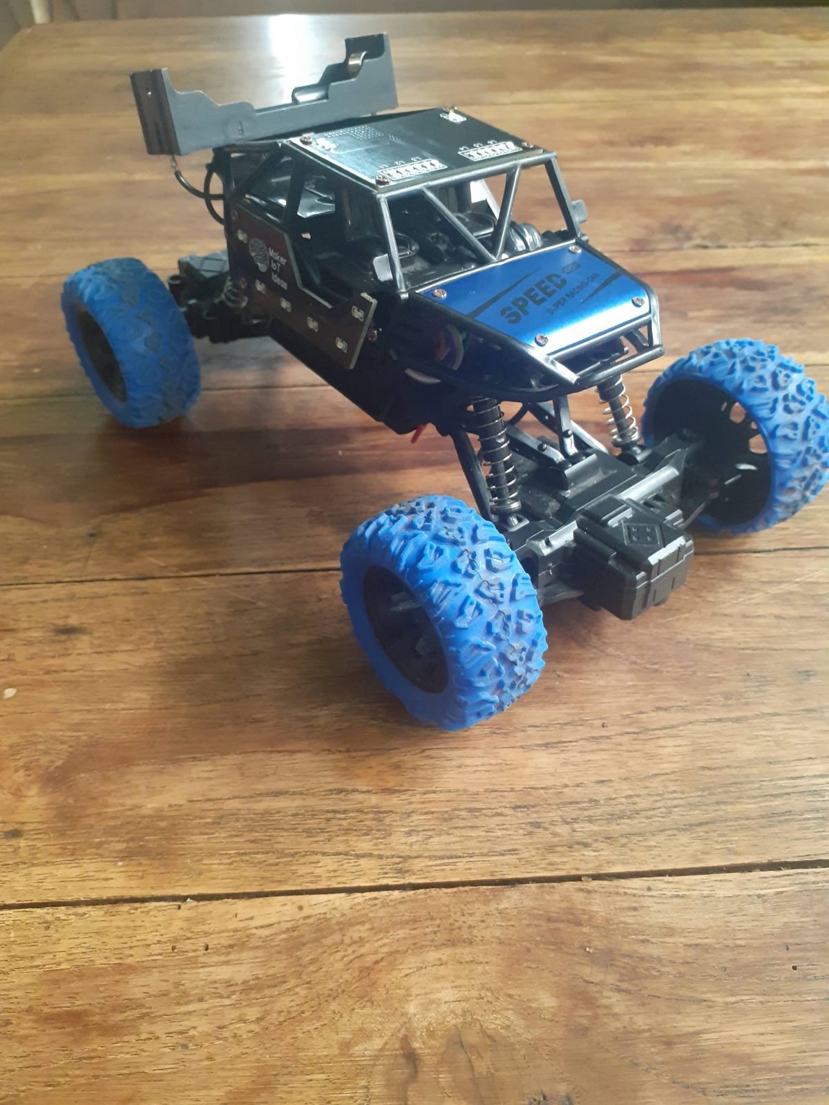
The “almost completed ” Robotic Toy Car
With the completion of the side-panels, it was also time to start work on the power wiring and other essential components of the project, which will get their own detailed post in a few days.
the “almost completed” project
Some details on the construction: The toy originally came with a single 500mA 14500 cell, which unfortunately stopped working very soon after only a few uses… This was however one of the reasons why the entire project happened in the first place, so no complaints there.
I decided to replace it with a 18560 cell with a capacity of about 1900mA. This cell is much bigger however, and I had to think of where to place it. I decided to put it on the roof, sort of emulating a “spoiler”.
Some of the next parts of the project will be the remote control unit, which will basically be an ESP8266 running ESP-Now protocol, as well as a decent battery charging and power distribution circuit, that will protect the Lipo cell from over charging and discharging, as well as provide sufficient power for all the added electronics in the toy car.
“But you said it was Robotic, so why have a remote control?”
The initial plan for the project did indeed say robotic, but it is also designed to be a learning platform, especially to teach coding. With that in mind, it is definitely better to keep things simple for now, and add sensors and more capabilities later on, especially as I am actually planning to replace the main MCU board with a more powerful ESP32 in a next version anyway.
The car body is also extremely cramped, and does not have any space for mounting sensors at all. I plan to remedy that by designing and 3d-printing a whole new custom body shell later… providing that my young friend actually stays interested enough to learn the coding… If he doesn’t, he will as least have a very interesting looking custom remote controlled toy car.
Manufacturing the PCB
The PCB for this project is currently on its way from China, after having been manufactured at PCBWay. Please consider supporting them if you would like your own copy of this PCB, or if you have any PCB of your own that you need to be manufactured.
If you would like to have PCBWAY manufacture one of your own, designs, or even this particular PCB, you need to do the following… 1) Click on this link 2) Create an account if you have not already got one of your own. If you use the link above, you will also instantly receive a $5USD coupon, which you can use on your first or any other order later. (Disclaimer: I will earn a small referral fee from PCBWay. This referral fee will not affect the cost of your order, nor will you pay any part thereof.) 3) Once you have gone to their website, and created an account, or login with your existing account,
4) Click on PCB Instant Quote
5) If you do not have any very special requirements for your PCB, click on Quick-order PCB
6) Click on Add Gerber File, and select your Gerber file(s) from your computer. Most of your PCB details will now be automatically selected, leaving you to only select the solder mask and silk-screen colour, as well as to remove the order number or not. You can of course fine-tune everything exactly as you want as well.
7) You can also select whether you want an SMD stencil, or have the board assembled after manufacturing. Please note that the assembly service, as well as the cost of your components, ARE NOT included in the initial quoted price. ( The quote will update depending on what options you select ).
8) When you are happy with the options that you have selected, you can click on the Save to Cart Button. From here on, you can go to the top of the screen, click on Cart, make any payment(s) or use any coupons that you have in your account.
Then just sit back and wait for your new PCB to be delivered to your door via the shipping company that you have selected during checkout.
In our last project, we started working on repurposing an old toy car. In this part, Robot Toy Car – The next steps, we will take a look at the controller board for this project and discuss some of the problems that we have encountered up to now. Most of the various components for this project are still in the prototype stage, but It is quite important to get them tested to verify the final designs.
There are quite a few unique challenges in a project like this, which looks quite easy to solve but turn out to become quite challenging to get working just right in practice…
One of the most important, as well as the most frustrating part, turned out to be the H-Bridge Motor controller. The first prototype of this was introduced in the first part of this project. While functional on paper, as well as working quite well in real life, (when tested with an Arduino, as well as manually), It performs extremely poorly when used with the actual controller for this project, an ESP8266 12-E…
What could the reason be? How will I fix it…? The answers to that will be provided in a follow-up post. For now, let us take a look at the controller.
The unassembled ESP-8266 Controller board, straight from the factoryThe Assembled ESP-8266 Controller board.
The Controller Board, details
Space inside the toy car is at a premium, so from the start, it was important to design a PCB that was small enough to fit, while also taking into consideration functionality, as well as all additional add-on components to ultimately be fitted to the project.
With this in mind, I have decided on the ESP-8266, which, while bigger than an Atmega328, does offer a few additional features, like WiFi, and ESP-Now, which will greatly help in controlling and even updating firmware OTA. The ESP-8266 does however also have a few serious flaws in this design, like limited useable GPIO pins, a 3.3v working voltage requirement, and quite high operating current requirements.
As the toy will likely not be used continuously, as well as the fact that it will run on batteries, which, can be replaced or recharged, I did not worry too much about the power issue. As far as the limited GPIO, that is where I2C comes in… It is quite easy to expand the GPIO with an IO Expander or two…
My main problem came in the form of the CH340G USB-to-UART converter chip. It seems like there must be quite a lot of counterfeit versions of these around, as none of the chips that I purchased, from many different suppliers, actually functioned, with the best one actually providing a USB port, but, when investigating with a logic analyser, the Rx and Tx lines of the UART, generating garbage…
Replacing it with a known working chip from a NodeMCU V1 board, magically solved the problem, verifying the PCB circuit as correct and working, and also proving that the purchased chips are definitely fake!
This was easily repaired by temporarily soldering jumper cables to the Rx and Tx lines on the ESP-8266, and using an external UART-to-USB converter to upload the initial sketch to the device. Future updates will be OTA, so not a problem in the long run anyway.
Controller Schematic
The controller schematic, above, is basically a rearranged stock NodeMCU v1 circuit, with the only difference being that only specific pins were broken out onto header pins. These will be used for controlling the two H-Bridges, and provide PWM as well as access to the I2C bus.
Software
Due to the fact that this controller is still definitely considered a prototype, my main focus is definitely on getting the control software sorted out first. That way, at least in my opinion, I can then focus on hardware issues responding to verified software inputs, without having to do both at the same time.
As mentioned before, I require OTA capability to upload new firmware to the device, so my starting point was the BasicOTA sketch provided with the Arduino IDE. This sketch was modified to perform some additional functionality, such as controlling the H-Bridges, PWM as well as a roof-mounted “status panel” with LED’s that also doubles as a visual display, to give a bit of colour to the project.
The “status panel” will be shown in a future post, however, with the only mention of it here being that it is I2C controlled, and based on a PCF8574.
The BasicOTA sketch is listed below.
#include <ESP8266WiFi.h>
#include <ESP8266mDNS.h>
#include <WiFiUdp.h>
#include <ArduinoOTA.h>

#ifndef STASSID
#define STASSID "your-ssid"
#define STAPSK  "your-password"
#endif

const char* ssid = STASSID;
const char* password = STAPSK;

void setup() {
  Serial.begin(115200);
  Serial.println("Booting");
  WiFi.mode(WIFI_STA);
  WiFi.begin(ssid, password);
  while (WiFi.waitForConnectResult() != WL_CONNECTED) {
    Serial.println("Connection Failed! Rebooting...");
    delay(5000);
    ESP.restart();
  }

  // Port defaults to 8266
  // ArduinoOTA.setPort(8266);

  // Hostname defaults to esp8266-[ChipID]
  // ArduinoOTA.setHostname("myesp8266");

  // No authentication by default
  // ArduinoOTA.setPassword("admin");

  // Password can be set with it's md5 value as well
  // MD5(admin) = 21232f297a57a5a743894a0e4a801fc3
  // ArduinoOTA.setPasswordHash("21232f297a57a5a743894a0e4a801fc3");

  ArduinoOTA.onStart([]() {
    String type;
    if (ArduinoOTA.getCommand() == U_FLASH) {
      type = "sketch";
    } else { // U_FS
      type = "filesystem";
    }

    // NOTE: if updating FS this would be the place to unmount FS using FS.end()
    Serial.println("Start updating " + type);
  });
  ArduinoOTA.onEnd([]() {
    Serial.println("\nEnd");
  });
  ArduinoOTA.onProgress([](unsigned int progress, unsigned int total) {
    Serial.printf("Progress: %u%%\r", (progress / (total / 100)));
  });
  ArduinoOTA.onError([](ota_error_t error) {
    Serial.printf("Error[%u]: ", error);
    if (error == OTA_AUTH_ERROR) {
      Serial.println("Auth Failed");
    } else if (error == OTA_BEGIN_ERROR) {
      Serial.println("Begin Failed");
    } else if (error == OTA_CONNECT_ERROR) {
      Serial.println("Connect Failed");
    } else if (error == OTA_RECEIVE_ERROR) {
      Serial.println("Receive Failed");
    } else if (error == OTA_END_ERROR) {
      Serial.println("End Failed");
    }
  });
  ArduinoOTA.begin();
  Serial.println("Ready");
  Serial.print("IP address: ");
  Serial.println(WiFi.localIP());
}

void loop() {
  ArduinoOTA.handle();
}
Controlling the Toy Car Robot
Controlling the Toy Car is a complicated question, with many ideas jumping into my mind, only to be pushed aside by technical issues, as well as real-world constraints on what is physically possible to be mounted on the plastic body of the toy car, space available on the inside, as well as not interfering with suspensions, springs, turning wheels etc.
The chassis of the toy car
As is clearly visible, there is really not a lot of space available here for sensors. Mounting sensors to the body will also provide a bit of a challenge, as well as won’t really look nice either…
I have thus decided to implement remote control for the time being, and later, maybe after 3d-printing a more suitable body, to add sensors for autonomous functionality. The ESP-Now protocol will be used extensively for the remote control, as, in my opinion, it required no additional hardware, is quite fast, as well as being extremely easy to use. It does however make it necessary to use another ESP deice in the remote control unit.
Manufacturing the PCB
The PCB for this project is currently on its way from China, after having been manufactured at PCBWay. Please consider supporting them if you would like your own copy of this PCB, or if you have any PCB of your own that you need to be manufactured.
If you would like to have PCBWAY manufacture one of your own, designs, or even this particular PCB, you need to do the following… 1) Click on this link 2) Create an account if you have not already got one of your own. If you use the link above, you will also instantly receive a $5USD coupon, which you can use on your first or any other order later. (Disclaimer: I will earn a small referral fee from PCBWay. This referral fee will not affect the cost of your order, nor will you pay any part thereof.) 3) Once you have gone to their website, and created an account, or login with your existing account,
4) Click on PCB Instant Quote
5) If you do not have any very special requirements for your PCB, click on Quick-order PCB
6) Click on Add Gerber File, and select your Gerber file(s) from your computer. Most of your PCB details will now be automatically selected, leaving you to only select the solder mask and silk-screen colour, as well as to remove the order number or not. You can of course fine-tune everything exactly as you want as well.
7) You can also select whether you want an SMD stencil, or have the board assembled after manufacturing. Please note that the assembly service, as well as the cost of your components, ARE NOT included in the initial quoted price. ( The quote will update depending on what options you select ).
8) When you are happy with the options that you have selected, you can click on the Save to Cart Button. From here on, you can go to the top of the screen, click on Cart, make any payment(s) or use any coupons that you have in your account.
Then just sit back and wait for your new PCB to be delivered to your door via the shipping company that you have selected during checkout.
Most Makers and electronics enthusiasts may already know of the RA-02 LoRa Module. Many of them might own an RA-02 Breakout module or two… For those who do, they will surely know about the problems encountered with using this particular breakout module…
The RA-02 module, in itself, is a great piece of kit, and when used on a custom PCB, which was designed with all the little secrets of this module taken into consideration, is a pleasure. Using the RA-02 breakout module, in its existing form factor, does however present quite a few unique challenges, which, if you are unaware of them, can cause quite a few frustrating moments, or even result in permanent damage to the module…
1) The module is based on the SX1278 chip from Semtech and is a 3v device. The IO pins are NOT 5v compatible but seem to work for a few hours or so when used with 5v… This causes many people, especially on Youtube, to assume that it is ok to send 5v logic signals to this module…
I have still not seen any Youtube video telling viewers to at least use a resister divider or logic converter… People just don’t know, and those that know seem to be keeping quiet!
Adding logic converters is in fact specified by the datasheet.
2) Adding logic converters means adding additional wiring, and for a breadboard based project, that adds to the complexity.
3) You have a total of 4 ground pins that need to be connected. not connecting all of them, causes funny things to happen, from overheating down to failure… ( My personal experience while researching this project)
4) The existing breakout module is not breadboarding compatible, resulting in a floating assembly with wires going everywhere, which results in unstable connections etc…
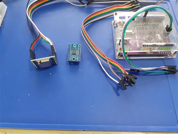
Basically something similar to the picture below:
In this picture, I have an existing RA-02 Breakout Module, with an 8 channel Logic converter and an Arduino Uno clone, along with all the needed wiring to make this setup possible… Quite a lot of wires indeed…
My solution:
I design and use quite a few LoRa PCBs and on all of them, I implement logic conversion using the BSS138 N-MOS Mosfet and 10k resistors. It is a cheap and reliable solution, but it can take up quite a lot of space on a PCB, as this means 11 Mosfets and 22 10k resistors if I were to provide level conversion to all of the RA-02’s GPIO and IO pins…
I also have the constant problem of many unnecessary wires, many of which sometimes fail straight out of the box, when prototyping something. I partly solved that by designing a few dedicated PCB solutions, but that is not always ideal,
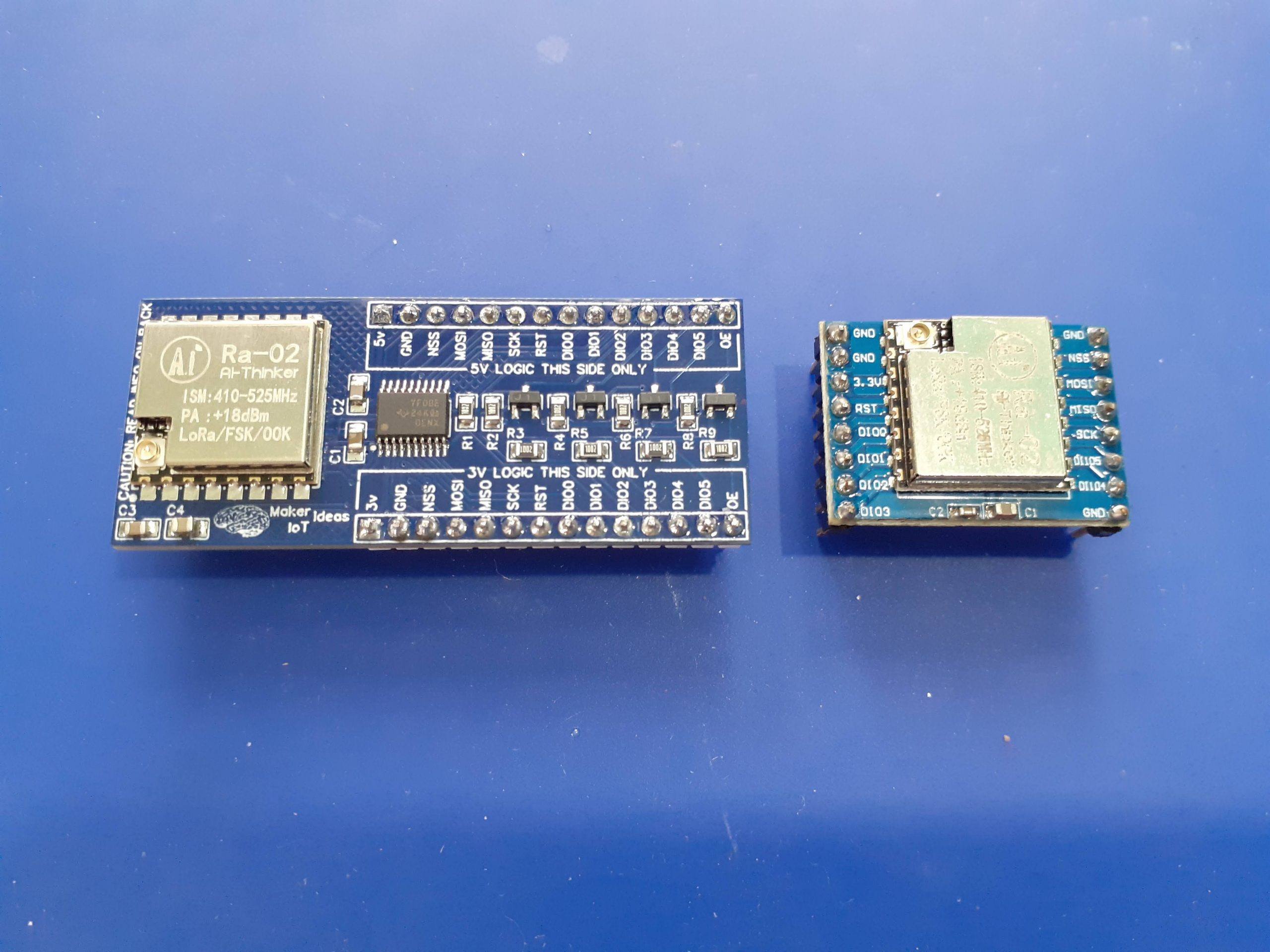
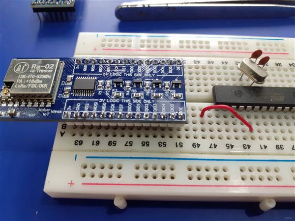
Using a dedicated Logic Converter IC, and Mosfet based converters to make up the difference, on a breadboard compatible module, seemed like a good idea, so I went ahead and designed the following solution:
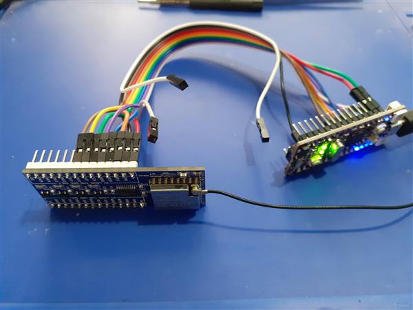
The breakout board module is breadboard compatible, and also has clearly marked pins to indicate the 3v and 5v sides of the module.
For my first test, I decided to test with an Arduino Uno Clone, since that is what most Makers and students will have access to. I used Cytron’s Maker Uno platform, which is equipped with some added goodies, in the form of diagnostic LED etc to make prototyping a lot easier.
As we can clearly see, It is only necessary to connect to the 5v logic side of the module, as well as provide 3v and 5v + GND to the module
In this test, I used Sandeep Mistry’s LoRa Library, with the Arduino IDE to do a quick test sketch.
As we can see, you need quite a lot more wires to make this work. It is also worth noting that we have only 8 level converters on this ATMEGA328P PCB, in order to use all of the RA-02’s GPIO, we will need to add an additional external logic converter as well.
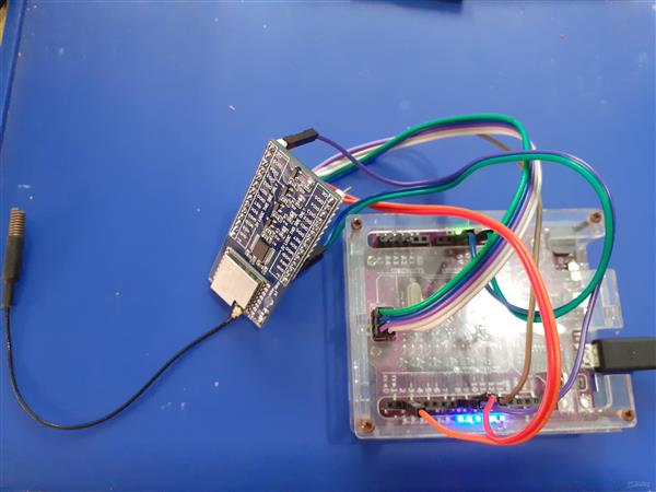
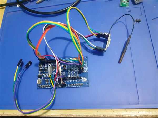
For my second test, I decided to be a bit brave, and try to use the new Raspberry Pi Pico ( RP2040 Microprocessor ). I have quite a few of them lying around and have never really done a lot with them, due to the fact that I do not really like using MicroPython or CircuitPython, and also because the recently released Arduino Core for the RP2040 still being quite new… I decided to use a development board that I recently bought from Cytron, the Maker Nano RP2040, as it has all the added diagnostic features to make my life a bit easier, I will also include a test with an original Pi Pico board, to make it more accessible to everyone out there.
Once again, I used Sandeep Mistry’s LoRa Library, with the exact same Arduino sketch, used for the Maker Uno test. (I obviously needed to change the pin numbers though, as the RP2040 uses different pins for its SPI interface).
Maker Nano RP2040 RA-02 Breakout Module
NSS 17
MOSI 19
MISO 16
SCK 18
RST 9
DIO0 8
In this case, we DO NOT need the OE pin, as the RP2040 is a native 3v device. The level converter can thus stay disabled, with its pins in tri-state ( high impedance ) mode.
If we look at the code, it is similar to the Maker Uno’s code, with only the Pin declarations needing a change
#include <SPI.h> // include libraries
#include <LoRa.h>
const int csPin = 17; // LoRa radio chip select
const int resetPin = 9; // LoRa radio reset
const int irqPin = 8; // change for your board; must be a hardware interrupt pin
byte msgCount = 0; // count of outgoing messages
int interval = 2000; // interval between sends
long lastSendTime = 0; // time of last packet send
// Note that SPI has different names on the RP2040, and it has 2 SPI ports. We used port 0
// CIPO (Miso) is on pin 16
// COPI (Mosi) is on pin 19
// SCK is on pin 18
// CE/SS is on pin 17, as already declared above
I did not use a breadboard, in order to make things as easy as possible.
To make things a bit easier, without having to resort to using a breadboard, I decided to do the Original Pi Pico test using the Maker Pi Pico PCB. This PCB is basically a big breakout module, with detailed pin numbers and some diagnostic LEDs, but it also uses a native Pi Pico, soldered directly to the PCB, by means of the castellated holes… So, While technically not being a true standalone Pico, It makes my life easier and was thus used for the test, as I can be sure that the pins are labelled exactly the same as on the original Pico.
The code used for the Maker Nano RP2040 works perfectly, with no changes required.
This post is getting quite long by now, so I have decided not to include my tests of the ESP-12E ( NodeMCU ) or ESP32 development boards here as well… They also function as expected.
In Summary
When I started this project, I set out to solve a problem ( personal to me ), that could potentially help a lot of other people use the RA-02 Module for more projects and tasks. The Breakout module in its current form can also be used with the RA-01h module (915Mhz Module) without any changes. All GPIO pins are broken out, and accessible through full logic converted pins on both sides of the breakout module.
I hope that this will be useful to someone. I am also not releasing the full schematics at this stage, as I may decide to make some minor cosmetic changes in the near future.
The PCB can however be ordered from PCBWay in its current form and works 100% as expected. The BOM file is available with the ordered PCB as usual.
This PCB was manufactured at PCBWAY. The Gerber files and BOM, as well as all the schematics, will soon be available as a shared project on their website. If you would like to have PCBWAY manufacture one of your own, designs, or even this particular PCB, you need to do the following… 1) Click on this link 2) Create an account if you have not already got one of your own. If you use the link above, you will also instantly receive a $5USD coupon, which you can use on your first or any other order later. (Disclaimer: I will earn a small referral fee from PCBWay. This referral fee will not affect the cost of your order, nor will you pay any part thereof.) 3) Once you have gone to their website, and created an account, or login with your existing account,
4) Click on PCB Instant Quote
5) If you do not have any very special requirements for your PCB, click on Quick-order PCB
6) Click on Add Gerber File, and select your Gerber file(s) from your computer. Most of your PCB details will now be automatically selected, leaving you to only select the solder mask and silk-screen colour, as well as to remove the order number or not. You can of course fine-tune everything exactly as you want as well.
7) You can also select whether you want an SMD stencil, or have the board assembled after manufacturing. Please note that the assembly service, as well as the cost of your components, ARE NOT included in the initial quoted price. ( The quote will update depending on what options you select ).
8) When you are happy with the options that you have selected, you can click on the Save to Cart Button. From here on, you can go to the top of the screen, click on Cart, make any payment(s) or use any coupons that you have in your account.
Then just sit back and wait for your new PCB to be delivered to your door via the shipping company that you have selected during checkout.
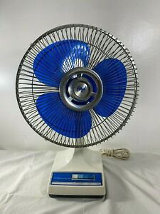
Desk or floor-standing fans are one of those appliances that will be present in almost every home or office. Some of the newer ones may already have remote control of some sort, while the older models won’t. It is however quite easy to do a retro-fitted controller to most of them, and at the same time, give them some (limited) intelligence.
Your typical oscillating fan does not have a lot of intelligence built-in. They normally consist of an electrical motor, with three separate windings, of varying inductance ( meaning the number of turns in the coil of wire will change the magnetic field generated, thereby changing the speed of the electric motor).
These windings have one common side, where all three of them are connected together, and the other three are separated. Normally the live wire from your mains supply (220v AC in my case) will go to this common connection. The neutral wire will go to the common of a four-position mechanical switch, with each winding going to one of positions 2,3 and 4 ( This results in a 3-speed configuration, with the first switch being off). It is also VERY important to note that this mechanical switch is hardware interlocked, meaning that ONLY one switch can be on at any given time… This is to ensure that electricity can only flow through one winding at a time. If you were to send electricity through multiple windings at the same time, the motor will still work, but not for very long…
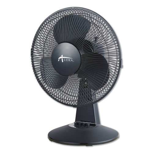
A more modern Oscillating Fan
In order to automate an oscillating fan, we would thus need a way to switch the separate windings on and off, while preventing other windings from getting power at the same time. I chose to do this with SPST relays, as a proof of concept, and plan to design it with DPDT relays at a later stage to implement a proper hardware interlock, in addition to the software interlock implemented in the control software ( more on that later)
My requirements for the device are the following: 1) Must operate from mains power, using the existing power cord of the fan. 2) Must allow for local operation of the fan using the existing control buttons. 3) Must be able to update firmware OTA, and have WiFi connectivity for control via Home Assistant or MQTT 4) Must be capable of adding support for ESP Now protocol at a later stage 5) The fan must not have any visible modifications on the outside
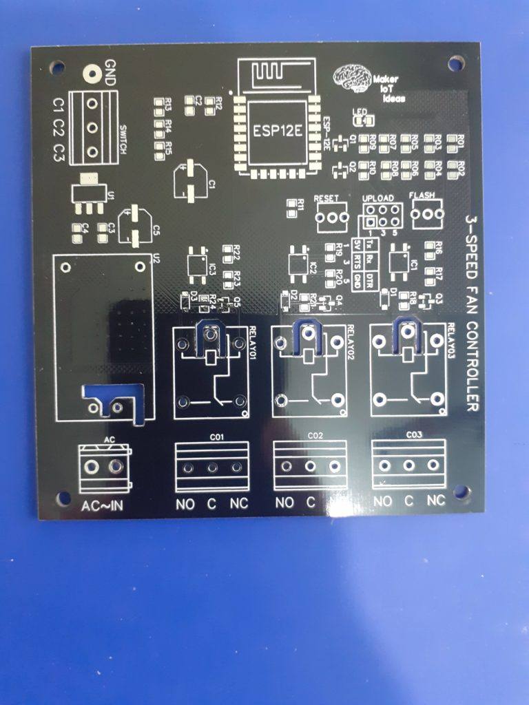
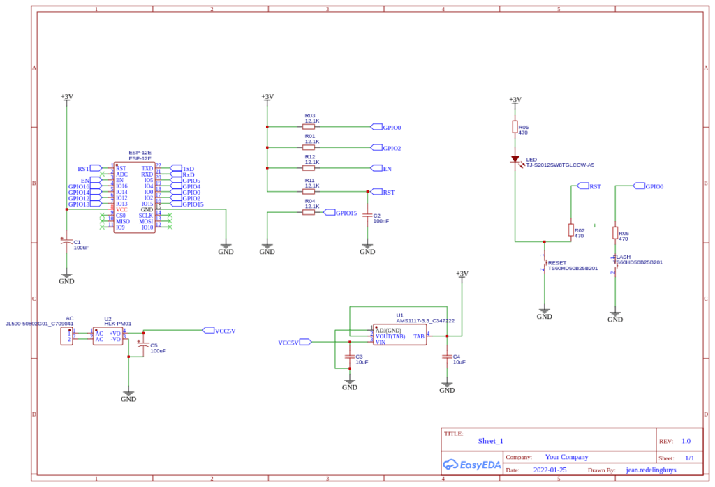
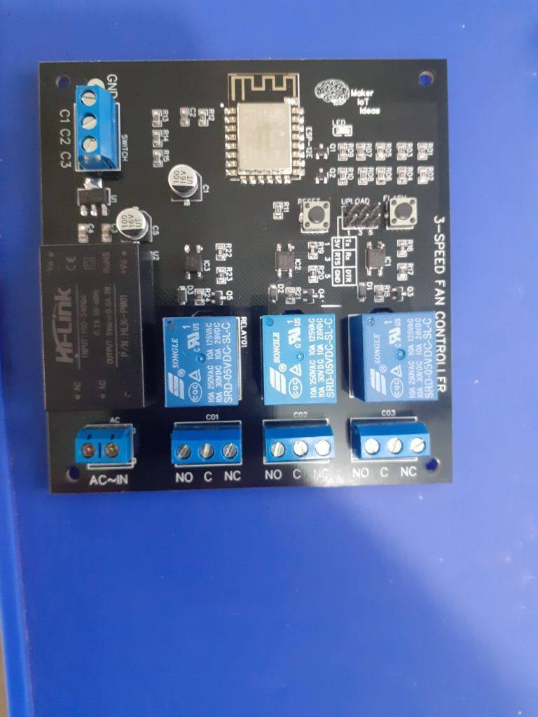
The 3 speed Fan controller PCB
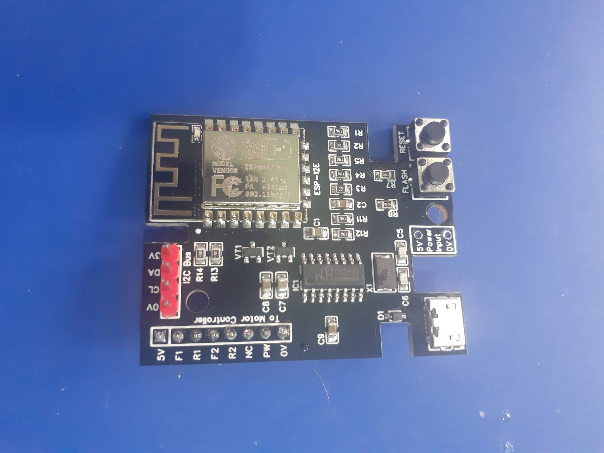
Taking all of my requirements into consideration, I have designed the following PCB to take care of my needs. As I do not require a lot of GPIO for this ( only 3 outputs, and 3 inputs ), I have decided to use an ESP8266-12E module from Espressif ( manufactured by AITinker, not sponsored by either company). This module is relatively cheap and has more than enough flash memory, RAM, as well as GPIO available.
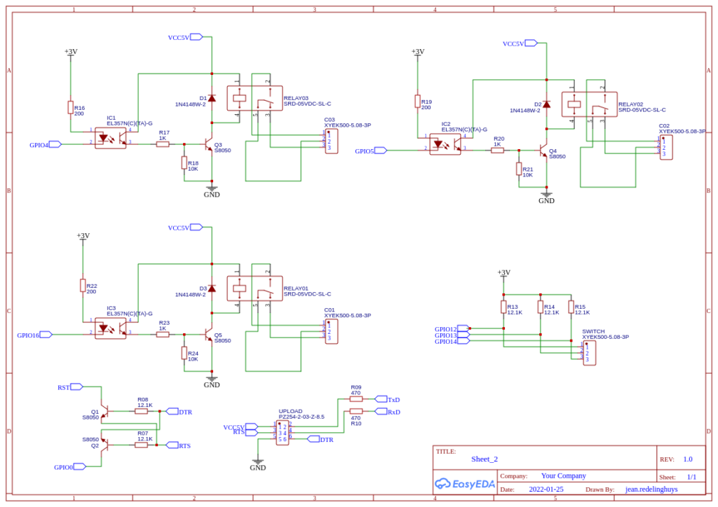
Circuit Diagram – Page 1Circuit Diagram – Page 2
As we can see, the circuit is minimal, with optical isolation on the relay drivers, a programming header, and a 3-way input for the mechanical switch.
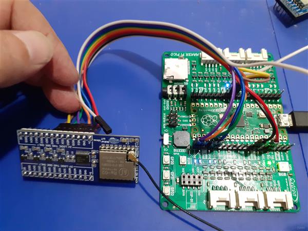
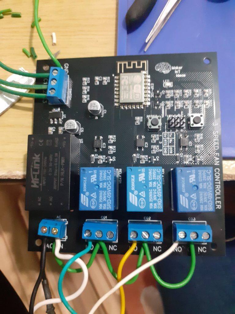
The completed PCB, wired to the oscillating fan
As seen in the picture above, the wiring is quite simple, with the neutral wire looped to the common terminal of each relay (I had only green mains rated cable available, will replace it later with a proper white cable to keep to wiring standards). Black is live, with one wire going to the mains socket, and the other to the common of the motor coil windings. Light blue, yellow and white ( connected to the N/O terminal of the relays) corresponds to speeds 1, 2 and 3 of the fan.
At the top of the board, 3 wires go to the mechanical switch and a fourth to DC ground. (Note that there is no AC voltage on any of the switches. )
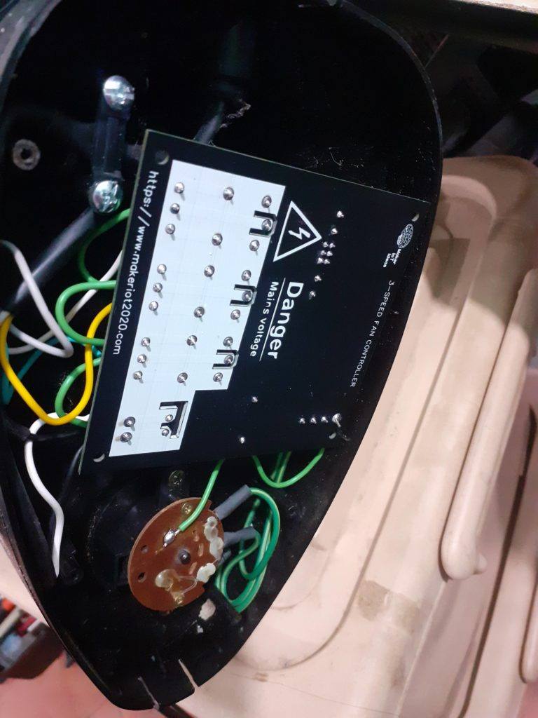
Mounting the PCB in the base of the oscillating fan
The PCB is mounted in the base of the fan while taking care to ensure that no AC cables are near the DC components. The ESP8266 chip is oriented to the side ( logo side of PCB ) to prevent interference to the WiFi signal. The mechanical switch is mounted into its original position, and its wires are routed away from any AC carrying wires to prevent interference.
It is important to note here that the firmware for the PCB was uploaded before assembly. You should NOT attempt serial uploading while the device is connected to mains power under any circumstances. ( While I have taken every precaution to ensure that AC and DC components of the circuit are separated from each other, it is just common sense to not try to upload firmware with mains connected)
The completed PCB shows the Upload port near the right top corner.
Uploading firmware:
Initial uploading of firmware can be performed by connecting a USB-to-serial adapter to the UPLOAD port and providing 5v and ground from the USB-to-serial adapter. The flash button is held down, and the board is reset, after which you can proceed with uploading, alternatively, you can also connect the DTR and RTS lines from the serial adapter to automatically reset the board and enter flash mode as needed. ( If your adapter supports this of course).
ESPHome configuration
The YAML configuration for ESPHome is listed below:
This PCB was manufactured at PCBWAY. The Gerber files and BOM, as well as all the schematics, will soon be available as a shared project on their website. If you would like to have PCBWAY manufacture one of your own, designs, or even this particular PCB, you need to do the following… 1) Click on this link 2) Create an account if you have not already got one of your own. If you use the link above, you will also instantly receive a $5USD coupon, which you can use on your first or any other order later. (Disclaimer: I will earn a small referral fee from PCBWay. This referral fee will not affect the cost of your order, nor will you pay any part thereof.) 3) Once you have gone to their website, and created an account, or login with your existing account,
4) Click on PCB Instant Quote
5) If you do not have any very special requirements for your PCB, click on Quick-order PCB
6) Click on Add Gerber File, and select your Gerber file(s) from your computer. Most of your PCB details will now be automatically selected, leaving you to only select the solder mask and silk-screen colour, as well as to remove the order number or not. You can of course fine-tune everything exactly as you want as well.
7) You can also select whether you want an SMD stencil, or have the board assembled after manufacturing. Please note that the assembly service, as well as the cost of your components, ARE NOT included in the initial quoted price. ( The quote will update depending on what options you select ).
8) When you are happy with the options that you have selected, you can click on the Save to Cart Button. From here on, you can go to the top of the screen, click on Cart, make any payment(s) or use any coupons that you have in your account.
Then just sit back and wait for your new PCB to be delivered to your door via the shipping company that you have selected during checkout.
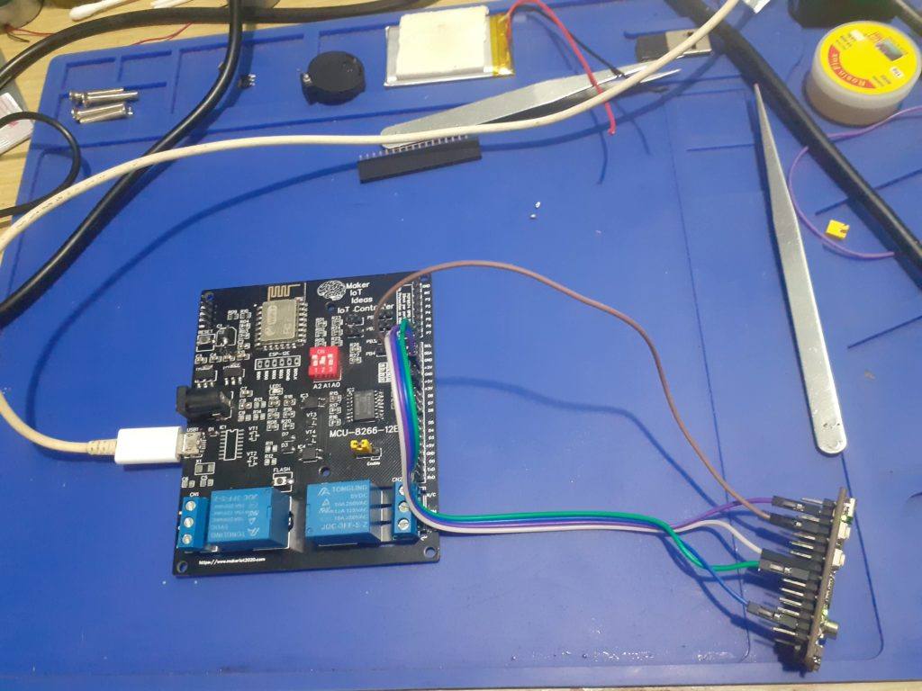
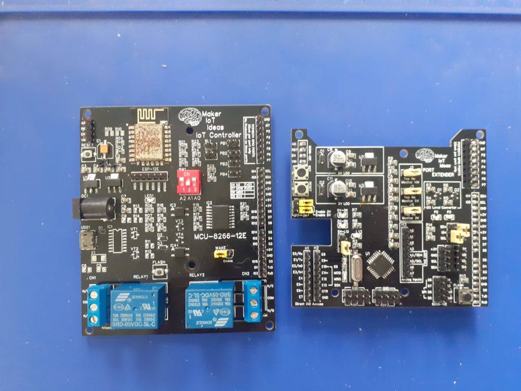
After quite a few experiments, and playing with a lot of ideas, we have finally produced and tested an almost final prototype for the MCU-8266-12E IoT Controller Port Extender Card. While the baseboard already has quite a lot of free GPIO pins for additional sensors and devices, It did however have quite a few issues, namely a lack of sufficient Power outputs, difficulty access to the I2C bus, as well as only 2 relay outputs. Granted that you do have access to unused pins on the PCF8574 Port Extender, We nonetheless decided that an add-on card would definitely make sense to allow this device to really be more useable.
While looking at various ideas for this card, the most flexible seemed to be the APE Protocol device as documented in ESPHome. They used a standard Arduino board for that, but we decided that, after testing it with an Arduino Nano, since it seems to work well, let us just design a dedicated PCB. It also looks much better as well 🙂
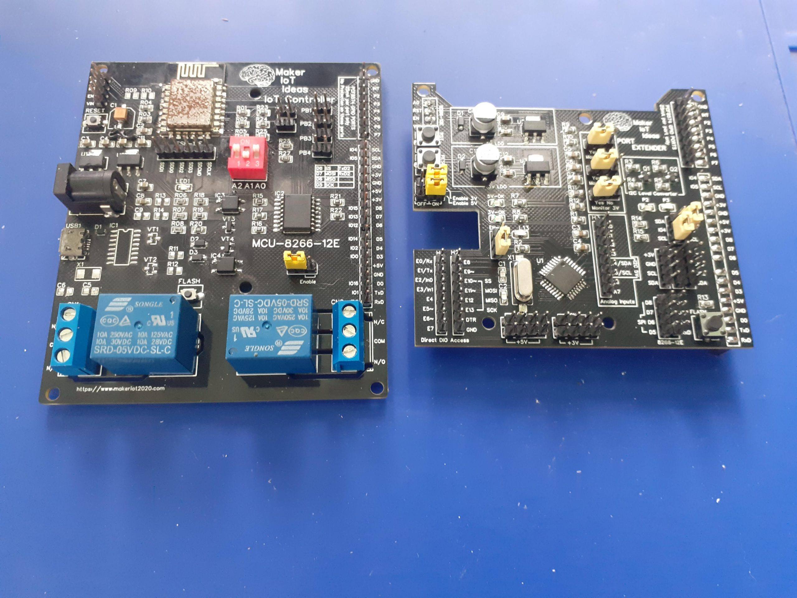
The beginning of the APE (Arduino Port Extender) Device. MCU-8266-12E with Arduino Nano (left) and MCU-8266-12E with the newly designed APE Card (right)
Some Features (Aside from being a fully functional Arduino clone as well)
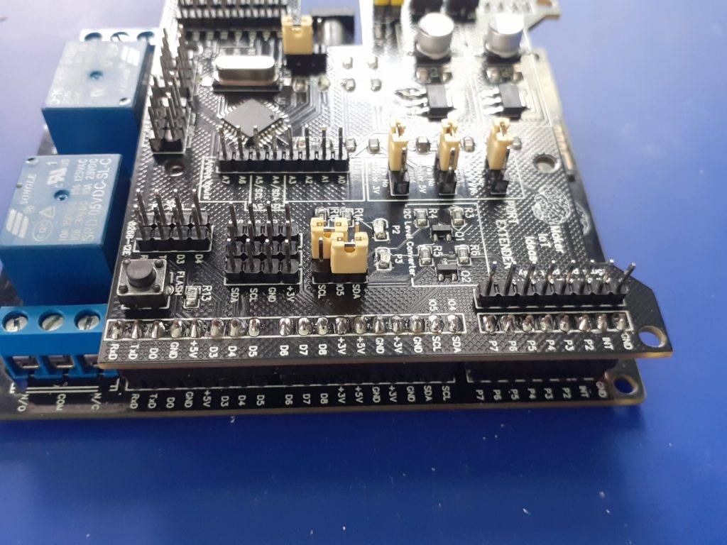
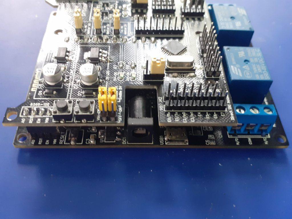
1). Dedicated LDO Regulators for 5v and 3.3v (800mA each), with jumpers to switch them on or off (receive power only from the IoT Motherboard). 2.) Dedicated Logic Level Converter on the I2C Bus ( This is sort of very much needed 🙂 The Atmega 328P-AU is running at 5v on this device, to enable it to run at 16Mhz.. and the ESP8266 on the Motherboard is a 3.3v device..
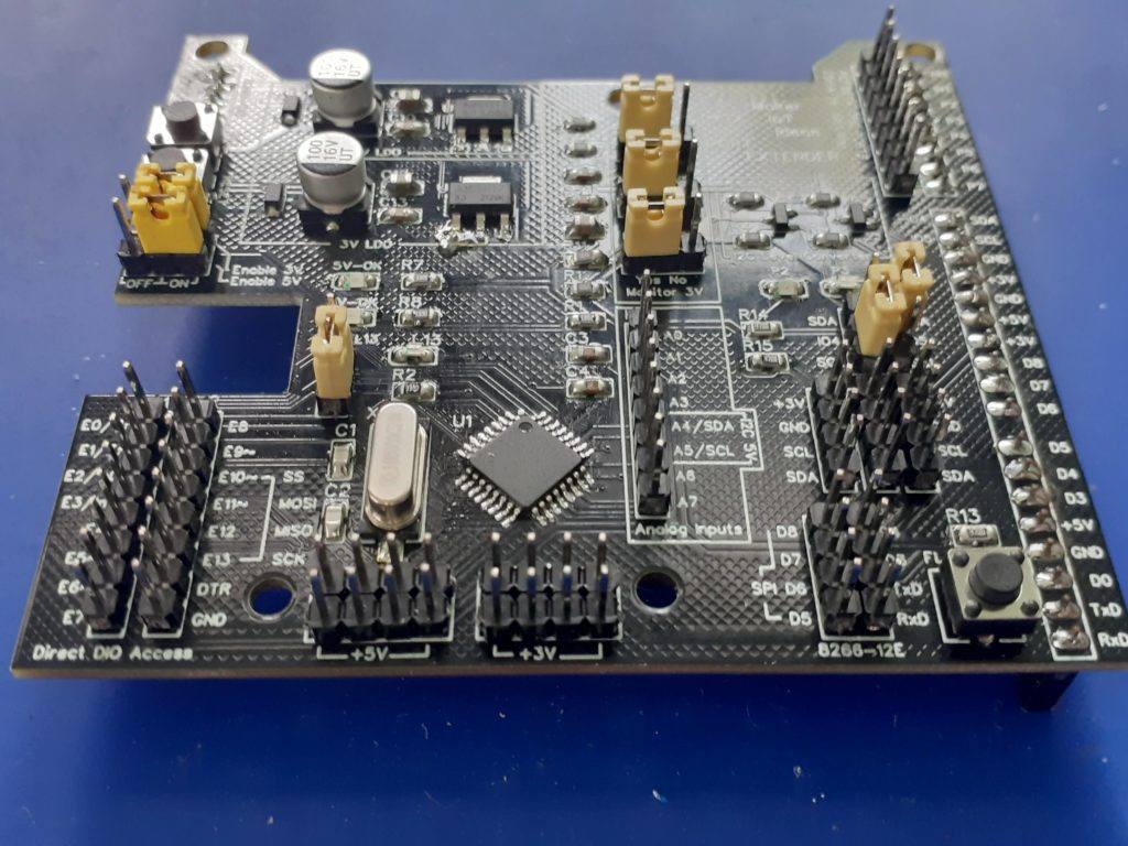
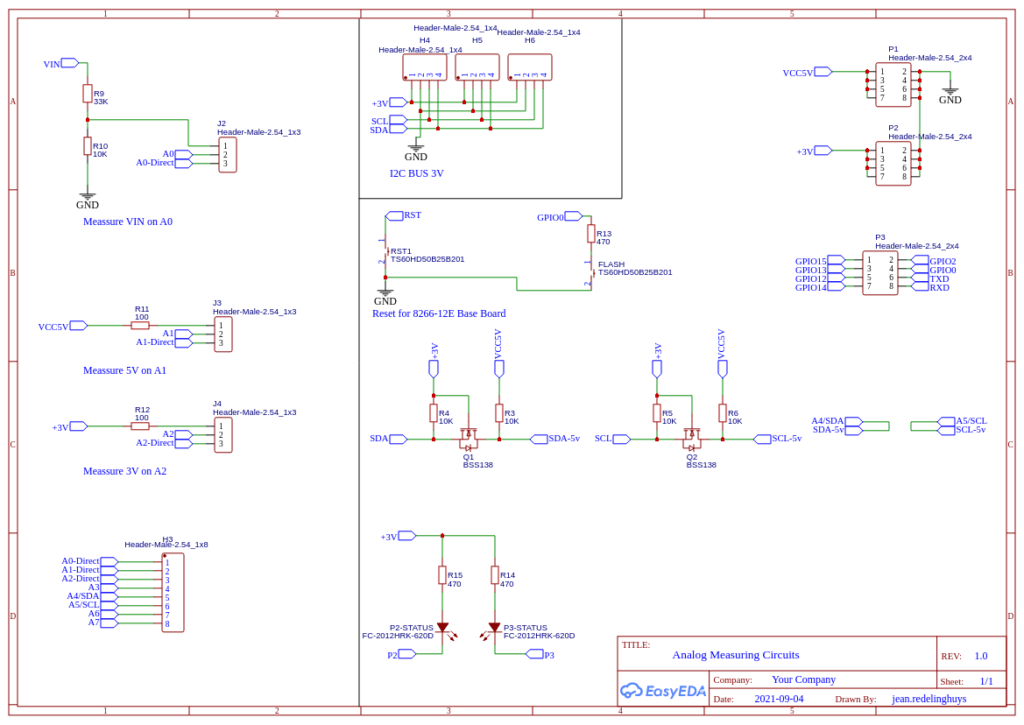
There are also 3x 3.3V I2C Headers, complete with 3.3v and Ground, as well as a single 5v I2C header 3). 8 Analog Inputs ( While practically you can only use 6 of these if you use I2C ) 4). Voltage Divider provided on A0 to measure VIN ( to be safe, we calculated the resistors for 22v) 5). 100R current limiting resistor on A1 and A2, to measure 5v and 3.3v as well… Analog inputs A0, A1 and A2 can be switched back to normal operation by changing the jumper at J2,J3 or J4 from On to Off. 6). 12 Digital Inputs/Outputs (14 if you use D0 and D1 as well), as well as a Jumper to remove the LED on D13. 7). Full access to the PCF8574 and ESP8266 Pins from the motherboard below.
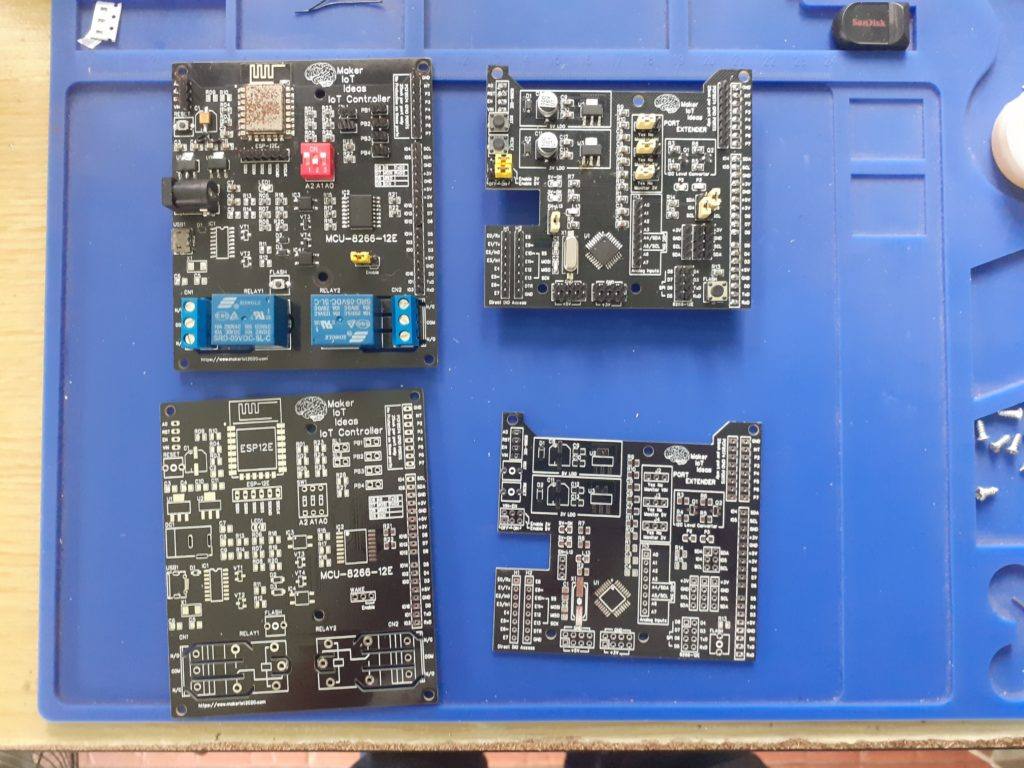
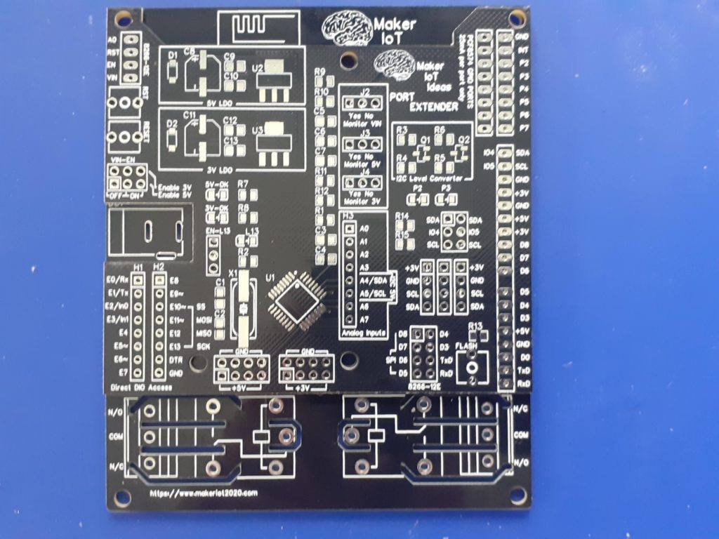
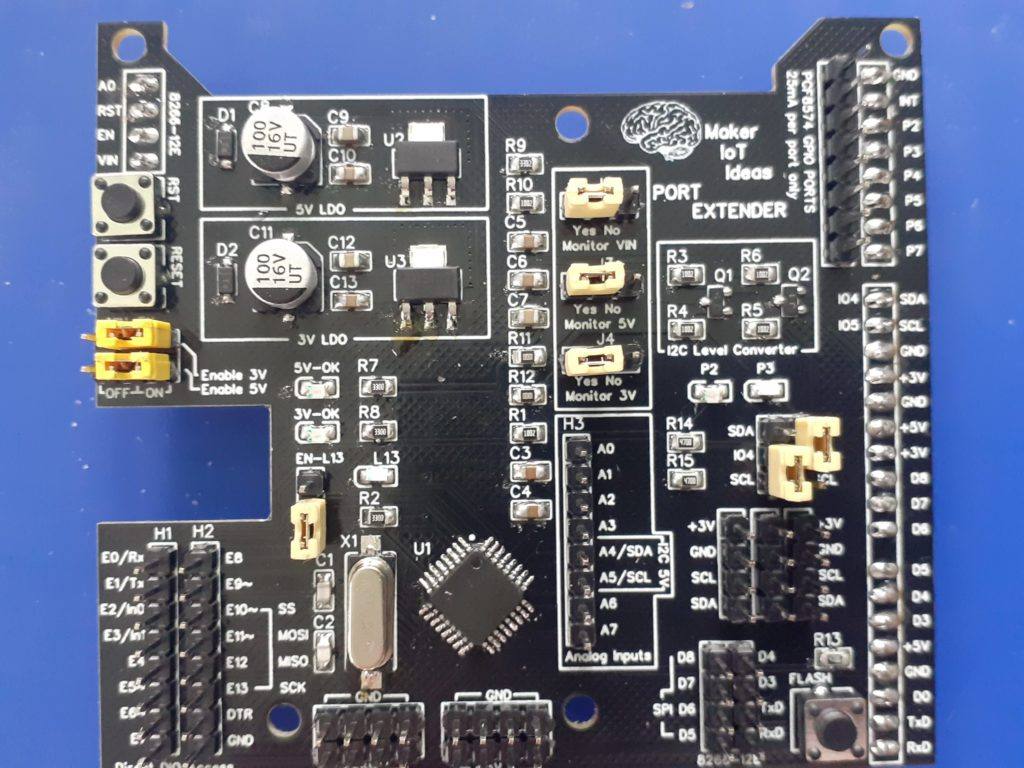
Pictures of the PCB
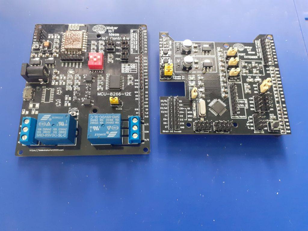
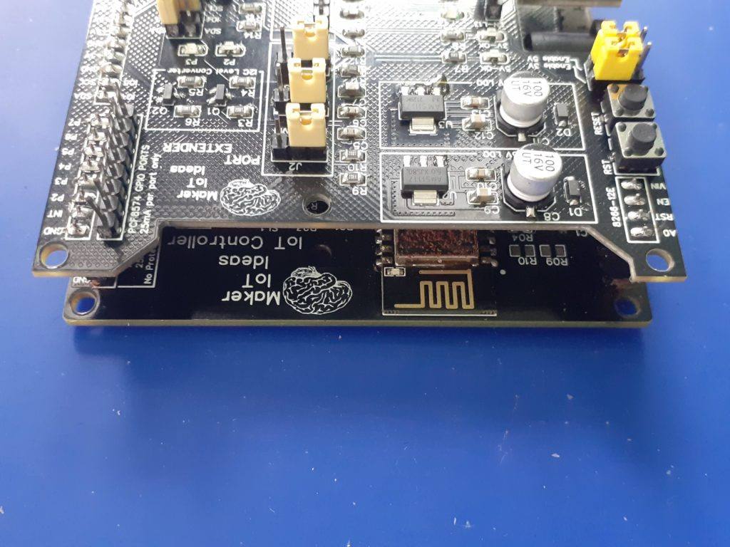
Side by side MCU-8266-12E (left) 8266-12E-Port Extender (right)
Side by side MCU-8266-12E (left) 8266-12E-Port Extender (right)
Side by side MCU-8266-12E (left) 8266-12E-Port Extender (right) [ with unpopulated PCB at bottom]
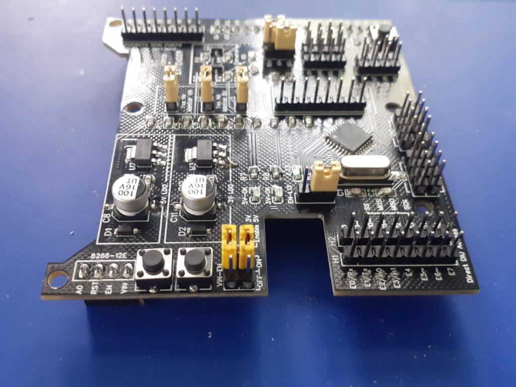
Blank PCB 8266-12E-Port Extender
Blank PCB MCU-8266-12E IoT Controller
Top view 8266-12E PE
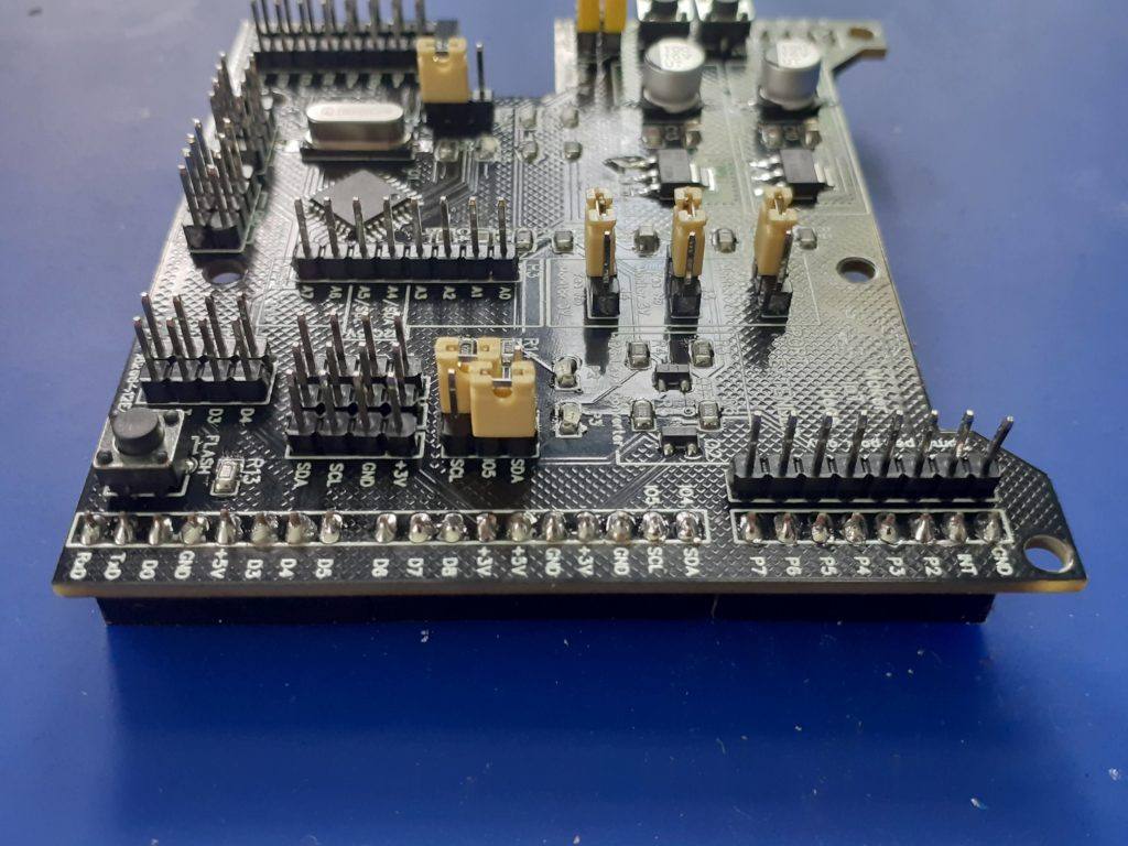
8266-12E-PE side view { from bottom)
Right side view – 8266-12E-PE
Left side view – 8266-12E-PE
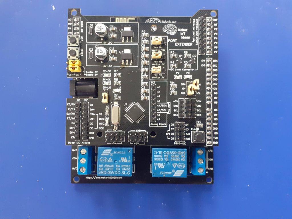
Stacked on-top-of MCU-8266-12E
Stacked – Top Side view
Stacked – Right side view
Stacked – Left side view
Pictures of the PCB, alone and with the MCU-8266-12E IoT controller
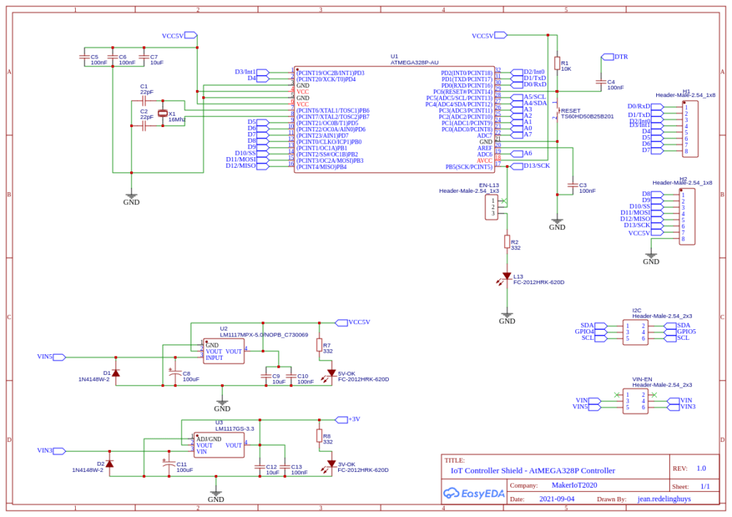
Circuit Diagram
ATMega328P-AU Circuit diagram with LDO Regulators, headers and supporting circuitry.Analog measuring circuitry, level converters and supporting circuitry and headers
Uploading Code to the ATMega328P
Uploading code to the device requires the use of either an ISCP programmer ( Arduino as ISP works well ) or in the case of a pre-boot loaded chip, a USB-to-Serial converter. We did not find it necessary to add a dedicated USB-to-Serial converter onto the PCB. It is quite easy enough to do any flashing with the tools mentioned above.
Make sure that the PCB is not stacked when doing this. ( This will prevent excessive current use of other components when you supply 5v to the PE card.
Procedure to upload using ICSP
During assembly, you are required to solder a single 90-degree bend pin header on the bottom side of the PCB, in the same hole as the board side edge of the RESET push-button. This will serve as the RESET Pin for the ISCP. Other connections are as follows:
H2 Header <- > ICSP Programmer MOSI (E11~) – MOSI ( or Pin 11 on Arduino as ISP ) MISO (E12 ) – MISO ( or Pin 12 on Arduino as ISP ) SCK (E13) – D13 (or Pin 13 on Arduino as ISP ) RESET – D10 (or Pin 10 on Arduino as ISP )
5v and Ground from Arduino as ISP or ISCP Programmer to any 5v and ground pin on the PE Card
Please note the description above for assembly of the RESET pin header
Procedure to upload using USB-to-Serial converter
H1 Header
E0/Rx <- to Tx of USB-to-Serial converter E1/Tx -> to Rx of USB-to-Serial converter
H2 Header
DTR <-> to DTR of USB-to-Serial converter [ This connection is needed for successful uploading. Don’t leave it out ]
5v and Ground from the USB-to-Serial converter to any 5v and ground pin on the PE Card
Testing with ESPHome APE protocol and the MCU-8266-12E IoT controller
The following Arduino Sketch needs to be uploaded to the device. It will allow the device to function as a custom I2C device. Feel free to change the I2C address in the sketch as you choose, but remember to use the same address in your ESPHome YAML configuration file
The following C header file needs to be uploaded to your Home Assistant ESPHome folder.
// Must disable logging if using logging in main.cpp or in other custom components for the
//  __c causes a section type conflict with __c thingy
// you can enable logging and use it if you enable this in logger:
/*
logger:
  level: DEBUG
  esp8266_store_log_strings_in_flash: False
  */

//#define APE_LOGGING

// take advantage of LOG_ defines to decide which code to include
#ifdef LOG_BINARY_OUTPUT
#define APE_BINARY_OUTPUT
#endif
#ifdef LOG_BINARY_SENSOR
#define APE_BINARY_SENSOR
#endif
#ifdef LOG_SENSOR
#define APE_SENSOR
#endif

static const char *TAGape = "ape";

#define APE_CMD_DIGITAL_READ 0
#define APE_CMD_WRITE_ANALOG 2
#define APE_CMD_WRITE_DIGITAL_HIGH 3
#define APE_CMD_WRITE_DIGITAL_LOW 4
#define APE_CMD_SETUP_PIN_OUTPUT 5
#define APE_CMD_SETUP_PIN_INPUT_PULLUP 6
#define APE_CMD_SETUP_PIN_INPUT 7
// 8 analog registers.. A0 to A7
// A4 and A5 not supported due to I2C
#define CMD_ANALOG_READ_A0 0b1000 // 0x8
// ....
#define CMD_ANALOG_READ_A7 0b1111 // 0xF

#define CMD_SETUP_ANALOG_INTERNAL 0x10
#define CMD_SETUP_ANALOG_DEFAULT 0x11

#define get_ape(constructor) static_cast<ArduinoPortExpander *>(constructor.get_component(0))

#define ape_binary_output(ape, pin) get_ape(ape)->get_binary_output(pin)
#define ape_binary_sensor(ape, pin) get_ape(ape)->get_binary_sensor(pin)
#define ape_analog_input(ape, pin) get_ape(ape)->get_analog_input(pin)

class ArduinoPortExpander;

using namespace esphome;

#ifdef APE_BINARY_OUTPUT
class ApeBinaryOutput : public output::BinaryOutput
{
public:
  ApeBinaryOutput(ArduinoPortExpander *parent, uint8_t pin)
  {
    this->parent_ = parent;
    this->pin_ = pin;
  }
  void write_state(bool state) override;
  uint8_t get_pin() { return this->pin_; }

protected:
  ArduinoPortExpander *parent_;
  uint8_t pin_;
  // Pins are setup as output after the state is written, Arduino has no open drain outputs, after setting an output it will either sink or source thus activating outputs writen to false during a flick.
  bool setup_{true};
  bool state_{false};

  friend class ArduinoPortExpander;
};
#endif

#ifdef APE_BINARY_SENSOR
class ApeBinarySensor : public binary_sensor::BinarySensor
{
public:
  ApeBinarySensor(ArduinoPortExpander *parent, uint8_t pin)
  {
    this->pin_ = pin;
  }
  uint8_t get_pin() { return this->pin_; }

protected:
  uint8_t pin_;
};
#endif

#ifdef APE_SENSOR
class ApeAnalogInput : public sensor::Sensor
{
public:
  ApeAnalogInput(ArduinoPortExpander *parent, uint8_t pin)
  {
    this->pin_ = pin;
  }
  uint8_t get_pin() { return this->pin_; }

protected:
  uint8_t pin_;
};
#endif

class ArduinoPortExpander : public Component, public I2CDevice
{
public:
  ArduinoPortExpander(I2CBus *bus, uint8_t address, bool vref_default = false)
  {
    set_i2c_address(address);
    set_i2c_bus(bus);
    this->vref_default_ = vref_default;
  }
  void setup() override
  {
#ifdef APE_LOGGING
    ESP_LOGCONFIG(TAGape, "Setting up ArduinoPortExpander at %#02x ...", address_);
#endif

    /* We cannot setup as usual as arduino boots later than esp8266
            Poll i2c bus for our Arduino for a n seconds instead of failing fast,
            also this is important as pin setup (INPUT_PULLUP, OUTPUT it's done once)
        */
    this->configure_timeout_ = millis() + 5000;
  }
  void loop() override
  {
    if (millis() < this->configure_timeout_)
    {
      bool try_configure = millis() % 100 > 50;
      if (try_configure == this->configure_)
        return;
      this->configure_ = try_configure;

      if (ERROR_OK == this->read_register(APE_CMD_DIGITAL_READ, const_cast<uint8_t *>(this->read_buffer_), 3))
      {
#ifdef APE_LOGGING
        ESP_LOGCONFIG(TAGape, "ArduinoPortExpander found at %#02x", address_);
#endif
        delay(10);
        if (this->vref_default_)
        {
          this->write_register(CMD_SETUP_ANALOG_DEFAULT, nullptr, 0); // 0: unused
        }

        // Config success
        this->configure_timeout_ = 0;
        this->status_clear_error();
#ifdef APE_BINARY_SENSOR
        for (ApeBinarySensor *pin : this->input_pins_)
        {
          App.feed_wdt();
          uint8_t pinNo = pin->get_pin();
#ifdef APE_LOGGING
          ESP_LOGCONFIG(TAGape, "Setup input pin %d", pinNo);
#endif
          this->write_register(APE_CMD_SETUP_PIN_INPUT_PULLUP, &pinNo, 1);
          delay(20);
        }
#endif
#ifdef APE_BINARY_OUTPUT
        for (ApeBinaryOutput *output : this->output_pins_)
        {
          if (!output->setup_)
          { // this output has a valid value already
            this->write_state(output->pin_, output->state_, true);
            App.feed_wdt();
            delay(20);
          }
        }
#endif
#ifdef APE_SENSOR
        for (ApeAnalogInput *sensor : this->analog_pins_)
        {
          App.feed_wdt();
          uint8_t pinNo = sensor->get_pin();
#ifdef APE_LOGGING
          ESP_LOGCONFIG(TAGape, "Setup analog input pin %d", pinNo);
#endif
          this->write_register(APE_CMD_SETUP_PIN_INPUT, &pinNo, 1);
          delay(20);
        }
#endif
        return;
      }
      // Still not answering
      return;
    }
    if (this->configure_timeout_ != 0 && millis() > this->configure_timeout_)
    {
#ifdef APE_LOGGING
      ESP_LOGE(TAGape, "ArduinoPortExpander NOT found at %#02x", address_);
#endif
      this->mark_failed();
      return;
    }

#ifdef APE_BINARY_SENSOR
    if (ERROR_OK != this->read_register(APE_CMD_DIGITAL_READ, const_cast<uint8_t *>(this->read_buffer_), 3))
    {
#ifdef APE_LOGGING
      ESP_LOGE(TAGape, "Error reading. Reconfiguring pending.");
#endif
      this->status_set_error();
      this->configure_timeout_ = millis() + 5000;
      return;
    }
    for (ApeBinarySensor *pin : this->input_pins_)
    {
      uint8_t pinNo = pin->get_pin();

      uint8_t bit = pinNo % 8;
      uint8_t value = pinNo < 8 ? this->read_buffer_[0] : pinNo < 16 ? this->read_buffer_[1] : this->read_buffer_[2];
      bool ret = value & (1 << bit);
      if (this->initial_state_)
        pin->publish_initial_state(ret);
      else
        pin->publish_state(ret);
    }
#endif
#ifdef APE_SENSOR
    for (ApeAnalogInput *pin : this->analog_pins_)
    {
      uint8_t pinNo = pin->get_pin();
      pin->publish_state(analogRead(pinNo));
    }
#endif
    this->initial_state_ = false;
  }

#ifdef APE_SENSOR
  uint16_t analogRead(uint8_t pin)
  {
    bool ok = (ERROR_OK == this->read_register((uint8_t)(CMD_ANALOG_READ_A0 + pin), const_cast<uint8_t *>(this->read_buffer_), 2));
#ifdef APE_LOGGING
    ESP_LOGVV(TAGape, "analog read pin: %d ok: %d byte0: %d byte1: %d", pin, ok, this->read_buffer_[0], this->read_buffer_[1]);
#endif
    uint16_t value = this->read_buffer_[0] | ((uint16_t)this->read_buffer_[1] << 8);
    return value;
  }
#endif

#ifdef APE_BINARY_OUTPUT
  output::BinaryOutput *get_binary_output(uint8_t pin)
  {
    ApeBinaryOutput *output = new ApeBinaryOutput(this, pin);
    output_pins_.push_back(output);
    return output;
  }
#endif
#ifdef APE_BINARY_SENSOR
  binary_sensor::BinarySensor *get_binary_sensor(uint8_t pin)
  {
    ApeBinarySensor *binarySensor = new ApeBinarySensor(this, pin);
    input_pins_.push_back(binarySensor);
    return binarySensor;
  }
#endif
#ifdef APE_SENSOR
  sensor::Sensor *get_analog_input(uint8_t pin)
  {
    ApeAnalogInput *input = new ApeAnalogInput(this, pin);
    analog_pins_.push_back(input);
    return input;
  }
#endif
  void write_state(uint8_t pin, bool state, bool setup = false)
  {
    if (this->configure_timeout_ != 0)
      return;
#ifdef APE_LOGGING
    ESP_LOGD(TAGape, "Writing %d to pin %d", state, pin);
#endif
    this->write_register(state ? APE_CMD_WRITE_DIGITAL_HIGH : APE_CMD_WRITE_DIGITAL_LOW, &pin, 1);
    if (setup)
    {
      App.feed_wdt();
      delay(20);
#ifdef APE_LOGGING
      ESP_LOGI(TAGape, "Setup output pin %d", pin);
#endif
      this->write_register(APE_CMD_SETUP_PIN_OUTPUT, &pin, 1);
    }
  }

protected:
  bool configure_{true};
  bool initial_state_{true};
  uint8_t read_buffer_[3]{0, 0, 0};
  unsigned long configure_timeout_{5000};
  bool vref_default_{false};

#ifdef APE_BINARY_OUTPUT
  std::vector<ApeBinaryOutput *> output_pins_;
#endif
#ifdef APE_BINARY_SENSOR
  std::vector<ApeBinarySensor *> input_pins_;
#endif
#ifdef APE_SENSOR
  std::vector<ApeAnalogInput *> analog_pins_;
#endif
};

#ifdef APE_BINARY_OUTPUT
void ApeBinaryOutput::write_state(bool state)
{
  this->state_ = state;
  this->parent_->write_state(this->pin_, state, this->setup_);
  this->setup_ = false;
}
#endif
The file should be named “arduino_port_expander.h”
Make the following changes to your ESPHome YAML configuration file for the MCU-8266-12E device
esphome:
  name: mcu-8266-12e-01
  platform: ESP8266
  board: nodemcuv2
  includes:
      - arduino_port_expander.h
# Note the include file - This loads the APE Header

# Enable logging
logger:

# Enable Home Assistant API
api:

ota:
  password: "<your password will be different - dont change it>"

wifi:
  ssid: <your ssid>
  password: <your password>

  # Enable fallback hotspot (captive portal) in case wifi connection fails
  ap:
    ssid: "MCU-8266-Hotspot"
    password: "password"

captive_portal:

i2c:
# PCB Prototype
  sda: GPIO5
  scl: GPIO4
# PCB Rev 1.5 or higher, comment the above 2 lines
# and uncomment
#sda: GPIO4
#scl: GPIO5
#################### - IMPORTANT ###########
  scan: true
  id: i2c_bus_a

pcf8574:
  - id: 'pcf8574_hub'
    address: 0x22 # Set at 0x22, feel free to change to your liking, Remember to set the chip to the address you choose as well
    pcf8575: false

time:
  - platform: sntp
    id: ha_time
    timezone: "Etc/GMT+7"

status_led:
  pin:
    number: GPIO16
    inverted: true

#Define the APE as a custom component, taking care to ensure that:
#1). The I2C Bust ID is the same as the one you have defined in the I2C: Section
#2). The address of the APE is the same as the one you set in the sketch

custom_component:
  - id: ape
    lambda: |-
      auto ape_component = new ArduinoPortExpander(i2c_bus_a, 0x08,true);
      return {ape_component};


sensor:

  - platform: custom
    lambda: |-
      return {ape_analog_input(ape, 0),  // 1 = A1
             ape_analog_input(ape, 1),
             ape_analog_input(ape, 2)};

#We define 3 analog inputs (A0,A1,A2) to monitor voltages on the card
#Note that you MUST define them in the sensors section below as well AND
#THAT THEY MUST BE IN THE SAME SEQUENCE THAT YOU DEFINED THEM IN ABOVE HERE
#
#ALSO NOTE THAT YOU CAN "NOT" use A4 and A5, as they are used for I2C !
#
# As an example, of adding another 3 analog inputs, your definition above will change to:
#
#    return {ape_analog_input(ape, 0),
#           ape_analog_input(ape, 1),
#           ape_analog_input(ape, 2),
#           ape_analog_input(ape, 3),
#           ape_analog_input(ape, 6),
#           ape_analog_input(ape, 7)};
#
#
# Now define the sensors connected to these analogs below:


    sensors:
      - name: "PE Card VIN"
        id: analog_a0
        device_class: "voltage"
        unit_of_measurement: "v"
        accuracy_decimals: 2
        filters:
          - lambda: return x * (22.00/1023.0);
          - throttle: 60s

# We use a lambda to scale the value of VIN - Our Voltage divider was designed around 22 volt
# thus we need 22 volt here in the calculation as well to make it accurate
#
      - name: "PE Card 5v"
        id: analog_a1
        device_class: "voltage"
        unit_of_measurement: "v"
        accuracy_decimals: 2
        filters:
          - lambda: return x * (5.02/1023.0);
          - throttle: 60s
      - name: "PE Card 3v"
        id: analog_a2
        device_class: "voltage"
        unit_of_measurement: "v"
        accuracy_decimals: 2
        filters:
          - lambda: return x * (5.02/1023.0);
          - throttle: 60s

# The ATMega328P 's Analog Reference is set to 5v internally, thus we need to also scale the
# 3v input with a maximum of 5v ...

# In case you enabled the other 3 Analog Inputs above, you need to add the following
#
#    - name: "Analog 3"
#      id: analog_a3
#      filters:
#        - throttle: 60s
#    - name: "Analog 6"
#      id: analog_a6
#      filters:
#        - throttle: 60s
#    - name: "Analog 7"
#      id: analog_a7
#      filters:
#        - throttle: 60s
#
#


  - platform: adc
    pin: VCC
    name: "ESP8266 Chip Voltage"
    id: mcu_voltage
    unit_of_measurement: "V"
    device_class: "voltage"
    accuracy_decimals: 2
    update_interval: 60s

  - platform: wifi_signal
    name: "WiFi Signal Sensor"
    id: wifi_strength
    device_class: "signal_strength"
    unit_of_measurement: "dBm"
    update_interval: 240s


#Digital outputs function the same

output:
- platform: custom
  type: binary
  lambda: |-
    return {ape_binary_output(ape, 2),
            ape_binary_output(ape, 3),
            ape_binary_output(ape, 4),
            ape_binary_output(ape, 5),
            ape_binary_output(ape, 6),
            ape_binary_output(ape, 7)};
  outputs:
    - id: ape_output_p2
      inverted: false
    - id: ape_output_p3
      inverted: false
    - id: ape_output_p4
      inverted: false
    - id: ape_output_p5
      inverted: false
    - id: ape_output_p6
      inverted: false
    - id: ape_output_p7
      inverted: false

- platform: gpio
  id: relay_1
  pin:
    pcf8574: pcf8574_hub
    number: 0
    mode: OUTPUT
    inverted: true
- platform: gpio
  id: relay_2
  pin:
    pcf8574: pcf8574_hub
    number: 1
    mode: OUTPUT
    inverted: true
- platform: gpio
  id: led_status_1
  pin:
    pcf8574: pcf8574_hub
    number: 2
    mode: OUTPUT
    inverted: true
- platform: gpio
  id: led_status_2
  pin:
    pcf8574: pcf8574_hub
    number: 3
    mode: OUTPUT
    inverted: true

binary_sensor:
  - platform: gpio
    id: push_button_1
    name: 'Relay1 Pushbutton'
    device_class: ''
    pin:
      pcf8574: pcf8574_hub
      number: 4
      mode: INPUT
      inverted: true
    on_press:
      then:
        - switch.toggle: switch_relay1

  - platform: gpio
    id: push_button_2
    name: 'Relay2 Pushbutton'
    device_class: ''
    pin:
      pcf8574: pcf8574_hub
      number: 5
      mode: INPUT
      inverted: true
    on_press:
      #min_length: 50ms
      #max_length: 500ms
      then:
        - switch.toggle: switch_relay2
    filters:
        - delayed_on_off: 50ms


switch:
  - platform: output
    id: switch_relay1
    name: "Relay No. 1 (#0)"
    output: relay_1
    on_turn_on:
      - output.turn_on: led_status_1
    on_turn_off:
      - output.turn_off: led_status_1

  - platform: output
    id: switch_relay2
    name: "Relay No. 2 (#1)"
    output: relay_2
    on_turn_on:
      - output.turn_on: led_status_2
    on_turn_off:
      - output.turn_off: led_status_2
  - platform: restart
    id: reboot_switch
    name: "Reboot Me"
This PCB was manufactured at PCBWAY. The Gerber files and BOM, as well as all the schematics, will soon be available as a shared project on their website. If you would like to have PCBWAY manufacture one of your own, designs, or even this particular PCB, you need to do the following… 1) Click on this link 2) Create an account if you have not already got one of your own. If you use the link above, you will also instantly receive a $5USD coupon, which you can use on your first or any other order later. (Disclaimer: I will earn a small referral fee from PCBWay. This referral fee will not affect the cost of your order, nor will you pay any part thereof.) 3) Once you have gone to their website, and created an account, or login with your existing account,
4) Click on PCB Instant Quote
5) If you do not have any very special requirements for your PCB, click on Quick-order PCB
6) Click on Add Gerber File, and select your Gerber file(s) from your computer. Most of your PCB details will now be automatically selected, leaving you to only select the solder mask and silk-screen colour, as well as to remove the order number or not. You can of course fine-tune everything exactly as you want as well.
7) You can also select whether you want an SMD stencil, or have the board assembled after manufacturing. Please note that the assembly service, as well as the cost of your components, ARE NOT included in the initial quoted price. ( The quote will update depending on what options you select ).
8) When you are happy with the options that you have selected, you can click on the Save to Cart Button. From here on, you can go to the top of the screen, click on Cart, make any payment(s) or use any coupons that you have in your account.
Then just sit back and wait for your new PCB to be delivered to your door via the shipping company that you have selected during checkout.