In this part of the series, Robotic Toy Car – Part 4, We will add some custom side-panels to the project. While the original toy did come with some laser cut aluminum side panels, I decided to replace them with PCB versions, with even more flashing lights (yes, this thing is turning into a “Christmas tree” , but that is what the eventual owner wanted… )
These side-panels will not be programmable. They will simply be operated from a standard 555 timer and a couple of other components, to give a flash time of about one second on and off each…
It is also an excellent project to showcase the capabilities of PCBWay, in dealing with a “rather difficult” PCB to manufacture. As you may know by now, I use PCBWay‘s services quite extensively, and I also only design my PCB’s with EasyEDA. EasyEDA is however quite limited in some aspects, and as far as myself, making panels of different designs on one PCB with complex shapes is not something that I do every day…
Let us take a look at what had to be done, and how well it was manufactured…

What we have here, is basically two mirrored side-panels ( as far as the visible “outside” is concerned anyway ) That consists of 6 led’s per side that will flash alternatively. On the “inside” we have a 555 timer chip, with some resistors and capacitors, as well as transistors that does the switching.

The difficulty of this PCB is definitely in the manufacturing. I was however pleasantly surprised with the excellent work that was done by PCBWay. Their Engineering staff did contact me early on in the order, with a suggested plan to manufacture, and once I approved that, they very quickly went on to production. My initial concern was that they suggested “mouse-bites” which we all know can sometimes come out a bit strange…

I was however extremely pleased when the above parcel arrived… They added side rails, and the “mouse-bytes” were super tiny.


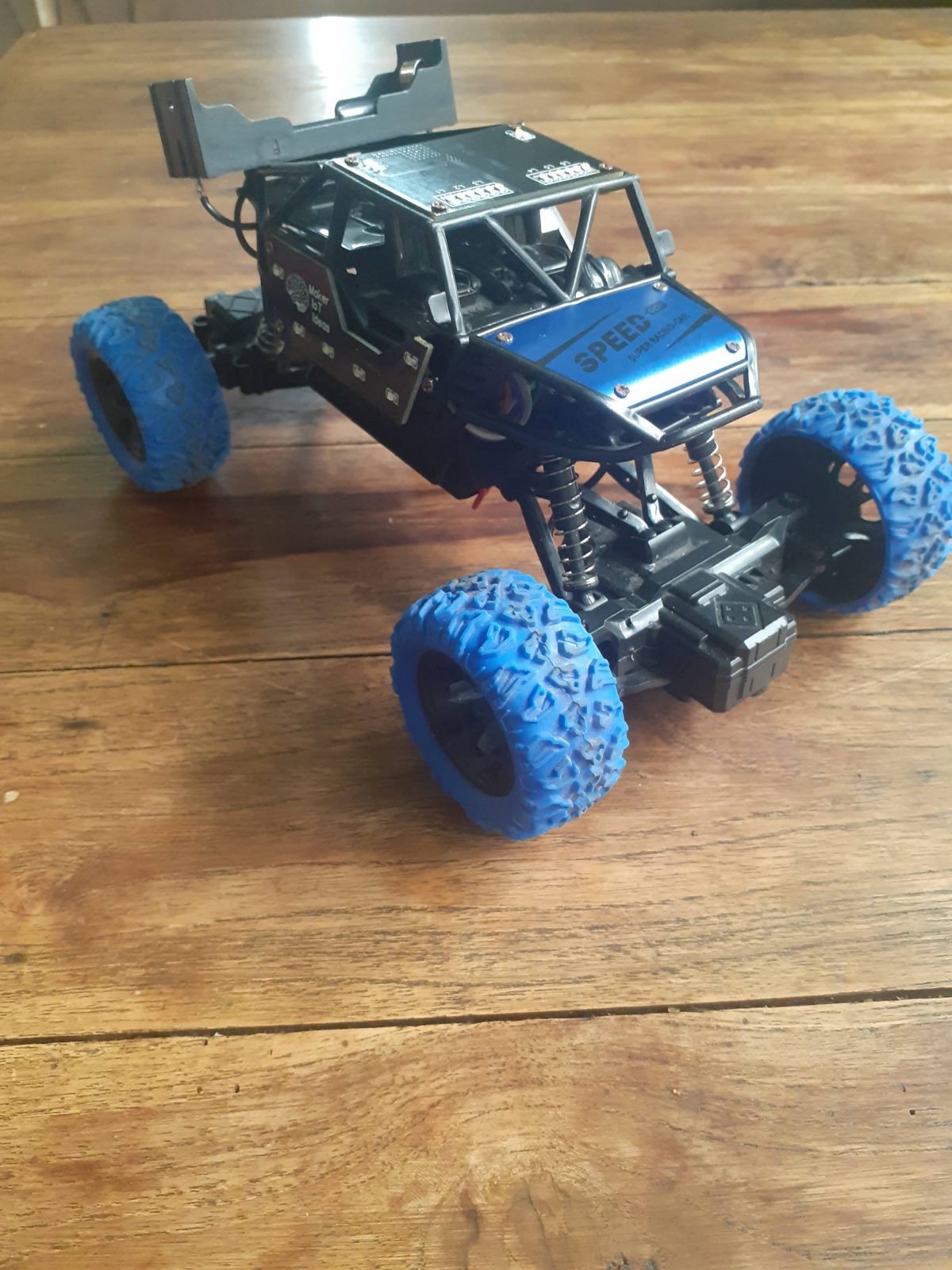
The “almost completed ” Robotic Toy Car
With the completion of the side-panels, it was also time to start work on the power wiring and other essential components of the project, which will get their own detailed post in a few days.

Some details on the construction:
The toy originally came with a single 500mA 14500 cell, which unfortunately stopped working very soon after only a few uses… This was however one of the reasons why the entire project happened in the first place, so no complaints there.
I decided to replace it with a 18560 cell with a capacity of about 1900mA. This cell is much bigger however, and I had to think of where to place it. I decided to put it on the roof, sort of emulating a “spoiler”.
Some of the next parts of the project will be the remote control unit, which will basically be an ESP8266 running ESP-Now protocol, as well as a decent battery charging and power distribution circuit, that will protect the Lipo cell from over charging and discharging, as well as provide sufficient power for all the added electronics in the toy car.
“But you said it was Robotic, so why have a remote control?”
The initial plan for the project did indeed say robotic, but it is also designed to be a learning platform, especially to teach coding. With that in mind, it is definitely better to keep things simple for now, and add sensors and more capabilities later on, especially as I am actually planning to replace the main MCU board with a more powerful ESP32 in a next version anyway.
The car body is also extremely cramped, and does not have any space for mounting sensors at all. I plan to remedy that by designing and 3d-printing a whole new custom body shell later… providing that my young friend actually stays interested enough to learn the coding… If he doesn’t, he will as least have a very interesting looking custom remote controlled toy car.
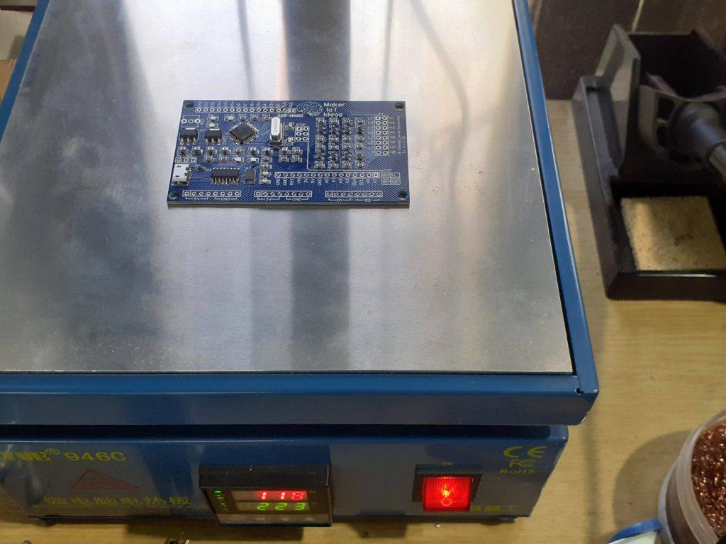
Manufacturing the PCB
The PCB for this project is currently on its way from China, after having been manufactured at PCBWay.
Please consider supporting them if you would like your own copy of this PCB, or if you have any PCB of your own that you need to be manufactured.

If you would like to have PCBWAY manufacture one of your own, designs, or even this particular PCB, you need to do the following…
1) Click on this link
2) Create an account if you have not already got one of your own.
If you use the link above, you will also instantly receive a $5USD coupon, which you can use on your first or any other order later. (Disclaimer: I will earn a small referral fee from PCBWay. This referral fee will not affect the cost of your order, nor will you pay any part thereof.)
3) Once you have gone to their website, and created an account, or login with your existing account,

4) Click on PCB Instant Quote

5) If you do not have any very special requirements for your PCB, click on Quick-order PCB

6) Click on Add Gerber File, and select your Gerber file(s) from your computer. Most of your PCB details will now be automatically selected, leaving you to only select the solder mask and silk-screen colour, as well as to remove the order number or not. You can of course fine-tune everything exactly as you want as well.


7) You can also select whether you want an SMD stencil, or have the board assembled after manufacturing. Please note that the assembly service, as well as the cost of your components, ARE NOT included in the initial quoted price. ( The quote will update depending on what options you select ).

8) When you are happy with the options that you have selected, you can click on the Save to Cart Button. From here on, you can go to the top of the screen, click on Cart, make any payment(s) or use any coupons that you have in your account.
Then just sit back and wait for your new PCB to be delivered to your door via the shipping company that you have selected during checkout.