
In August of 2021, MakerIoT2020 released the MCU-8266-12E IoT Controller PCB, (part 1 is available here in case you missed that). Shortly after that, we started working on an expansion add-on card, that would work with the APE (Arduino Port Expander) protocol in ESPHome.
While I could have used a standard Arduino board for this, and in fact, I have done so during many of the testing stages,
I decided to design a custom PCB specifically for this task, in order to achieve two specific things…
1). The standard Arduino Board comes in either a 5v logic or 3v logic device. While this is perfect for many projects,
it is still sometimes required to use a logic level converter with some sensors and devices. LORA is a good example of that. As I really dislike using a breadboard, due to their inherent unreliable connections and the ever-present mess of wires going everywhere, I wanted an Arduino or ATMEGA328 based device that already has a level converter built-in.
As I could not find anything like that for sale, I decided to build my own, as you will see shortly.
2). I wanted to start moving away from using the Arduino IDE as much as possible. While the Arduino IDE is great for most tasks, It does lack in a few areas. I thus want to slowly ease myself back into using AVR C, and that requires a board that can be flashed via ICSP. ( yes, yes, you can flash an Arduino with ICSP as well. ) In the case of the planned expansion card, it would basically be a device that is flashed once and then left alone. Serial flashing would be quite unnecessary on there anyway.
The other reason, still part of point 2, is that it seems like everyone else is having all sorts of problems with fuses on the ATMega328 on custom boards etc… I wanted to see if that is really the case or not…
The PCB should also be useable as a standard “Arduino” type device to assist in prototyping and development.
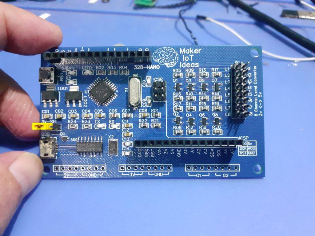
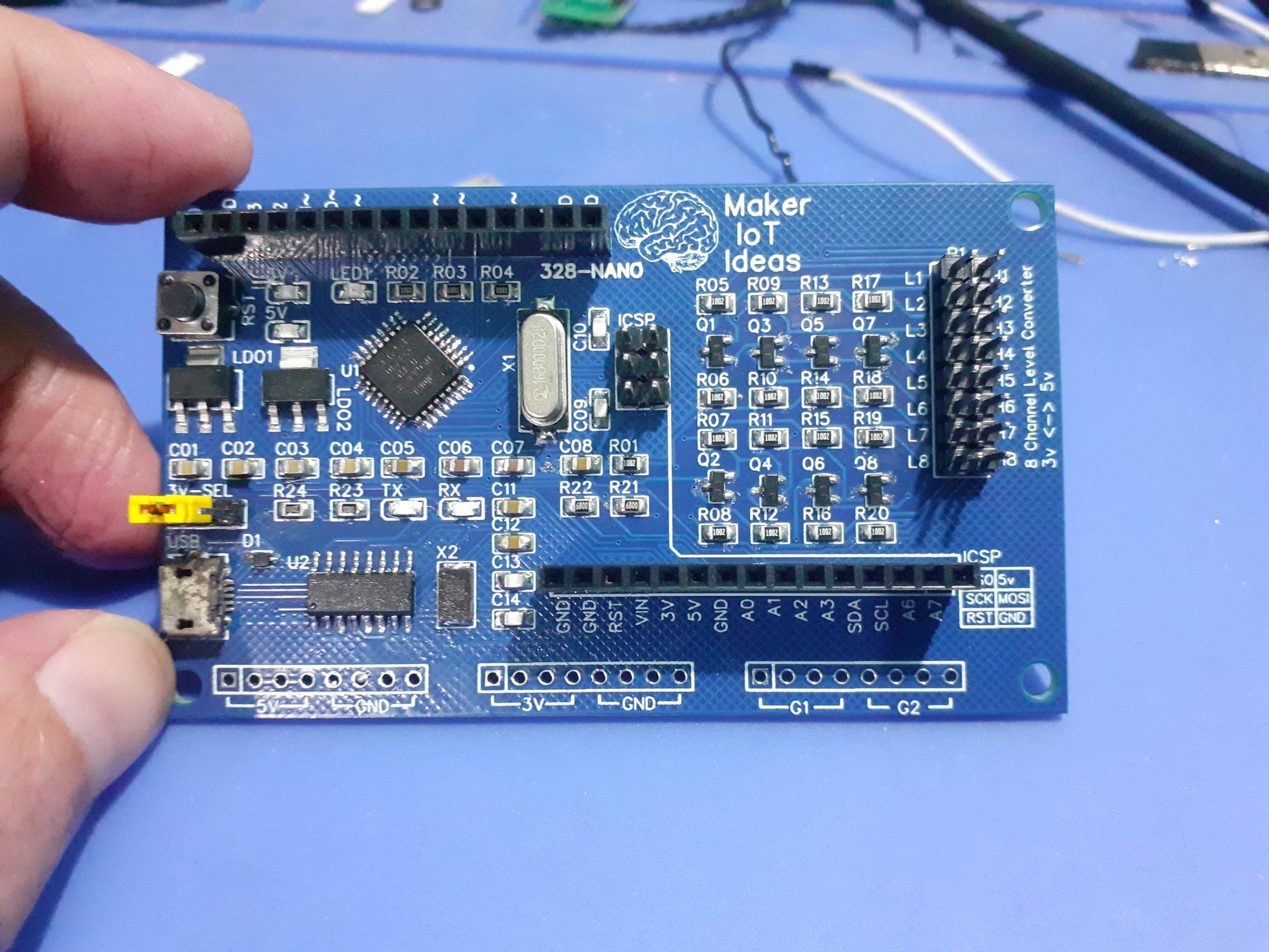
a Quick description of the PCB:
Standard Arduino type headers and pins are provided, with pin labels as for the Arduino Nano.
This gives us:
ATMega 328P MCU running at 16Mhz
12 Digital IO (D2 to D13) [ 14 if we use D1 and D2 as well ]
8 Analog Inputs (A0 to A7) [ A4 and A5 are used for I2C ]
ICSP header for uploading code
USB Port with CH340G for Arduino style serial flashing [This will be removed on the next version]
A Dedicated LDO 3.3v Voltage regulator, with a selectable input source (5v from USB, or directly from VIN – for high current use applications – MAX of 800mA)
An 8 Channel Bi-Directional Logic Level Converter, for now, the converter is fixed at bi-directional 3v to 5v conversion.
Additional 5v (x4), 3v (x4) and Ground pins (x8), as well as 2 general use bus connections (G1, G2) which I added for use with I2C
Led’s are provided on 5v, 3v, Serial Rx, Tx, as well as on pin D13.
Dimensions: 86mm x 51mm
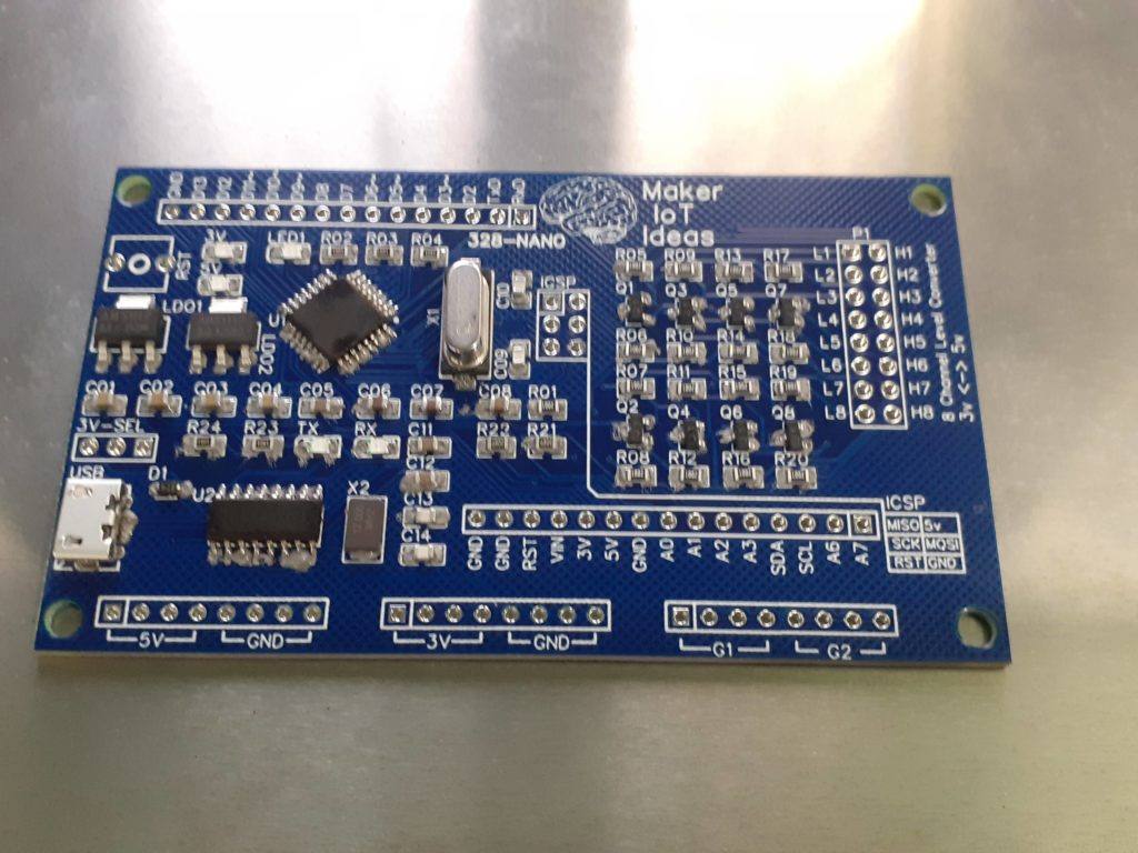
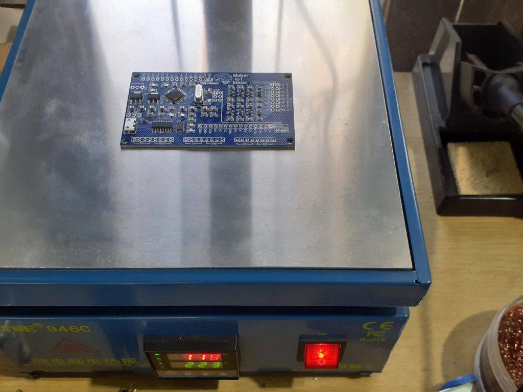
Manufacturing the PCB
This PCB was manufactured at PCBWAY. The Gerber files and BOM, as well as all the schematics, will soon be available as a shared project on their website. If you would like to have PCBWAY manufacture one of your own, designs, or even this particular PCB, you need to do the following…
1) Click on this link
2) Create an account if you have not already got one of your own.
If you use the link above, you will also instantly receive a $5USD coupon, which you can use on your first or any other order later. (Disclaimer: I will earn a small referral fee from PCBWay. This referral fee will not affect the cost of your order, nor will you pay any part thereof.)
3) Once you have gone to their website, and created an account, or login with your existing account,

4) Click on PCB Instant Quote

5) If you do not have any very special requirements for your PCB, click on Quick-order PCB
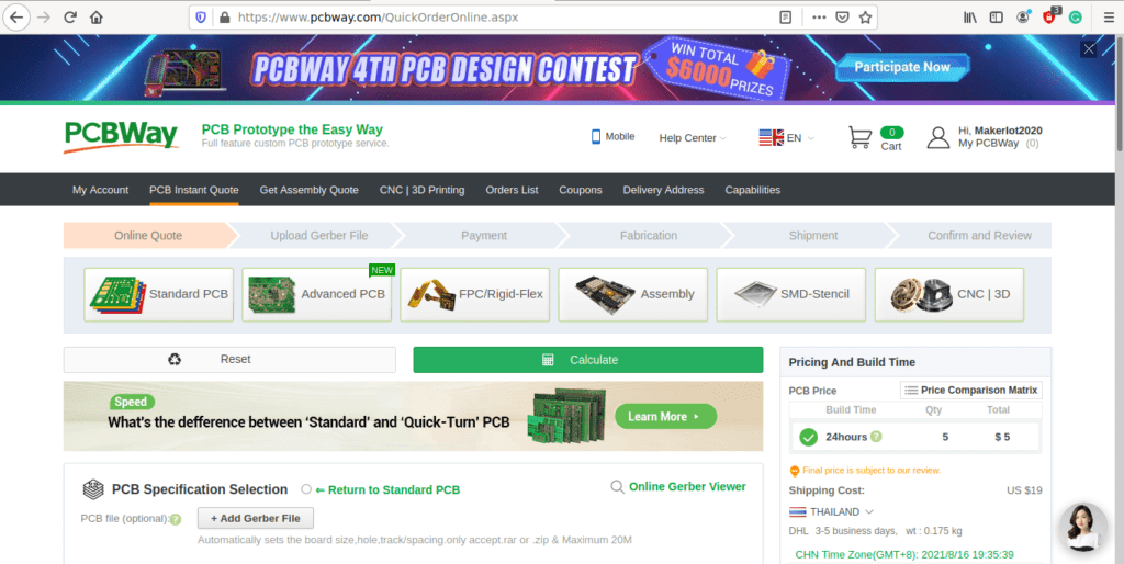
6) Click on Add Gerber File, and select your Gerber file(s) from your computer. Most of your PCB details will now be automatically selected, leaving you to only select the solder mask and silk-screen colour, as well as to remove the order number or not. You can of course fine-tune everything exactly as you want as well.


7) You can also select whether you want an SMD stencil, or have the board assembled after manufacturing. Please note that the assembly service, as well as the cost of your components, ARE NOT included in the initial quoted price. ( The quote will update depending on what options you select ).
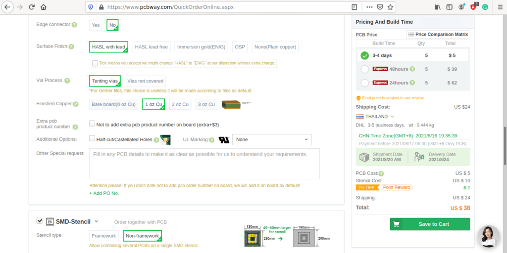

8) When you are happy with the options that you have selected, you can click on the Save to Cart Button. From here on, you can go to the top of the screen, click on Cart, make any payment(s) or use any coupons that you have in your account.
Then just sit back and wait for your new PCB to be delivered to your door via the shipping company that you have selected during checkout.
Conclusion
In conclusion, the PCB works quite well, with no issues with flashing the ATMEGA328P with an ICSP programmer from the Arduino IDE, as well as via USB from the Arduino IDE.
The level converter works as expected, successfully translating bidirectional signals on I2C and SPI to and from 3v and 5v devices.
In the next stage, we will focus on the stock APE protocol sketch, as provided by ESPHome, and then, once that is working perfectly, modify it to suit our needs.