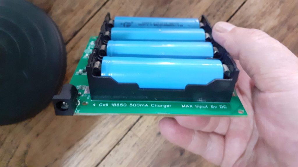
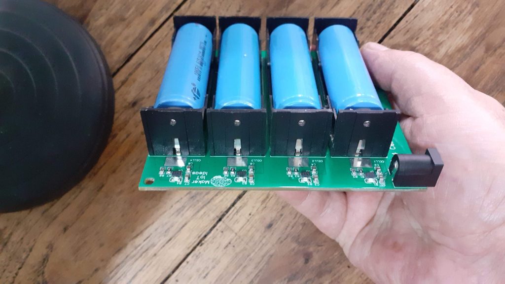
Simple Smart Light Controller

Adding a bit of automation to a certain area of the house can definitely help with saving energy. With this Simple Smart Light Controller, I aimed to do just that… Let me give you a tiny bit of context… Houses in SE Asia are built to some “questionable” standards and designs, and electrical installations are usually even more suspect… Our house is no exception. Being a rental, I do not want to go and make changes unless things are outright dangerous… Kitchens are usually a mixture of inside/outside areas, and this is where my device fits in…

The light in the outside kitchen consists of a simple bulb that the owner has routed into the house via an electrical flex cord, at least that was standard… But, due to laziness or just whatever, that cord was never terminated into a proper switch… He just added a plug. This is thus my opportunity to make life a bit easier for myself in that area. I could have opted for a standard switch, but then, automating this can take care of another problem… We constantly forget to switch that light off, as the plug is in a “strange place” that is not usually associated with the kitchen lights…
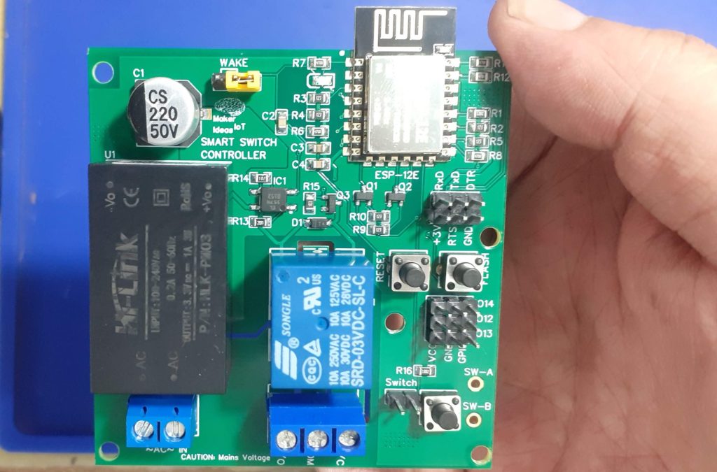

What I have thus come up with is a simple ESP8266-based solution with a single relay ( optically isolated from the board), as well as a few additional GPIO pins, just in case I want to hang some additional sensors onto this in the future.

The device should also be powered directly from the mains, as adding another external AC to DC adapter would definitely NOT do at all!

What is on the PCB
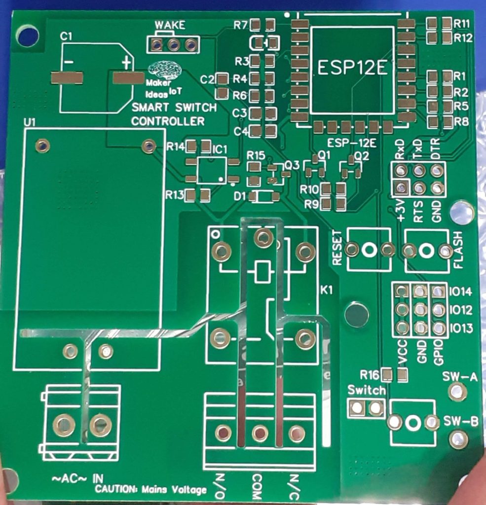

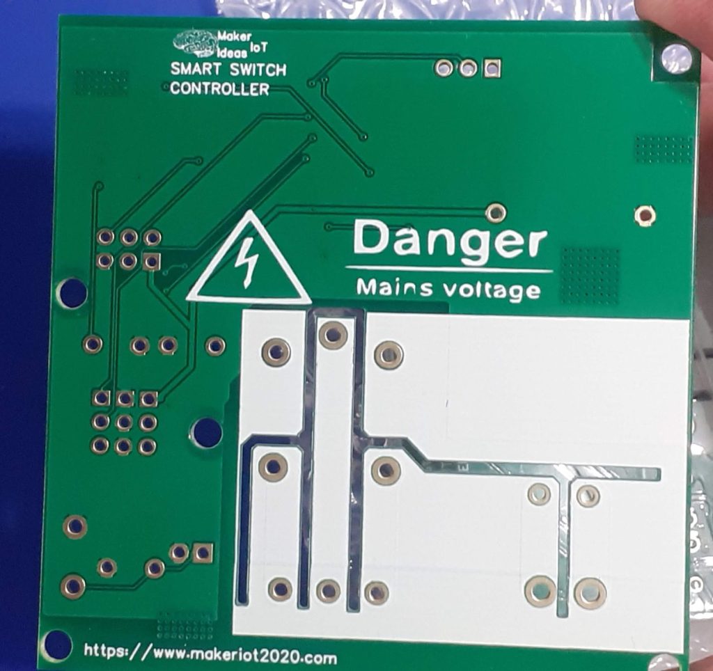
Lets look at the empty PCB, in order to understand better what is where on the board.

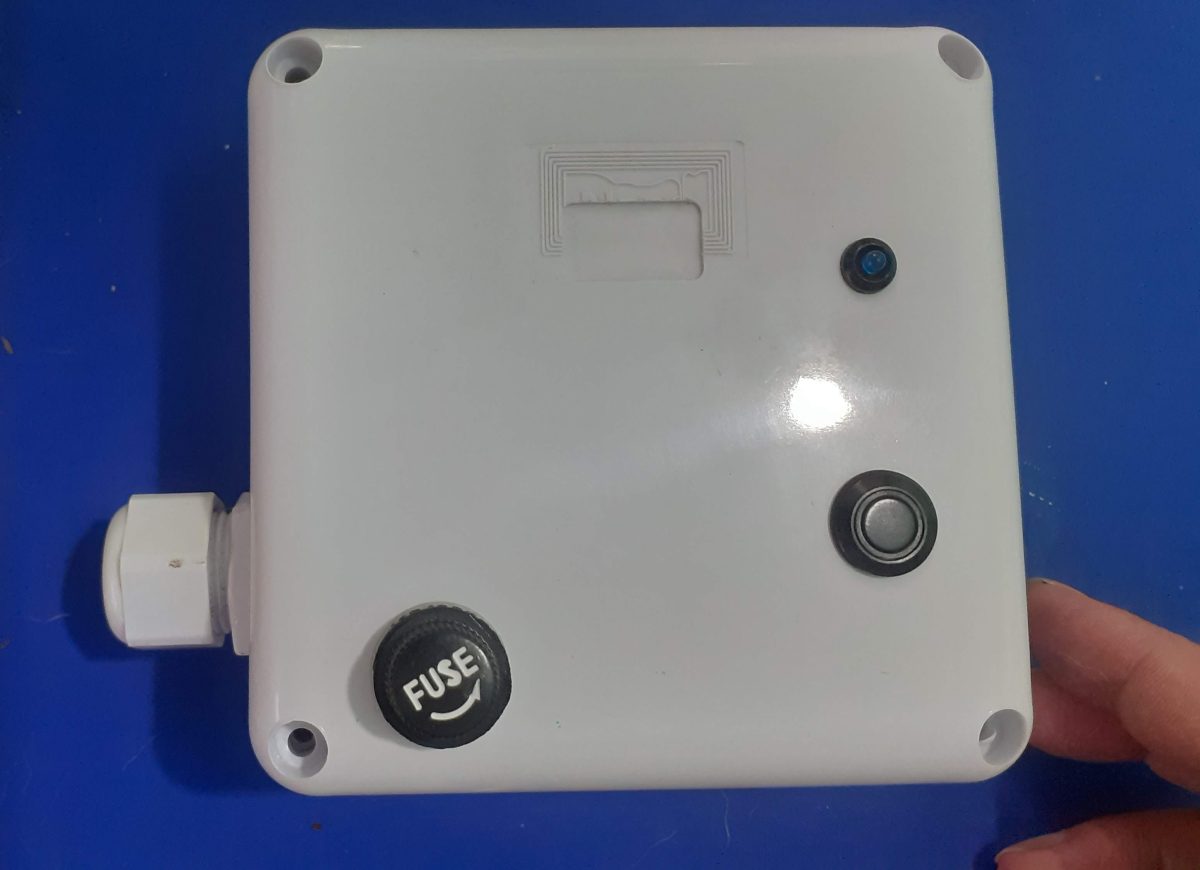
Starting on the Left Side, at the bottom corner, we have our mains voltage input, 220V or 110V, depending on where you live. That goes directly into U1, which is a AC-to-DC converter, providing 3.3v at 1A to the board. Note that I did not place a fuse directly on the board. I prefer to have an inline fuse on the line, which is also accessible from the enclosure.

A series of cutouts on the PCB provides additional mains isolation and also prevents mains voltage tracking towards other tracks in the event of a fault.
The Mains area also does not have a copper pour.

In the top left corner, towards the center, is a WAKE jumper. This is connected to GPIO16 and can be used to wake the ESP8266 from “deep sleep” if configured in the firmware.

Relay K1, and its screw terminal connector is in the bottom center of the board, with the relay contacts clearly labelled.

On the right of the PCB, we have the programming header, complete with Auto Flash and Reset circuitry, as well as manual Flash and Reset Buttons below that.

A 3×3 header connector follows, with access to 3.3v, Ground as well as 3 additional GPIO pins for other applications.

Finally, we have the relay control switch, with a few options to connect external switches, either on the 2.54mm header, or via wires soldered to the pads marked SW-A and SW-B


The populated PCB will thus make more sense if we look at the picture above now since we had a detailed look at it above…


The Schematic is made available at the link above.

Configuration and Software

This build was designed with ESPHome in mind, so we will focus on that there.
You can however very easily use standard Arduino/ESP8266 code to control this as well…

The YAML configuration for the device will be as follows: (note that this is quite simplified, as I am still fine-tuning the actual features that I require)

esphome:
  name: smart-switch-01
  friendly_name: SMART-SWITCH-01

esp8266:
  board: nodemcuv2
  restore_from_flash: true

# Enable logging
logger:

# Enable Home Assistant API
api:
  encryption:
    key: "hfYNn8KSbVq26rGkPOJo4yLj/d/WY7Hk0H3TmxlWZAU="

ota:
  password: "85ed2a8afcd61d0f4c65db7b92bdacc5"

wifi:
  ssid: !secret wifi_ssid
  password: !secret wifi_password

  # Enable fallback hotspot (captive portal) in case wifi connection fails
  ap:
    ssid: "Smart-Switch-01 Fallback Hotspot"
    password: "XovAx4n1H1qT"

captive_portal:

text_sensor:
  - platform: wifi_info
    ip_address:
      name: IP Address
    ssid:
      name: SSID
    bssid:
      name: BSSID
    mac_address:
      name: Wifi MAC
    scan_results:
      name: WiFi Scan Results


sensor:
  - platform: adc
    pin: VCC
    name: "ESP8266 Chip Voltage"
    id: mcu_voltage
    unit_of_measurement: "V"
    device_class: "voltage"
    accuracy_decimals: 2
    update_interval: 60s
    entity_category: "diagnostic"
    
  - platform: wifi_signal
    name: "WiFi Signal Sensor"
    id: wifi_strength
    device_class: "signal_strength"
    unit_of_measurement: "dBm"
    update_interval: 240s
    entity_category: "diagnostic"

  - platform: copy # Reports the WiFi signal strength in %
    source_id: wifi_strength
    name: "WiFi Signal Strength"
    filters:
      - lambda: return min(max(2 * (x + 100.0), 0.0), 100.0);
    unit_of_measurement: "%"
    entity_category: "diagnostic"


light:
 # - platform: status_led
 #   pin: GPIO13
 #   id: status_indicator
 #   name: "ID Light"
    
  - platform: binary
    name: "Kitchen Outside Light"
    output: relay_01
    id: kitchen_light
    on_turn_on:
    - light.turn_on:
        id: slow_light
        effect: "Slow Pulse"
    

    on_turn_off:
    - light.turn_off: slow_light
    

  - platform: monochromatic
    id: slow_light
    output: light_status
    restore_mode: RESTORE_AND_OFF
    effects:
      - pulse:
          name: "Slow Pulse"
          # transition_length: 1s      # defaults to 1s
          update_interval: 2s

binary_sensor:
  - platform: gpio
    pin:
      number: GPIO5
      mode:
        input: true
        pullup: true
    id: kitchen_light_toggle
    filters:
      - delayed_on: 200ms
      - delayed_off: 200ms
    on_press:
      then:
        - light.toggle: kitchen_light
  - platform: status
    name: "Kitchen Light Controller"
     
switch:
  - platform: restart
    name: "Restart Device"

# Relay output
output:
  - platform: gpio
    id: relay_01
    pin: GPIO4
    inverted: true
  - platform: esp8266_pwm
    id: light_status
    pin: GPIO12
 

Manufacturing the PCB

I choose PCBWay for my PCB manufacturing. Why? What makes them different from the rest?

PCBWay‘s business goal is to be the most professional PCB manufacturer for prototyping and low-volume production work in the world. With more than a decade in the business, they are committed to meeting the needs of their customers from different industries in terms of quality, delivery, cost-effectiveness and any other demanding requests. As one of the most experienced PCB manufacturers and SMT Assemblers in China, they pride themselves to be our (the Makers) best business partners, as well as good friends in every aspect of our PCB manufacturing needs. They strive to make our R&D work easy and hassle-free.

How do they do that?

PCBWay is NOT a broker. That means that they do all manufacturing and assembly themselves, cutting out all the middlemen, and saving us money.

PCBWay’s online quoting system gives a very detailed and accurate picture of all costs upfront, including components and assembly costs. This saves a lot of time and hassle.

PCBWay gives you one-on-one customer support, that answers you in 5 minutes ( from the Website chat ), or by email within a few hours ( from your personal account manager). Issues are really resolved very quickly, not that there are many anyway, but, as we are all human, it is nice to know that when a gremlin rears its head, you have someone to talk to that will do his/her best to resolve your issue as soon as possible.

Find out more here

Assembly and Testing

This device does not need a stencil for assembly, but using one will definitely speed up things. I chose to do this build all by hand, from applying solder-paste, up to placing components.

Soldering was done on a hotplate, as usual, to reflow everything at the same time. TH components were then placed and hand-soldered.

Uploading the initial firmware, after adding the device to ESPHome was done with an external USB-to-UART converter. All further firmware changes were made via OTA.

Enclosure and some of the wiring

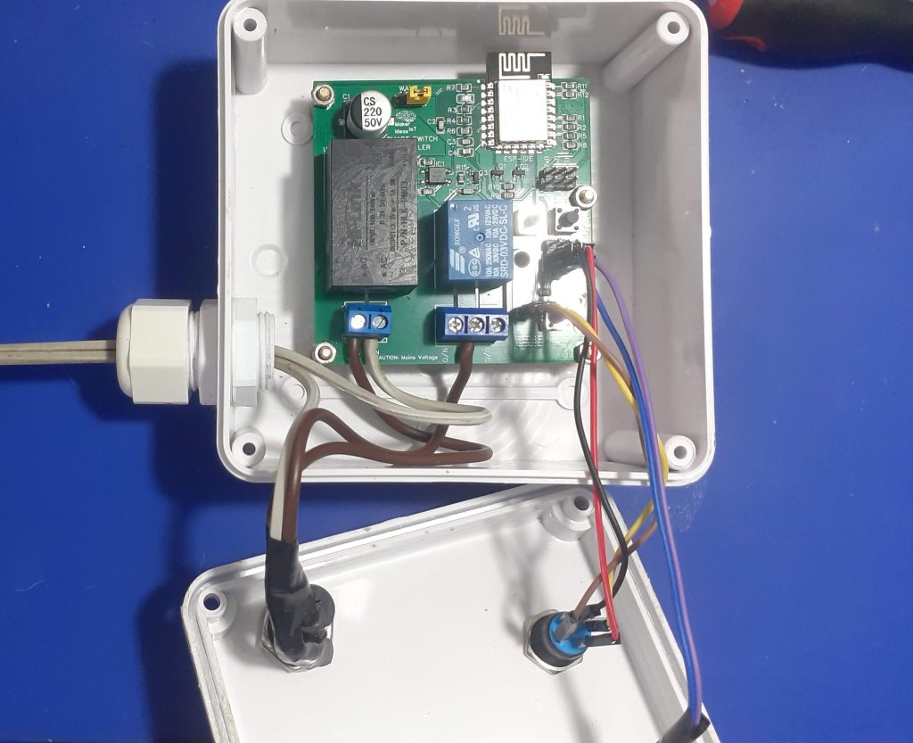
It is important to mention here that this PCB is powered by mains voltage. I chose to use an inline fuse, BEFORE the connector on the PCB. It is also notable that the relay common is connected to the live wire, BEFORE the fuse, as the lightbulb acts as its own fuse – it blows when a fault occurs.

The Lightbulb neutral will be connected to the circuit breaker, together with the device live and neutral.

This way, the fuse only acts on the actual device, and I can use a lower-rating fuse, since I do not have to accommodate the current from the lightbulb as well…

Summary

The device works as planned, with no problems…
Below is some pictures from it in Home Assistant

LED COB Controller

COB LED lights, or Chip-on-Board LED lights, are a type of LED light that has all of the LED chips mounted on a single substrate. This makes them more efficient than traditional LED lights, which have individual LED chips mounted on a circuit board. COB LED lights also produce a more uniform light output, and they can be used in a wider variety of applications.

Here are some of the benefits of using LED COB lights:

  • are very efficient, and they can produce up to 100 lumens per watt. This means that they use less energy than traditional light bulbs, and they can save you money on your energy bills.
  • produce a more uniform light output than traditional LED lights. This means that they do not create hot spots or shadows, and they provide a more comfortable light to work under.
  • are very durable, and they can last for many years. They are not as susceptible to damage from heat or vibration as traditional light bulbs, and they can withstand harsh conditions.
  • can be used in a wide variety of applications, including indoor and outdoor lighting, commercial and residential lighting, and automotive lighting.

They can however be quite a pain to power in a traditional 110v/220v AC wired house or workshop, as some of them actually required DC current to work.
I have decided to use a pair of them to provide additional, dimmable light at my electronics workbench, a place where extra light is sometimes a very necessary commodity. The ability to dim the lights will definitely aid in many scenarios as well.

Variable voltage Power Module
The Variable voltage Power module was designed specifically for this project


The project consists of two main parts, the first being the Variable Voltage Power Module, which I published a few days ago. The particular COB lights that I will be using, were scavenged from a battery-operated emergency light panel, which had some problems which were not economical to repair. The light modules themselves, however, looked good and were perfectly working as well.
The only issue was that they were 6v DC. So using straight 12v there was out of the question. 6V being an odd voltage in my lab, I designed the module above specifically to provide that.

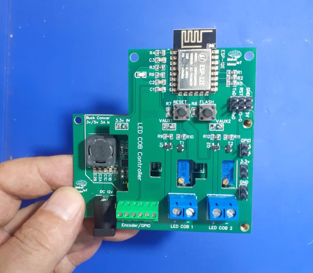
LED COB Controller stacked on top of Variable Voltage Poser Module


The second part of the project consists of a simple Custom ESP-12E PCB. Why ESP12-E? Well, I have a lot of them lying in stock, and since I won’t need any advanced features, commonly found on the bigger ESP32s, I decided to design around something that I have in stock, rather than overcomplicate the design with a bigger more advanced chip. The project features a rotary encoder, to adjust light intensity, as well as push buttons to toggle the lights on or off…

All of this is of course controlled with ESPHome. This choice gives me the option of manual or fully automatic control from HomeAssistant. It also saves me a lot of coding, as everything usually just works.

What is on the PCB?

We shall focus mainly on LED COB Controller PCB.
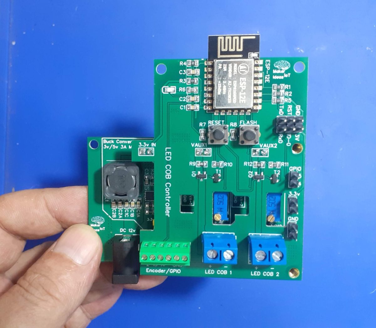
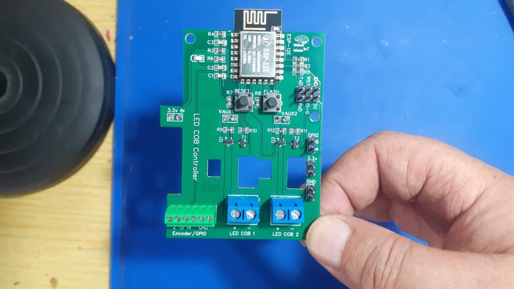
In order to understand everything, please refer to the picture below:

LED COB controller without Power Module

The board consists of a few sections, which can be divided as follows:

ESP-12E (8266) supporting circuitry

The top area is mainly the supporting circuitry for the ESP-12E, which includes a 6-pin header to flash firmware, the classic ESP32/8266 Auto Flash/Reset circuit, and manual Flash and Reset switches. Note that the board DOES NOT contain any USB-to-Serial circuitry. I usually use those only once or twice, and update firmware OTA after that. Using an external USB-to-Serial adapter is thus sufficient for my purposes.

Power and LED Control circuitry

Power enters the board in the center, using header pins mounted on the bottom of the PCB. From left to right, these are 3.3v and then two variable voltage inputs. These all originate from the Variable voltage Power Module, mounted below the main PCB. The LED Control circuitry consists of two P-Channel Mosfets, the configuration of which was previously tested in another project, the “P-MOS MOSFET Driver Board“, also published a few weeks ago. The SI2301 P-Channel Logic Level MOSFET, used here is capable of switching up to 2.3A at 20v, and thus more than capable of handling the 300mA that the LED COB modules require.

Four cutouts are provided to access test points on the power module below, as well as the potentiometers used to set the voltage that will ultimately be sent to the LED COB Modules.

Wide copper traces connect the Mosfet’s to Screw Terminals for the LED Modules.

The Final part of the PCB is dedicated to control interfaces. A single 6-way screw terminal is provided at the bottom left corner, this is used to connect a rotary encoder, or give direct access to additional GPIO pins. On the Right hand side of the PCB, a series of header pins give access to additional 3.3v and ground connections, in addition to GPIO 4 and 5, which is usually used for I2C…

LED COB Controller stacked on top of Variable Voltage Poser Module

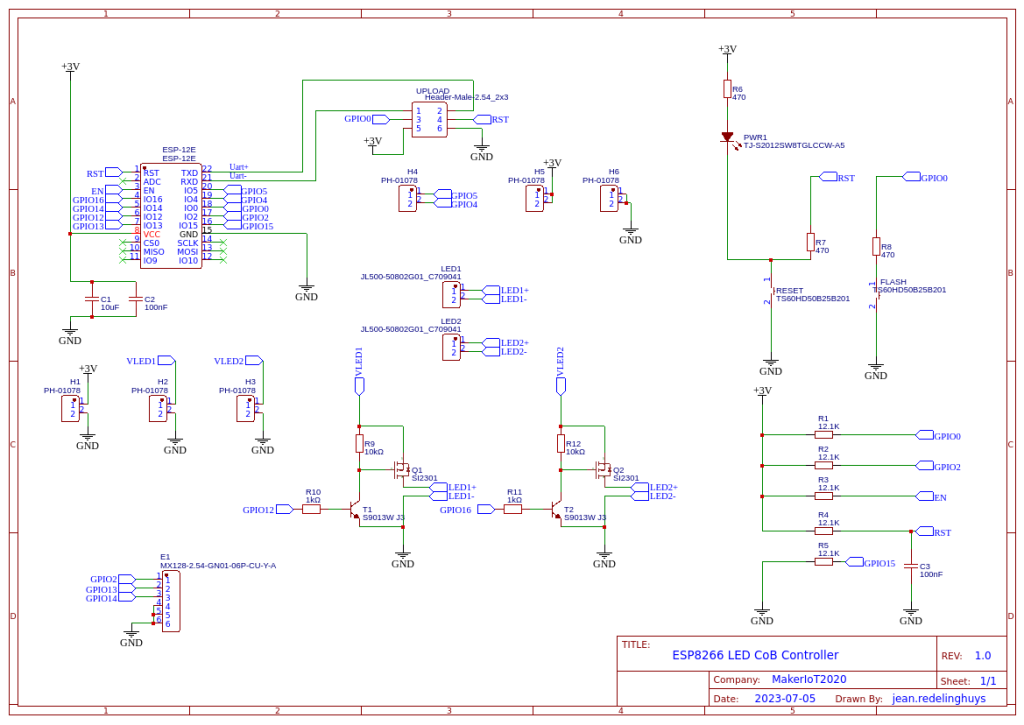
The Schematic

Configuration and Software

As mentioned above, this device was designed to be used with ESPHome. The configuration is thus a single YAML file and can be greatly customised to suit your exact needs…

With that in mind, I present here a VERY basic YAML file, that will toggle the LED lights on or off on pressing the encoder switch, as well as adjust the brightness by turning the encoder.

esphome:
  name: led-cob-controller
  friendly_name: LED_COB-Controller

esp8266:
  board: nodemcuv2
  restore_from_flash: True

# Enable logging
logger:

# Enable Home Assistant API
api:
  encryption:
    key: "<esphome generated>"

ota:
  password: "<esphome generated>"

wifi:
  ssid: !secret wifi_ssid
  password: !secret wifi_password

  # Enable fallback hotspot (captive portal) in case wifi connection fails
  ap:
    ssid: "Led-Cob-Controller"
    password: "<your recovery password here>"

captive_portal:

# I suggest you only copy paste from here on downwards.
# Setup the default device in ESPHome, and when it is available,
# come back and add the commands below here


text_sensor:
  - platform: wifi_info
    ip_address:
      name: IP Address
    ssid:
      name: SSID
    bssid:
      name: BSSID
    mac_address:
      name: Wifi MAC
    scan_results:
      name: WiFi Scan Results


sensor:
  - platform: adc
    pin: VCC
    name: "ESP8266 Chip Voltage"
    id: mcu_voltage
    unit_of_measurement: "V"
    device_class: "voltage"
    accuracy_decimals: 2
    update_interval: 60s
    entity_category: "diagnostic"
    
  - platform: wifi_signal
    name: "WiFi Signal Sensor"
    id: wifi_strength
    device_class: "signal_strength"
    unit_of_measurement: "dBm"
    update_interval: 240s
    entity_category: "diagnostic"

  - platform: copy # Reports the WiFi signal strength in %
    source_id: wifi_strength
    name: "WiFi Signal Strength"
    filters:
      - lambda: return min(max(2 * (x + 100.0), 0.0), 100.0);
    unit_of_measurement: "%"
    entity_category: "diagnostic"

  - platform: copy
    source_id: rcbright
    name: "LED Light Brightness"
    unit_of_measurement: "%"
    filters:
      - lambda: return (x * 100);

  - platform: rotary_encoder
    name: "Brightness Control"
    id: rcbright
    min_value: 0.00
    max_value: 100.00
    publish_initial_value: True
    restore_mode: RESTORE_DEFAULT_ZERO

    pin_a: 
      number: GPIO13
      inverted: True
      mode:
        input: True
        pullup: True
      
    pin_b: 
      number: GPIO2
      inverted: True
      mode: 
        input: True
        pullup: True

    resolution: 1
    accuracy_decimals: 2
    filters:
    - lambda: return x / 100 ;
    on_clockwise:
    - light.control:
        id: led_light1
        brightness: !lambda |-
          // output value must be in range 0 - 1.0
          return id(rcbright).state ; // /100.0;
    - light.control:
        id: led_light2
        brightness: !lambda |-
          // output value must be in range 0 - 1.0
          return id(rcbright).state ; // /100.0;
    on_anticlockwise:
    - light.control:
        id: led_light1
        brightness: !lambda |-
          return id(rcbright).state ;   
    - light.control:
        id: led_light2
        brightness: !lambda |-
          // output value must be in range 0 - 1.0
          return id(rcbright).state ; // /100.0;  

binary_sensor:
  - platform: gpio
    pin: GPIO14
    id: light_switch
    name: "Light Switch"
    device_class: light
    on_click:
      then:
        - light.toggle: led_light1
        - light.toggle: led_light2
    

light:
  - platform: monochromatic
    name: "LED1_LIGHT_TEST"
    id: led_light1
    output: output_component1
  - platform: monochromatic
    name: "LED2_LIGHT_TEST"
    id: led_light2
    output: output_component2

# Example output entry
output:
  - platform: esp8266_pwm
    id: output_component1
    pin: GPIO12
  - platform: esp8266_pwm
    id: output_component2
    pin: GPIO16

Manufacturing the PCB

I choose PCBWay for my PCB manufacturing. Why? What makes them different from the rest?

PCBWay‘s business goal is to be the most professional PCB manufacturer for prototyping and low-volume production work in the world. With more than a decade in the business, they are committed to meeting the needs of their customers from different industries in terms of quality, delivery, cost-effectiveness and any other demanding requests. As one of the most experienced PCB manufacturers and SMT Assemblers in China, they pride themselves to be our (the Makers) best business partners, as well as good friends in every aspect of our PCB manufacturing needs. They strive to make our R&D work easy and hassle-free.

How do they do that?

PCBWay is NOT a broker. That means that they do all manufacturing and assembly themselves, cutting out all the middlemen, and saving us money.

PCBWay’s online quoting system gives a very detailed and accurate picture of all costs upfront, including components and assembly costs. This saves a lot of time and hassle.

PCBWay gives you one-on-one customer support, that answers you in 5 minutes ( from the Website chat ), or by email within a few hours ( from your personal account manager). Issues are really resolved very quickly, not that there are many anyway, but, as we are all human, it is nice to know that when a gremlin rears its head, you have someone to talk to that will do his/her best to resolve your issue as soon as possible.

Find out more here

Assembly and Testing

This device does not need a stencil for assembly, but using one will definitely speed up things. I chose to do this build all by hand, from applying solder-paste, up to placing components.

Soldering was done on a hotplate, as usual, to reflow everything at the same time. TH components were then placed and hand-soldered.

Uploading the initial firmware, after adding the device to ESPHome was done with an external USB-to-UART converter. All further firmware changes were made via OTA.

The board performs well, with only slight heating of the LM317G variable voltage regulators on the power module when both LED COB modules are at 100% brightness. The current draw is within limits and seems to peak at about 600mA per COB…

Conclusion

This project took quite a while to move from idea to practical reality, mainly due to being busy with other more important stuff. In the end, I am happy that I sat down and did it, because it definitely will become a valuable tool in my work area.

Variable Voltage Power Module

Powering electronics projects are always challenging. This Variable voltage Power Module was designed to solve such a problem for a specific project that I am working on.

The ESP32 and their smaller cousin the ESP8266 are pretty well known for their high power requirements. Having used quite a few of these in various projects over the years, I wanted a power module that can supply me with enough current to keep these hungry little chips satisfied. I also needed variable voltages with more modest current capabilities, to drive LED COB modules for example.

The idea thus came to me to combine two recent projects, that I have been using together on the bench with great effect. These two are the Variable Breadboard Power Module, based on the LM317G, and the DC-DC Buck Converter that I designed a short time ago. Between these two devices, I can deliver up to 3A at 3v or 5v, or a variable voltage at up to 1.5A.

Let us take a look at what exactly was done here.

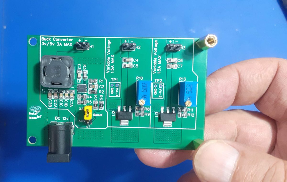
Variable Power Module

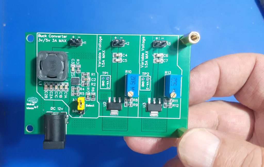
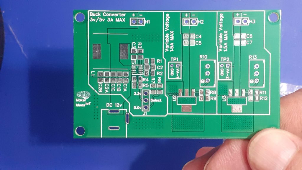
What is on the PCB?

The PCB consists of 3 independent power circuits, the first of which is a DC-to-DC Buck module, based on the MP9943 from MPS. This chip can source up to 3A at a preset voltage. In my case, I chose 3.3v and 5v, as I use those the most.

The second and third parts are a mirrored section, with the humble LM317G at their hearts. These are set up as variable voltage regulators, with their outputs adjustable via R10 and R13. These two can source two independent voltages, from about 1.0v right up to about 11.5v ( if VCC is 12V) at a respectable 1.5A or current.

All of this is powered by a single 12v Power supply. Note that the 12v supply should be capable of sourcing at least 3A of its own…

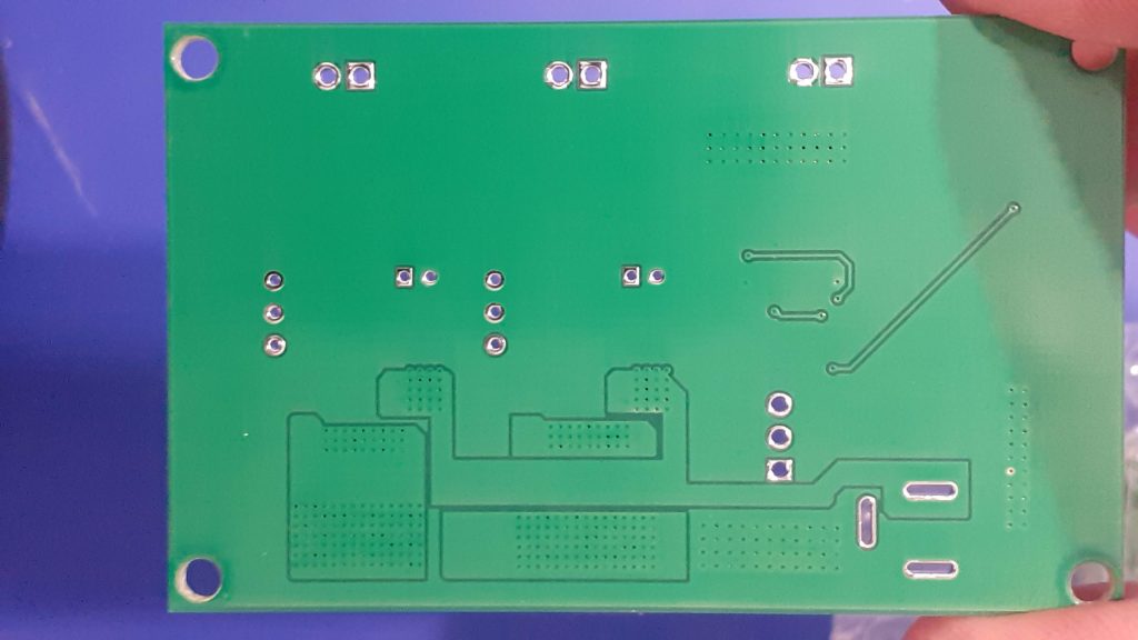
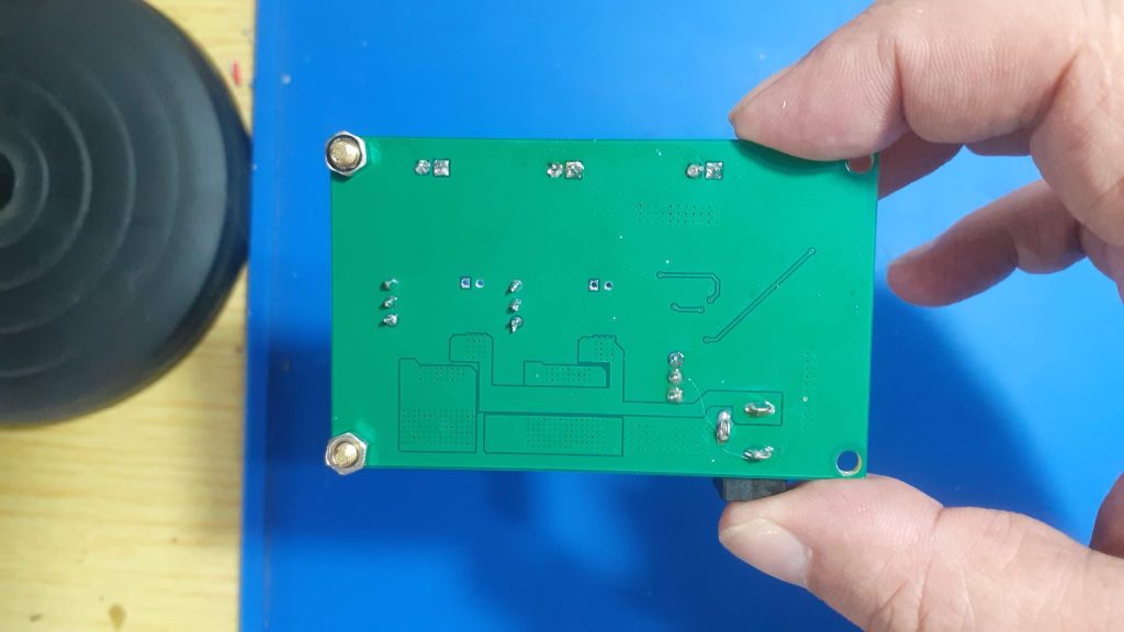
Variable voltage Power Module


The stepped-down voltages are provided via 3 2-way headers at the top of the PCB.

How do you use the board?

Using the module is easy. Power it from 12v DC ( or up to 24v if you really want to)

The 3.3v or 5v output is selected using jumper J1 ( Please switch the power off first, BEFORE you change this). The selected voltage will be available at H1

H2 and H3 provide variable voltages, that can be set using R10 for H2 and R13 for H3. Turning the potentiometer anti-clockwise will reduce the voltage, clockwise to increase.

Test points ( TP1 and TP2) can be probed with a multimeter while adjusting the voltages.

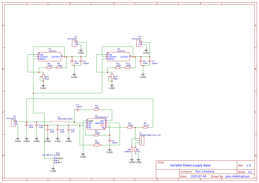
The Schematic

Manufacturing the PCB

I choose PCBWay for my PCB manufacturing. Why? What makes them different from the rest?

PCBWay‘s business goal is to be the most professional PCB manufacturer for prototyping and low-volume production work in the world. With more than a decade in the business, they are committed to meeting the needs of their customers from different industries in terms of quality, delivery, cost-effectiveness and any other demanding requests. As one of the most experienced PCB manufacturers and SMT Assemblers in China, they pride themselves to be our (the Makers) best business partners, as well as good friends in every aspect of our PCB manufacturing needs. They strive to make our R&D work easy and hassle-free.

How do they do that?

PCBWay is NOT a broker. That means that they do all manufacturing and assembly themselves, cutting out all the middlemen, and saving us money.

PCBWay’s online quoting system gives a very detailed and accurate picture of all costs upfront, including components and assembly costs. This saves a lot of time and hassle.

PCBWay gives you one-on-one customer support, that answers you in 5 minutes ( from the Website chat ), or by email within a few hours ( from your personal account manager). Issues are really resolved very quickly, not that there are many anyway, but, as we are all human, it is nice to know that when a gremlin rears its head, you have someone to talk to that will do his/her best to resolve your issue as soon as possible.

Find out more here

Assembly

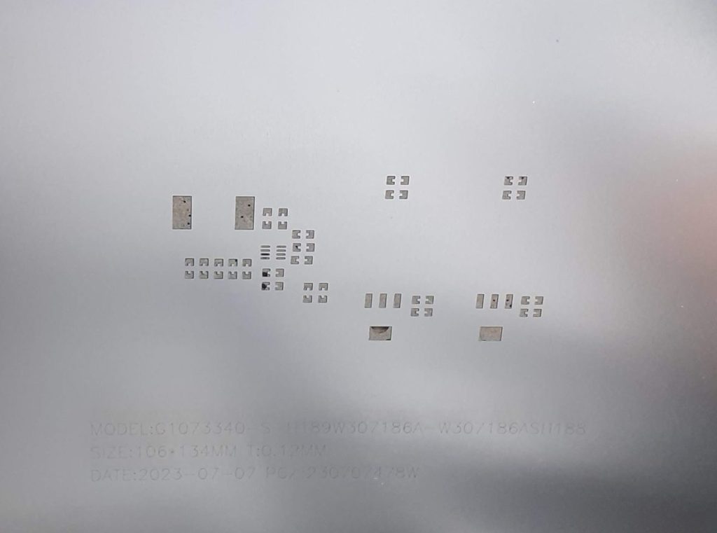
This PCB uses some very tiny components, so a stencil is highly recommended.


The Buck Converter IC is especially tiny.

Most of the other components can be soldered by hand, but I chose to do the entire assembly on a hotplate to reflow everything at the same time.

Testing


After assembly, I tested everything, measuring voltages with a multimeter, as well as adjusted H2 and H3 down to 6v, as I would be using the module on another project. I also tested the ripple on the Buck converter with an Oscilloscope, and it was well within the specs stated by the datasheet, at about +/- 100mV.

The entire module draws about 650mA at no load, and up to 3A when powering 2 6v LED COB modules and an ESP32 with I2S Audio modules connected as well.
Most of the current actually being drawn by the LM317G chips. The Buck converter is actually quite economical, drawing a modest 500mA at full load
( tested with a separate module that only contains a single buck converter module).

Conclusion

The power module works exactly as expected. It will perform well for its intended purpose, i.e powering an ESP12-E (8266) ESPHome device with two 6v LED COB modules in PWM mode, as well as an I2C display and various other sensors. In that application, I have successfully tested the entire project with a modest 12v at 1A wall-brick transformer, with no overheating or power shortage on any of the components. That is thus a win, in my books at least.

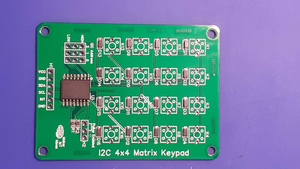
An I2C Matrix Keypad

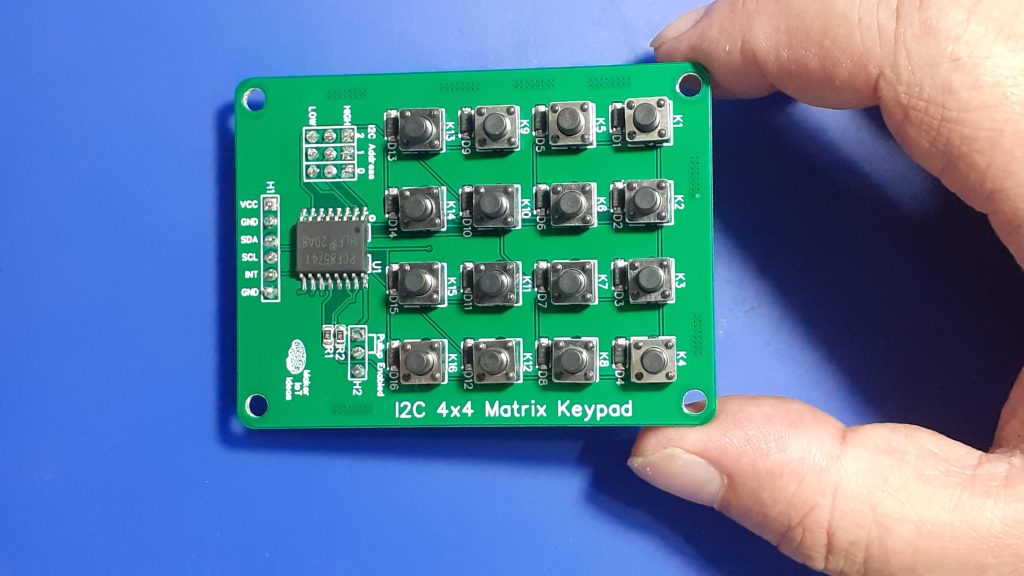
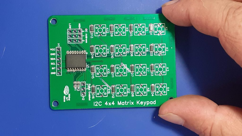
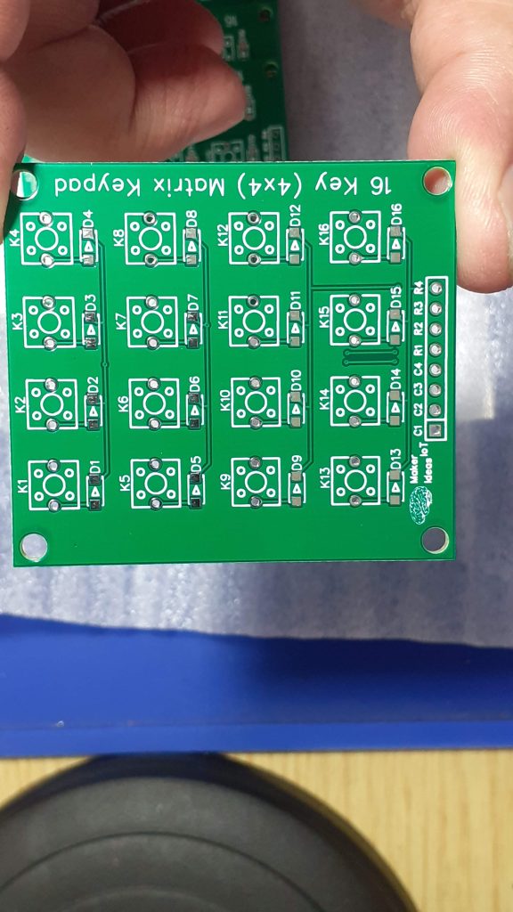
The completed I2C Matrix Keypad

In a previous post this month I introduced my 4×4 matrix keypad. That keypad was designed to be directly interfaced to a microcontroller’s GPIO pins or alternatively to an IO expander chip like the PCF8574. That design, while working very well had the problem of requiring 8 GPIO pins to function correctly.

GPIO pins on a microcontroller can be considered very precious resources, and it should then be logical to assume that we should find a way to use these GPIO pins in a more conservative way, to allow us to interface more peripherals.

I solved this problem by integrating the keypad with an IO Expander on the same PCB. That will allow us to get away with using only 2 GPIO pins, and also open up the option of adding more keypads to the I2C bus, in the event that we need that many keys for a particular project.

The Schematic

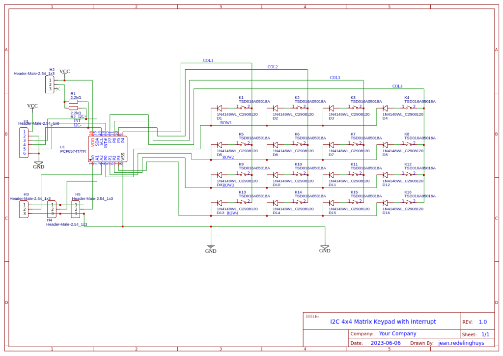
I2C 4×4 Matrix Keypad Schematic

Looking closely at the schematic, we can see that it is exactly the same basic keypad circuit that I used in the initial design. The only difference is that in this design, I have integrated a PCF8574 directly onto the PCB.

Some additional features include selectable I2C Pullup resistors ( usually my microcontroller development boards already include those) that can be activated with a jumper when needed. There are also a set of address selection jumpers, making it possible to stack keypads together into a bigger keyboard if you require something like that. Note that, in this version of the hardware, I did not include headers for stacking.

The keypad can be powered by a DC power source of 3.3v to 5v.

The PCB

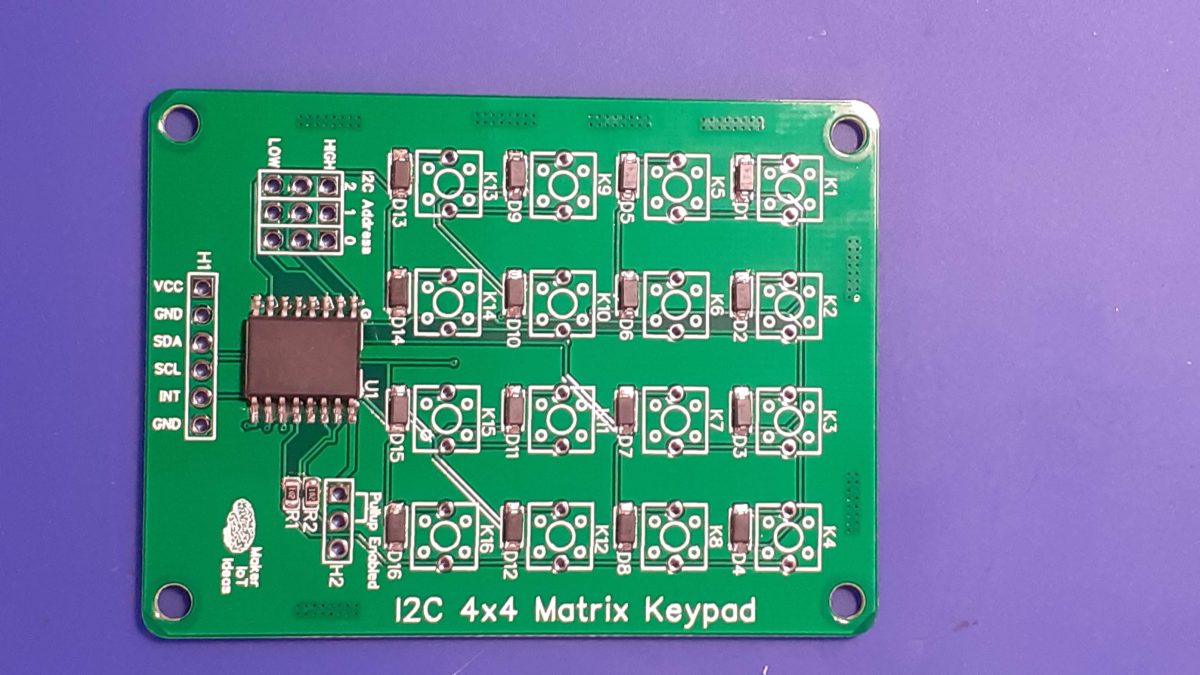
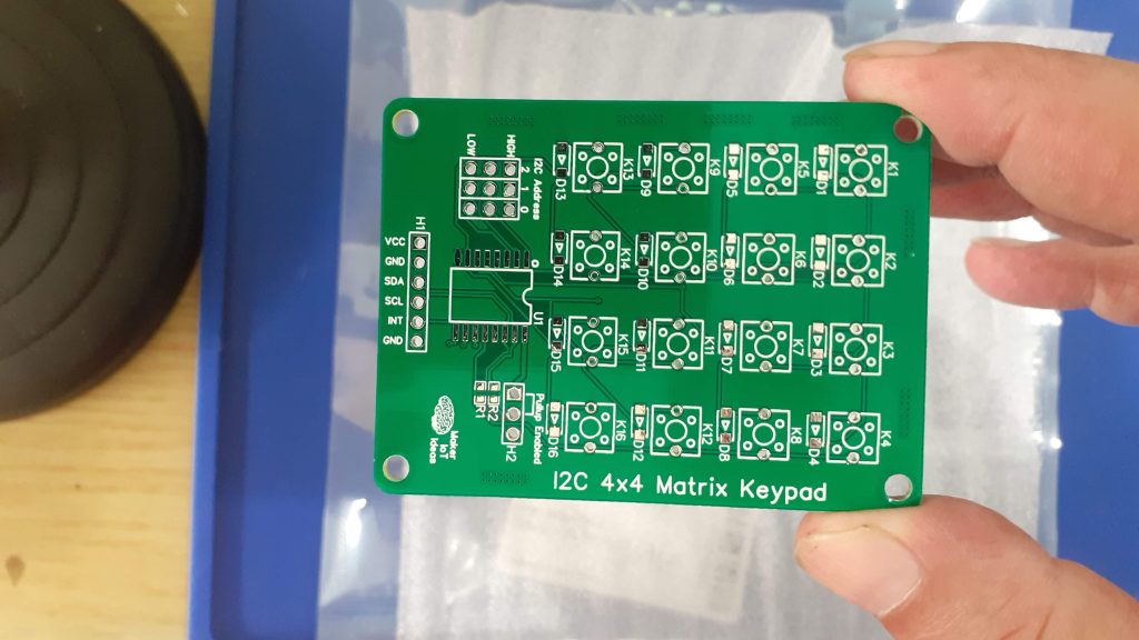
I2C Keypad PCB
3D Render of the I2C Keypad

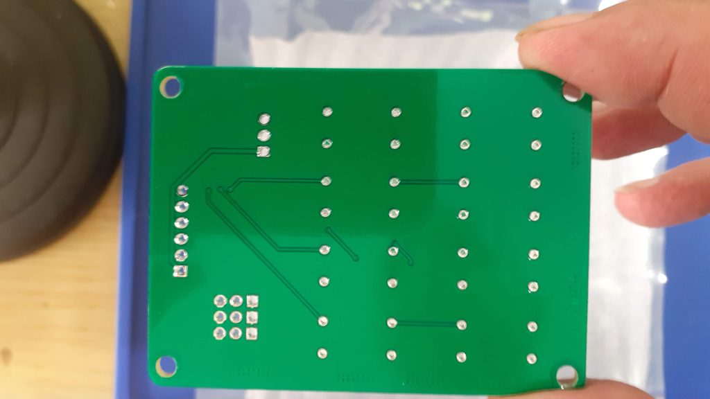
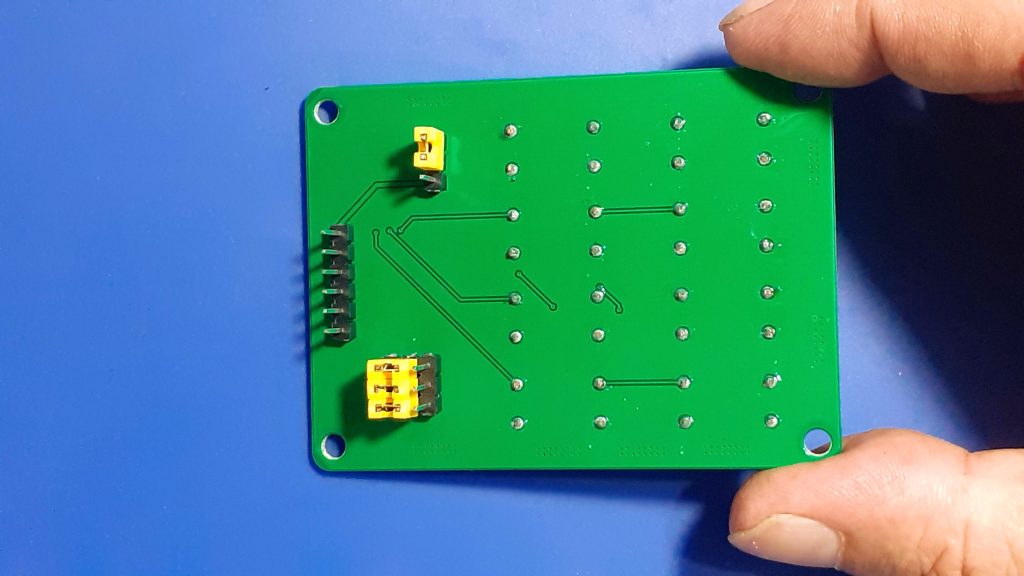
The PCB is a double-layer board of 68.8mm x 50.8mm. Male header pins provide access to the connections as well as address and pullup resistor jumpers. In my build, I have mounted these male headers on the back of the PCB. That makes it possible to mount the Keypad in an enclosure without having the jumpers “stick out” and get in the way.

The top layer of the I2C Keypad PCB
Bottom Layer

Manufacturing

I choose PCBWay for my PCB manufacturing.
This month, PCBWay is also celebrating its 9th anniversary, and that means that there are quite a lot of very special offers available.

Why?
What makes them different from the rest?

PCBWay‘s business goal is to be the most professional PCB manufacturer for prototyping and low-volume production work in the world. With more than a decade in the business, they are committed to meeting the needs of their customers from different industries in terms of quality, delivery, cost-effectiveness and any other demanding requests. As one of the most experienced PCB manufacturers and SMT Assemblers in China, they pride themselves to be our (the Makers) best business partners, as well as good friends in every aspect of our PCB manufacturing needs. They strive to make our R&D work easy and hassle-free.

How do they do that?

PCBWay is NOT a broker. That means that they do all manufacturing and assembly themselves, cutting out all the middlemen, and saving us money.

PCBWay’s online quoting system gives a very detailed and accurate picture of all costs upfront, including components and assembly costs. This saves a lot of time and hassle.

PCBWay gives you one-on-one customer support, that answers you in 5 minutes ( from the Website chat ), or by email within a few hours ( from your personal account manager). Issues are really resolved very quickly, not that there are many anyway, but, as we are all human, it is nice to know that when a gremlin rears its head, you have someone to talk to that will do his/her best to resolve your issue as soon as possible.

Find out more here

Assembly

The assembly of this PCB was quite easy and quick. A stencil is not required. All SMD components are 0805 or bigger. It would thus be quite easy to solder them all by hand with a fine-tipped soldering iron.

I have however used soldering paste and hot air to reflow the components, as it is the fastest, in my opinion, and definitely looks neater than hand soldering.

After placing SMD components onto solder paste – ready for reflow soldering
After Reflow soldering with Hot Air

The board is now ready to solder the switches and header pins in place. As already mentioned above, I chose to assemble the headers on the back of the PCB to prevent them from interfering with any enclosure that I may later use with the keypad.

Final Assembly
Note that I assembled the headers onto the back of the PCB.

Testing and Coding

Testing the keypad consisted of a few steps, the first of which was ensuring that there were no short circuits, as well as that all the momentary switches worked.
This was done with a multimeter in continuity as well as diode mode, with probes alternatively on each column and row in turn, while pressing the buttons.

The next stage was testing the I2C IO Expander. This was done with a simple I2C Scanning sketch on an Arduino Uno. It did not do a lot, but, I could see that the PCF8574 is responding to its address and that the pullup resistors work when enabled. This test was repeated with my own ESP8266 and ESP32 boards, this time with pullup resistors disabled, as these boards already have them onboard.

Coding came next, and it was another case of perspectives. It seems like all commercial keypads do not have diodes. This affects the way that they work with a given library. It seems that software developers and hardware developers have different understandings of what a row and a column is.

This meant that, due to the fact that I have diodes on each switch, and the way that the library work – which pins are pulled high and which are set as inputs -, I had to swap around my rows and columns in the software to get everything to work. On a keypad with the diodes replaced with 0-ohm links, that was not needed.

A short test sketch follows below:

Note that with was run on an ESP8266-12E, therefore the Wire.begin() function was changed to Wire.begin(4,5); in order to use GPIO 4 and GPIO 5 for I2C

Another point to note is that the keypad Layout will seem strange. Remember that this is due to the diodes in series on each switch. That forces us to swap around the Rows and the Columns in the software, resulting in a mirrored and rotated left representation of the keypad. It looks funny, but believe me, it actually still works perfectly.

#include <Wire.h>
#include "Keypad.h"
#include <Keypad_I2C.h>

const byte n_rows = 4;
const byte n_cols = 4;

char keys[n_rows][n_cols] = {
    {'1', '4', '7', '*'},
    {'2', '5', '8', '0'},
    {'3', '6', '9', '#'},
    {'A', 'B', 'C', 'D'}};

byte rowPins[n_rows] = {4, 5, 6, 7};
byte colPins[n_cols] = {0, 1, 2, 3};

Keypad_I2C myKeypad = Keypad_I2C(makeKeymap(keys), rowPins, colPins, n_rows, n_cols, 0x20);

String swOnState(KeyState kpadState)
{
    switch (kpadState)
    {
    case IDLE:
        return "IDLE";
        break;
    case PRESSED:
        return "PRESSED";
        break;
    case HOLD:
        return "HOLD";
        break;
    case RELEASED:
        return "RELEASED";
        break;
    } // end switch-case
    return "";
} // end switch on state function

void setup()
{
    // This will be called by App.setup()
    Serial.begin(115200);
    while (!Serial)
    { /*wait*/
    }
    Serial.println("Press any key...");
    Wire.begin(4,5);
    myKeypad.begin(makeKeymap(keys));
}

char myKeyp = NO_KEY;
KeyState myKSp = IDLE;
auto myHold = false;

void loop()
{

    char myKey = myKeypad.getKey();
    KeyState myKS = myKeypad.getState();

    if (myKSp != myKS && myKS != IDLE)
    {
        Serial.print("myKS: ");
        Serial.println(swOnState(myKS));
        myKSp = myKS;
        if (myKey != NULL)
            myKeyp = myKey;
        String r;
        r = myKeyp;
        Serial.println("myKey: " + String(r));
        if (myKS == HOLD)
            myHold = true;
        if (myKS == RELEASED)
        {
            if (myHold)
                r = r + "+";
            Serial.println(r.c_str());
            myHold = false;
        }
        Serial.println(swOnState(myKS));
        myKey == NULL;
        myKS = IDLE;
    }
}

Conclusion

This project once again delivered what I set out to achieve. It has some quirks, but nothing serious. Everything works as expected, both in the Arduino IDE/platform IO realm, as well as in ESPHome. It is worth noting that in ESPHome, we do not need to swap the rows and columns to use the Keypad component. Do remember to leave the has_diodes flag to false though…

A quick P-MOS MOSFET Driver Board

Introduction

A driver is needed to switch a P-Channel MOSFET because the gate of a P-Channel MOSFET needs to be driven to a voltage that is more negative than the source in order to turn it on. This can be difficult to do with low-voltage logic, such as 5V or 3.3V. A driver can provide the necessary voltage and current to turn on the P-Channel MOSFET, even when the logic voltage is low.

Here are some of the benefits of using a driver to switch a P-Channel MOSFET:

  • Increased switching speed: A driver can provide the necessary current to charge and discharge the gate capacitance of the P-Channel MOSFET quickly, which results in faster switching speeds.
  • Reduced power consumption: A driver can help to reduce power consumption by providing the necessary current in a short pulse, rather than a continuous stream of current.
  • Improved noise immunity: A driver can help to improve noise immunity by providing a clean and isolated signal to the gate of the P-Channel MOSFET.

If you are using a P-Channel MOSFET in your circuit, it is a good idea to use a driver to switch it. This will help to ensure that the MOSFET is switched quickly and efficiently and that it is protected from noise.

Here are some of the different types of drivers that can be used to switch P-Channel MOSFETs:

  • Logic level drivers: These drivers are designed to work with low-voltage logic, such as 5V or 3.3V. They typically have a high output voltage, which can be used to drive the gate of a P-Channel MOSFET.
  • High-side drivers: These drivers are designed to provide a high voltage to the gate of a P-Channel MOSFET. They are often used in circuits where the P-Channel MOSFET is used to switch a high-voltage rail.
  • Isolated drivers: These drivers provide an isolated signal to the gate of the P-Channel MOSFET. This is useful in circuits where it is important to prevent noise from entering the circuit.

Why did I decide to design this prototype?

The Story behind the prototype

This driver PCB is part of a solution for a project involving a set of 6v LED lights.
Each of the LED lights requires +/- 300mA @ 6v to operate efficiently.
I want to control these from a Microcontroller, either an ESP32 or even the XIAO RP2040 or similar. The current sink capability of an individual GPIO pin on these microcontrollers is limited, in the case of the RP2040 it is limited to 3mA per pin.

This prototype is an attempt to test out some basic driver ideas that might perform correctly for my particular needs, being

  • To stay within the limitations of the particular microcontroller GPIO current specifications
  • To be able to use any of the particular microcontrollers, without having to design a specific solution tailored to a specific device

The Schematic

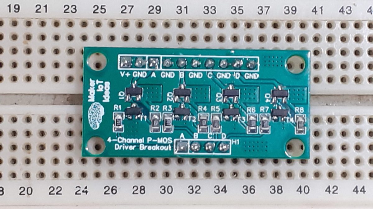
I decided to keep things extremely simple to start with, using a very simple circuit consisting of only 4 components per channel. These are :
– an S9013 NPN BJT Transistor, capable of switching up to 500mA of current
– a SI2301 P-Channel Logic Level MOSFET, capable of switching up to 2.3A
– 10k pullup-resitor
– 1k resistor on the base of the BJT


The theory of operation is as follows:
The pullup resistor, R8, keeps the gate of the MOSFET (Q4) positive, thus ensuring that Q4 stays turned off when T4 is turned off. A HIGH signal at B4 will turn on T4, which will in turn pull the gate of Q4 to ground, turning Q4 on in the process.
That will in turn turn on the load ( connected at 4+ and 4- ).

It is important to note here that the value of R8, 10K at the moment, is not finalised, and may change to increase the performance of the circuit.

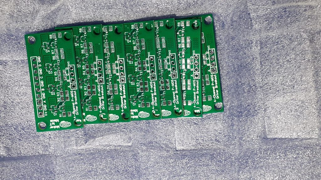
The PCB

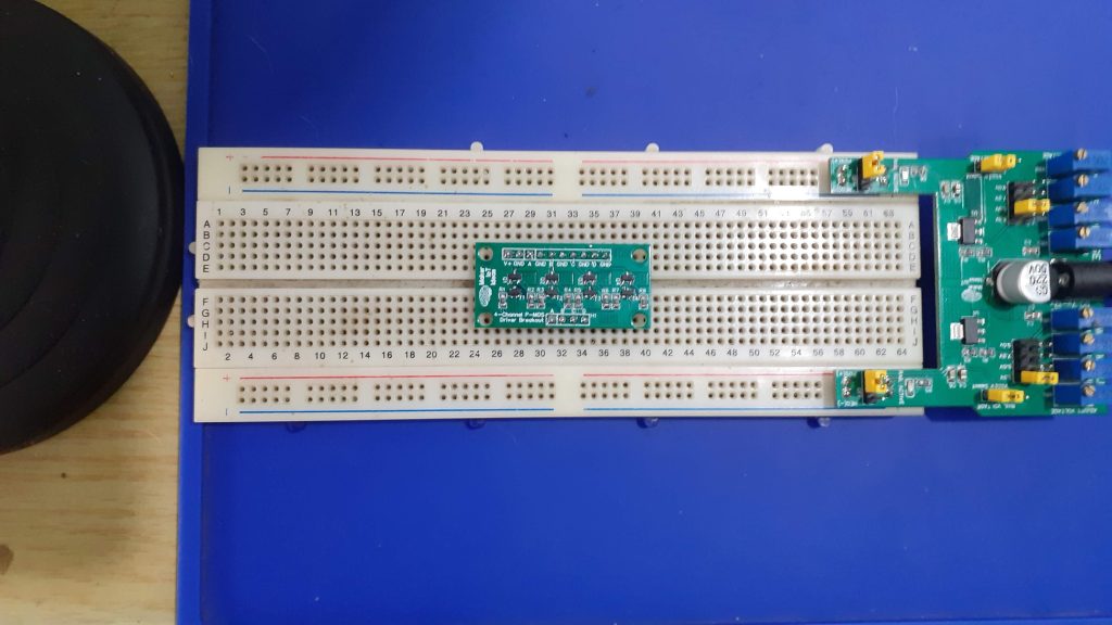
The board was made to fit on a standard breadboard or be used as a standalone module, depending on the position of the male header pins.


Manufacturing


I choose PCBWay for my PCB manufacturing.
This month, PCBWay is also celebrating its 9th anniversary, and that means that there are quite a lot of very special offers available.


Why? What makes them different from the rest?
PCBWay‘s business goal is to be the most professional PCB manufacturer for prototyping and low-volume production work in the world. With more than a decade in the business, they are committed to meeting the needs of their customers from different industries in terms of quality, delivery, cost-effectiveness and any other demanding requests. As one of the most experienced PCB manufacturers and SMT Assemblers in China, they pride themselves to be our (the Makers) best business partners, as well as good friends in every aspect of our PCB manufacturing needs. They strive to make our R&D work easy and hassle-free.

How do they do that?

PCBWay is NOT a broker. That means that they do all manufacturing and assembly themselves, cutting out all the middlemen, and saving us money.

PCBWay’s online quoting system gives a very detailed and accurate picture of all costs upfront, including components and assembly costs. This saves a lot of time and hassle.

PCBWay gives you one-on-one customer support, that answers you in 5 minutes ( from the Website chat ), or by email within a few hours ( from your personal account manager). Issues are really resolved very quickly, not that there are many anyway, but, as we are all human, it is nice to know that when a gremlin rears its head, you have someone to talk to that will do his/her best to resolve your issue as soon as possible.

Find out more here

Assembly

The assembly of the PCB does not require any special tools, and can be done completely by hand if you choose. A very fine-tipped soldering iron should be perfect.

I chose to go the hot-air and solder-paste route, as it is faster, and looks neater in the end. The use of a stencil was not required.

The total assembly took about 5 minutes in total.

Testing

Testing the completed PCB module was performed with one of the LED light modules connected to each MOSFET Channel in turn, and then applying a voltage signal, or ground, to the control pin ( marked A to D on the picture above)

That was followed by connecting an Oscilloscope and Signal Generator to the control pins, as well as the outputs, and observing the waveforms during operation. A square wave output from the signal generator provided the switching signal.

Conclusion

The module works as expected, but the pullup resistor value needs to be fine-tuned to provide a better switching response on the MOSFET at high frequency.
I am however happy with the initial performance, and can now move on to improving the circuit to perform to my specifications.


A Reliable Matrix Keypad

What is a matrix keypad?

A matrix keypad is a type of keypad that uses a matrix of wires to connect the keys to the microcontroller. This allows for a smaller and more compact keypad than a traditional keypad, which uses a single row and column of wires for each key. Matrix keypads are also more reliable than conventional keypads, as they are less susceptible to damage from dirt and moisture.

How does a matrix keypad work?

A matrix keypad is made up of a number of rows and columns of keys. Each key is connected to two wires, one for the row and one for the column. When a key is pressed, it completes a circuit between the row and column wires. The microcontroller can then determine which key is pressed by checking which row and column wires are connected.

Why use a matrix keypad?

There are a number of reasons why you might want to use a matrix keypad in your project. Here are a few of the most common reasons:

  • Smaller size and footprint.
  • Reliability.
  • Cost savings.

What makes my design different from most others out there?

While the matrix keypad in its simplest form is constructed from only wires and switches, that simple approach can sometimes have some unwanted effects, especially when pressing multiple keys at the same time – a phenomenon called ghosting – where you get phantom keypresses. This is easily eliminated by adding a diode in series with each switch, usually on the row connection.

That single component fixes ghosting reliably but does not come without its own problems, the most important of these being that a keypad with diodes becomes “polarised” – current can only flow in a single direction through a switch. This can cause problems with some third-party libraries, as the designer of the keypad and the designer of the library very often has quite different ideas of what a row and a column mean in a keypad.

This is important, – here we go down the rabbit hole; in my understanding of the keypad scanning routine, a column runs from top to bottom, and a row from left to right. Keeping this in mind, the microcontroller will alternatively set each column HIGH, and configure each row as an input. When a key is pressed, current will flow from the specific column GPIO, through the switch, and into the Row GPIO, sending the input pin HIGH…

It is also possible to configure the columns as inputs, with internal pullups enabled, and have each Row pin as an output, configured to sink ( pull current to ground). This will cause the specific column to go low – thus identifying the pressed key…

These different ways of handling the problem of reading a key, and believe me, there are actually more variations, create a few unique problems. We may have to swap rows and columns as far as pin connections and firmware are concerned, as well as define a custom “keymap” to assign values to each key.

The Schematic

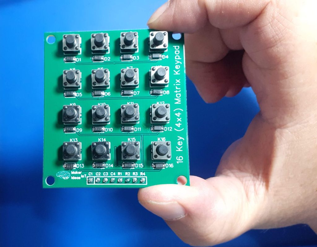
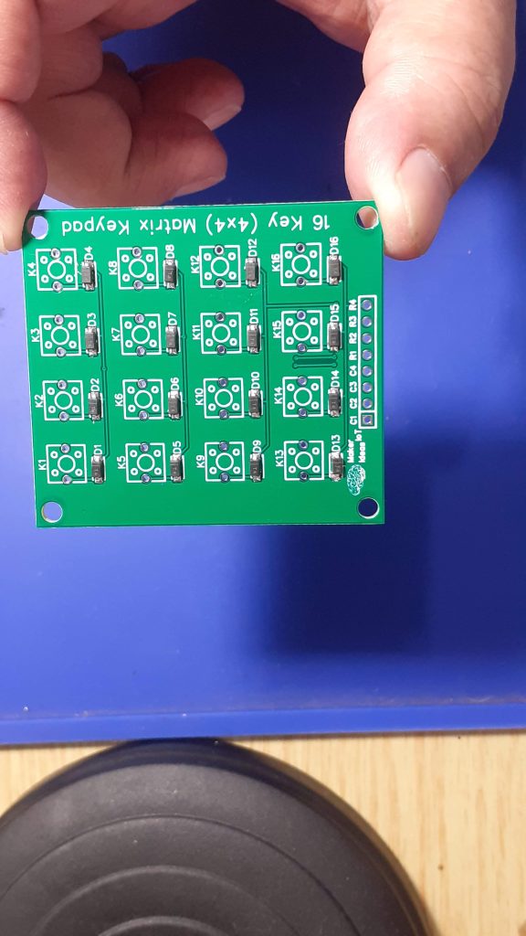
As we can see above, the schematic is very basic. 16 switches, 16 diodes and a single 8-way header pin. Pin 1 to 4 on the header is connected to Columns 1 to 4, and Pin 5 to 8 is connected to Rows 1 to 4.

The diodes prevent “ghosting currents from flowing into other keys in a row when multiple keys are pressed together. They also seem to help with other stray signals and interference.

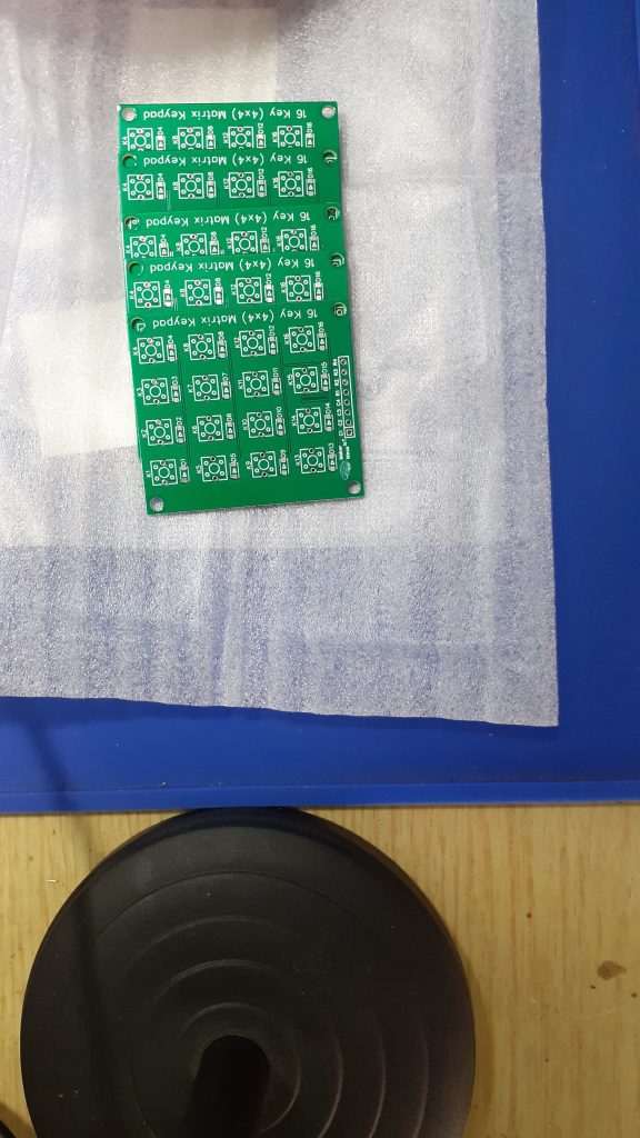
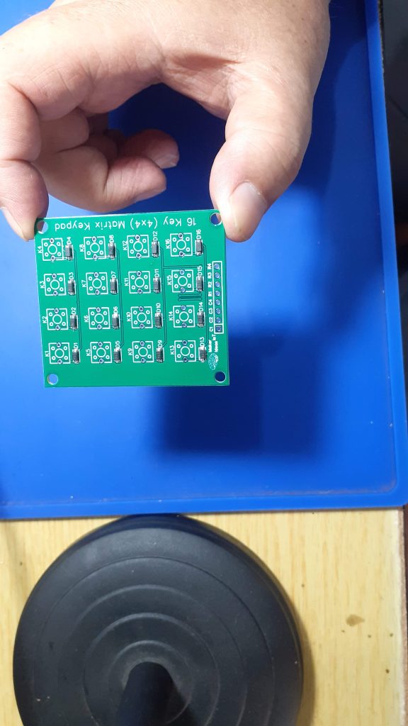
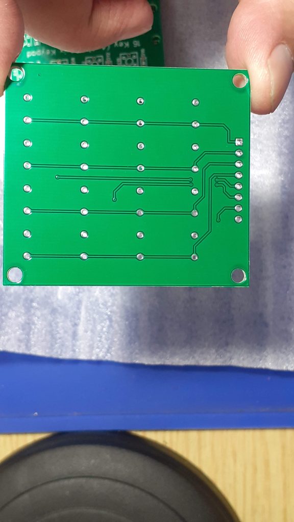
The PCB

The PCB is a simple double-layer board. All components are mounted on the top layer.

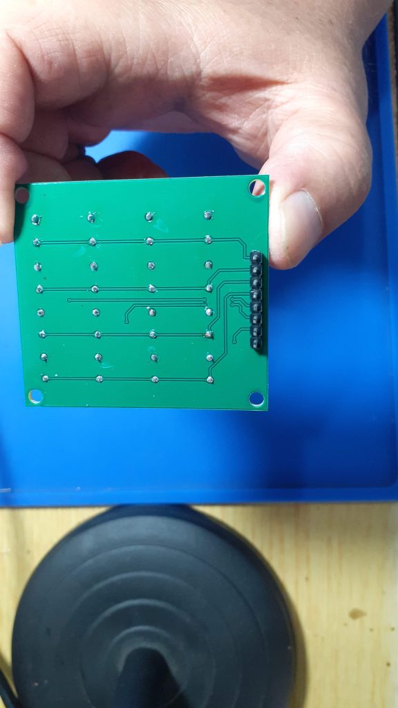
To limit interference from stray signals, I have routed rows and columns on opposite sides of the PCB where possible.

Manufacturing

I choose PCBWay for my PCB manufacturing.
This month, PCBWay is also celebrating its 9th anniversary, and that means that there are quite a lot of very special offers available.


Why? What makes them different from the rest?
PCBWay‘s business goal is to be the most professional PCB manufacturer for prototyping and low-volume production work in the world. With more than a decade in the business, they are committed to meeting the needs of their customers from different industries in terms of quality, delivery, cost-effectiveness and any other demanding requests. As one of the most experienced PCB manufacturers and SMT Assemblers in China, they pride themselves to be our (the Makers) best business partners, as well as good friends in every aspect of our PCB manufacturing needs. They strive to make our R&D work easy and hassle-free.

How do they do that?

PCBWay is NOT a broker. That means that they do all manufacturing and assembly themselves, cutting out all the middlemen, and saving us money.

PCBWay’s online quoting system gives a very detailed and accurate picture of all costs upfront, including components and assembly costs. This saves a lot of time and hassle.

PCBWay gives you one-on-one customer support, that answers you in 5 minutes ( from the Website chat ), or by email within a few hours ( from your personal account manager). Issues are really resolved very quickly, not that there are many anyway, but, as we are all human, it is nice to know that when a gremlin rears its head, you have someone to talk to that will do his/her best to resolve your issue as soon as possible.

Find out more here

Assembly

This project does not require a lot of specialised equipment to assemble. The SMD diodes can easily be soldered by hand, the same with the switches and 8-way header. In my case, I chose to solder the header pins on the back of the PCB, that way, I can later use the keypad in a suitable enclosure without having wires in the way.

Testing and Coding

Testing a matric keypad can sometimes be a challenge. In my case, a multimeter with clip leads, set to diode mode, with the leads connected to each column and row in turn, while minding the polarity, and pressing each key in that row in turn, verified continuity.

With that done, it was time to put my trusted Cytron Maker Uno to work, as this Arduino Clone has the added benefit of having LEDs on each of the GPIO lines, thus making it very easy to see what is happening.

I made use of a Keypad library in the Arduino IDE, mainly to cut down on the amount of coding, but also because it is easier to use a working piece of code, and then adapt that to my keypad.

Detailed Code examples for ESPHome are available on Patreon

/* @file CustomKeypad.pde
|| @version 1.0
|| @author Alexander Brevig
|| @contact alexanderbrevig@gmail.com
||
|| @description
|| | Demonstrates changing the keypad size and key values.
|| #

Edited by MakerIoT2020, with minor changes to make it function correctly with my custom keypad.
I have also added a simple LED blinking routine to show that the Arduino is “alive” and that the Keypad code seems to be NON-blocking – which is quite important to me.

*/
#include <Keypad.h>

const byte ROWS = 4; //four rows
const byte COLS = 4; //four columns
//define the symbols on the buttons of the keypads
char hexaKeys[ROWS][COLS] = {
{‘1′,’4′,’7′,’*’},
{‘2′,’5′,’8′,’0’},
{‘3′,’6′,’9′,’#’},
{‘A’,’B’,’C’,’D’}
};
byte rowPins[ROWS] = {2,3,4,5}; //connect to the row pinouts of the keypad
byte colPins[COLS] = {6,7,8,9}; //connect to the column pinouts of the keypad
/*
* Due to libraries being written by different people, and our definitions about
* what a row and a column are, is different, note that the rows in the code
* is actually the columns on my PCB. This becomes true, due to the fact that my
* PCB has Diodes on each switch, and that thus makes current flow in only one
* direction///
*
* it also has the “side effect” that keys are layout in a strange “mirrored” and
* rotated way in the firmware.
* it does however NOT affect the correct operation of the Keypad Module at all
*
*/

const int LEDPin = LED_BUILTIN;
int ledState = LOW;
unsigned long prevmillis = 0;
const long interval = 1000;

//initialize an instance of class NewKeypad
Keypad customKeypad = Keypad( makeKeymap(hexaKeys), rowPins, colPins, ROWS, COLS);

void setup(){
Serial.begin(115200);
pinMode(LEDPin,OUTPUT);
}

void loop(){
unsigned long currentMillis = millis();
if (currentMillis – prevmillis >= interval) {
prevmillis = currentMillis;
if (ledState == LOW) {
ledState = HIGH;
} else {
ledState = LOW;
}
digitalWrite(LEDPin,ledState);
}
char customKey = customKeypad.getKey();

if (customKey){
Serial.println(customKey);
}
}

This code works very well and allowed me to verify the correct operation of the keypad.

In conclusion

Making my own Keypad Module is a project that is long overdue. I have purchased a few online over the years, and as they were mostly of the membrane type, they did not last very long – it must be something to do with the ultra-cheap flexible PCB ribbon connector, since a quality membrane keypad can be quite expensive, and usually lasts quite a long time.

Having my own module available to experiment with will allow me to do some long-delayed improvements to many of my IoT modules. That code, mostly YAML for ESPHome, will be made available on Patreon.

My Own DC-DC Buck Converter

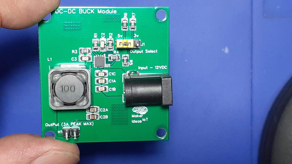
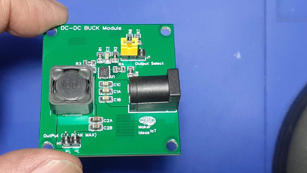
Dc-to-DC Back converters have a lot of advantages over traditional linear voltage regulator solutions. Most of these advantages are related to the smaller size of these circuits, in comparison to their linear counterparts, as well as their higher efficiency and lower power consumption to name a few.

I am by no means a power supply guy, and as such, I usually buy my power supply modules. The same also applies to boost and buck converters. I am usually quite comfortable leaving the design of these critical parts to those who actually know what they are doing.

It thus seemed like a reasonable challenge to actually try and design and build one by myself, and that will be the story behind this post.

Finding a suitable driver IC

This journey started at a very strange place. When I decided to go ahead and build this Buck converter module, I had no specific driver IC in mind. I was thus browsing through the long list of dc-to-dc- buck converters on my component suppliers’ website, randomly pulling up a datasheet to take a closer look, mainly looking for something with as few external components as possible, while also having a decent current supply capability, as well as being able to operate on an input supply of 4v to about 24v, which is well within my usual range…

I eventually settled on the MPS MP9943. Definitely not the cheapest but still affordable, and in a QFN8 package, so that I am still able to actually solder it to a PCB!

-Wide 4V to 36V Continuous Operating Input
Range
-85mΩ/55mΩ Low RDS(ON) Internal Power
MOSFETs
-High-Efficiency Synchronous Mode Operation
-410kHz Switching Frequency
-Synchronizes from 200kHz to 2.2MHz
-External Clock
-High Duty Cycle for Automotive Cold-crank
-Internal Power-Save Mode
-Internal Soft-Start
-Power Good Indicator
-Over Current Protection and Hiccup
-Thermal Shutdown
-Output Adjustable from 0.8V
-Available in an QFN-8 (3mmx3mm)
package

and with a peak current supply of up to 3A – Not too bad at all.

The actual design

As mentioned already, I am not ( or at least I don’t see myself) a power supply design expert. I believe I am perfectly capable with the linear stuff, by switchmode was never my strong point 🙂 This prototype will just be based on the recommended design in the datasheet, at least for the first version, and then, later versions may feature some customisation as actually needed.

From the picture above, we can see that there are indeed not a lot of external components required. And in my humble opinion, the efficiency vs load also seems to be quite reasonable.

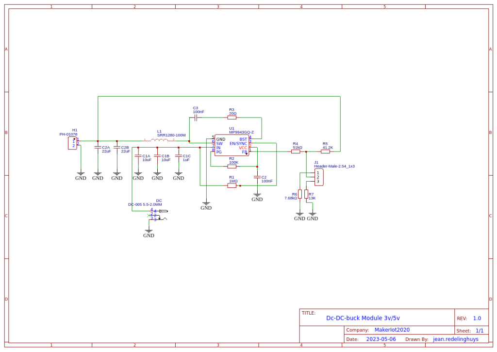
I thus went ahead and started reading this datasheet in detail. I found two typical-use circuits with recommended component values, from which I build my prototype.

I chose to combine these two circuits to give me a variable output module, that will be selectable between 5v and 3v.

I also chose an inductor with a 6A maximum current rating, as the datasheet states that we should choose one with at least a 25% higher current rating than our peak requirement. My logic here was that 100% would be a good number, as the inductor would in theory never saturate?? as well as produce less heat etc ?? Please comment on this, as I may be barking up the wrong tree here 🙂


The schematic above is what I came up with. A jumper will allow the selection of the output voltage, as this is determined by the value of the resistor at R8, in my case 13K or 7.68k… I also assume that that resistor can later be replaced by a 20k trimpot or similar to give a truly variable output.

PCB Layout

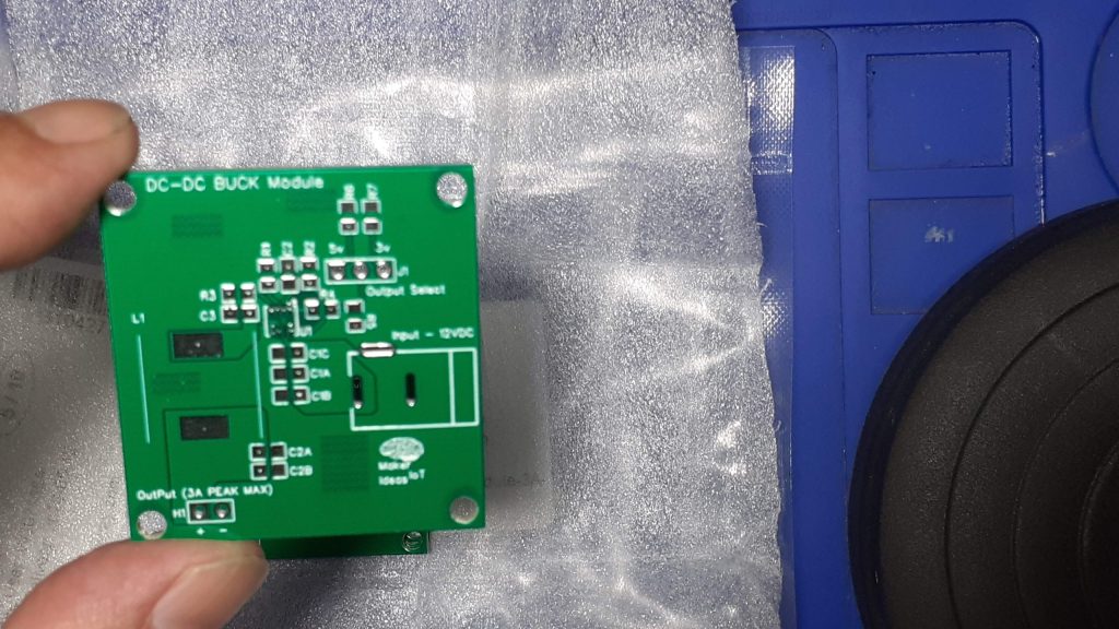
The PCB layout was an attempt to follow the datasheet recommendations as closely as possible, while still having my own design. I am also aware that I may have wasted quite a bit of space, but for now, my focus is on getting a working design. I can always try to squeeze it into a smaller space later.

Manufacturing

I choose PCBWay for my PCB manufacturing. Why? What makes them different from the rest?

PCBWay‘s business goal is to be the most professional PCB manufacturer for prototyping and low-volume production work in the world. With more than a decade in the business, they are committed to meeting the needs of their customers from different industries in terms of quality, delivery, cost-effectiveness and any other demanding requests. As one of the most experienced PCB manufacturers and SMT Assemblers in China, they pride themselves to be our (the Makers) best business partners, as well as good friends in every aspect of our PCB manufacturing needs. They strive to make our R&D work easy and hassle-free.

How do they do that?

PCBWay is NOT a broker. That means that they do all manufacturing and assembly themselves, cutting out all the middlemen, and saving us money.

PCBWay’s online quoting system gives a very detailed and accurate picture of all costs upfront, including components and assembly costs. This saves a lot of time and hassle.

PCBWay gives you one-on-one customer support, that answers you in 5 minutes ( from the Website chat ), or by email within a few hours ( from your personal account manager). Issues are really resolved very quickly, not that there are many anyway, but, as we are all human, it is nice to know that when a gremlin rears its head, you have someone to talk to that will do his/her best to resolve your issue as soon as possible.

Find out more here

Assembly

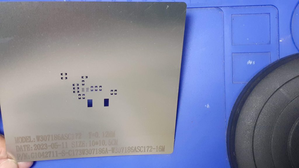
After receiving the PCBs back from the factory, and receiving the components from the supplier, I started on the assembly. While uneventful, It was worth mentioning that this project does require a stencil. The DFN-8 package is quite small (only 3mmx3mm), with eight leads, so that makes for some tiny spacing between them. As it is also a leadless package, I did not want to chance to have too much solder paste in there.

As we can clearly see in the picture above, the pads are super tiny. The other components are 0805 ( for reference).

My standard way for assembling DFN packages is to actually level the part of the PCB while reflowing the PCB with a hotplate. Then, when the solder has all melted and is in a liquid state, I carefully place the part with tweezers and remove the PCB from the hotplate.

Alternatively, I remove the PCB from the hotplate first, leaving it to cool down a bit, and then, using a hot air gun with a small nozzle, reflowing only the area where the part needs to be placed, and carefully placing it onto the melted solder.

Both of these methods seem to be working quite well, for me at least, but the hot air method does however have the risk of a bit of solder splatter, which may form unwanted bridges… The part also gets heated a bit, as it has to be held in place for a few seconds to prevent it from being blown around by the hot air.

Testing


I am quite happy to report that the module works as expected, with a steady output of 3.31v and 5.08v respectively at no load.

Under load, I tested with a 1A and 2A load respectively, both voltages are also stable. Ripple, as measured by myself, and using a “not too good” digital oscilloscope, seems to be about 110mv peak-to-peak.

Using better probes, and a better scope, I may be able to get a better and more accurate reading.

Conclusion

This was quite an exciting project, with setting myself a challenge, and actually achieving what I set out to do. While I am sure that the module in its current state may actually not quite be perfect, and that it surely has a lot of room for improvement, I am satisfied with its performance, and just plainly, the fact that it actually works!

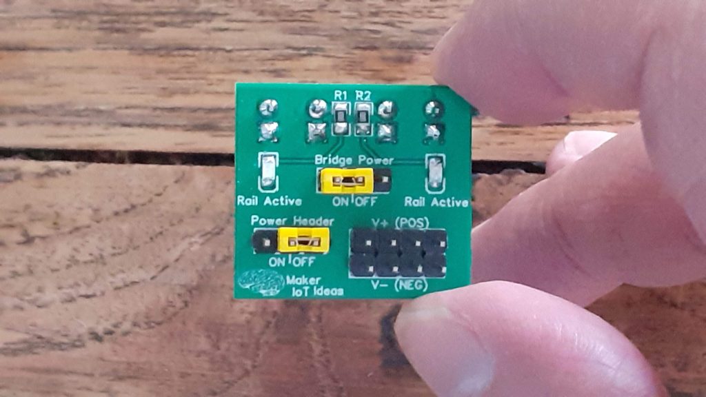
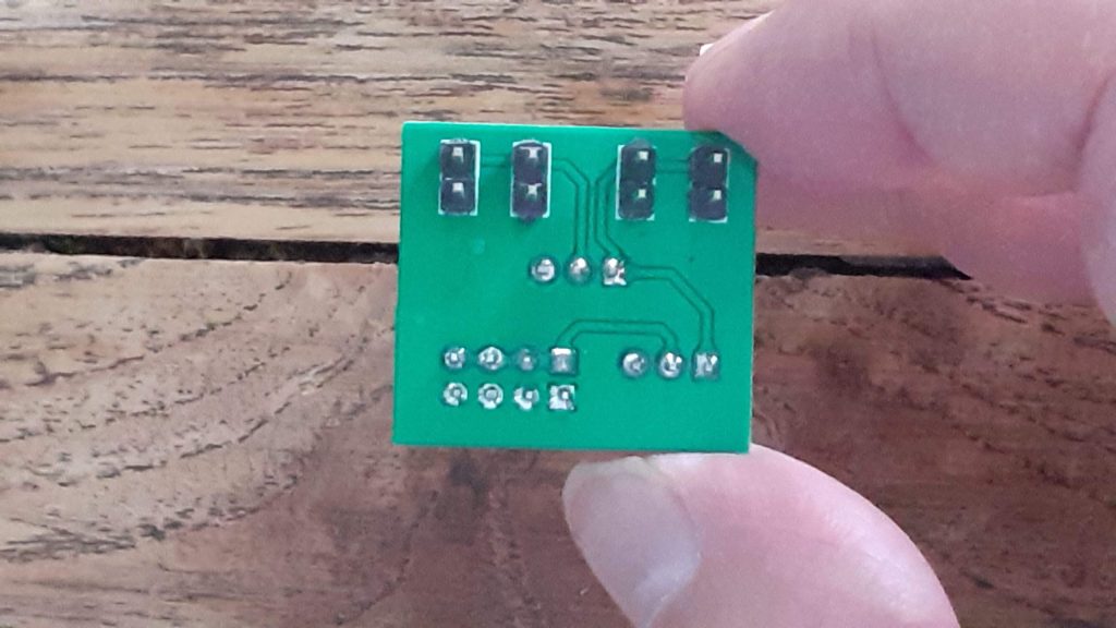
Breadboard Power Rail Bridge

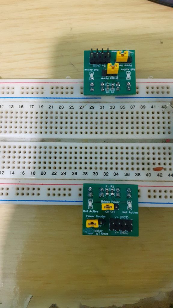
This is a sort of tongue-in-the-cheek project, that started with good intentions, and ended up wholly over-engineered and sort of “broken” due to adding “added features” like LEDs and an additional power header.

What was the initial intention?

[This is what I actually wanted to achieve]


My breadboards all have interrupted power rails, and it is thus always necessary to bridge them with jumper wires to have a continuous rail. This is needed because I very often have more than one project on a single breadboard, and do not want to have to use separate power modules for each. I also tend to test out some part of a circuit on a separate part of the breadboard, before incorporating it into the main circuit.

[ I completely overdesigned this, ending up with something completely different from what I wanted]


Wire jumpers are definitely the easier and fastest, but having been struck by a “what if I do this instead” moment, this tiny PCB was designed and subsequently sent to manufacturing…

So does it work?

Yes, it works, for its intended purpose of bridging the power rails, but that is where the wheels come off. Let me explain, trust me, it will be fun, and we can all laugh at it in the end…

Breadboard power rails are usually marked Red for positive, and Blue or Black for negative… Most people on this planet are also right-handed, and would thus place a power module on the right-hand side of a breadboard ( although some won’t..) Being left-handed myself, and still trying to please right-handed people, my power module will be “upside down” on the left-hand side of a breadboard… which is fine with me, as I remember to swap the colours of the rails in my mind, making red negative and blue positive… not a big issue is you always do it that way…

So what went wrong…

While designing this, I initially planned on a simple PCB bridge, with a jumper on the positive line, acting as a switch, and a continuous ground that is always connected.. all fine, problem number 1 being that I looked at the colours of the power rails while designing it, measuring the gaps etc to get the spacing just right…

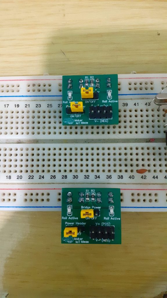
Problem number 2 is that the top and bottom rails are in the same configuration, Red at the top, blue at the bottom… and thus plugging in a bridge into either should be ok… and it really should have been, if I did not decide to add a status LED on each side of the bridge, and an additional power header… because turns out that I forgot that the bridge at the top will in effect be “mirrored” when plugged in ( and thus having components that are reversed polarity) – mirrored, due to the fact that you now have to plug the top rail bridge upside down into the breadboard, because it will otherwise interfere with the prototyping space

[This was the direct effect of my lack of attention to detail – and yes, it works perfectly in this configuration – if we ignore the wasted space on the top half of the board]

[This is the practical reality – one bridge must be installed ‘upside-down’]

Lesson learned; I can be quite scatterbrained at times, especially when juggling a few projects and customers at the same time ( I am only human anyway ). Thus this project, although it looks nice, and can be useful, needs to go back to the drawing board for a complete redesign, without all those “added features”

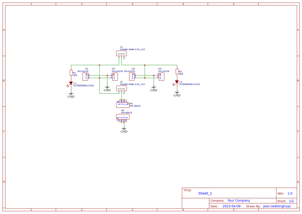
The Schematic


The schematic is straightforward, with no surprises. Two LEDs ( polarity sensitive ) and then those headers and jumpers, which also need up being polarity sensitive – in a manner of speaking

Quite different from what I originally wanted to do

Manufacturing

I choose PCBWay for my PCB manufacturing. Why? What makes them different from the rest?

PCBWay‘s business goal is to be the most professional PCB manufacturer for prototyping and low-volume production work in the world. With more than a decade in the business, they are committed to meeting the needs of their customers from different industries in terms of quality, delivery, cost-effectiveness and any other demanding requests. As one of the most experienced PCB manufacturers and SMT Assemblers in China, they pride themselves to be our (the Makers) best business partners, as well as good friends in every aspect of our PCB manufacturing needs. They strive to make our R&D work easy and hassle-free.

How do they do that?

PCBWay is NOT a broker. That means that they do all manufacturing and assembly themselves, cutting out all the middlemen, and saving us money.

PCBWay’s online quoting system gives a very detailed and accurate picture of all costs upfront, including components and assembly costs. This saves a lot of time and hassle.

PCBWay gives you one-on-one customer support, that answers you in 5 minutes ( from the Website chat ), or by email within a few hours ( from your personal account manager). Issues are really resolved very quickly, not that there are many anyway, but, as we are all human, it is nice to know that when a gremlin rears its head, you have someone to talk to that will do his/her best to resolve your issue as soon as possible.

Find out more here

Conclusion

This project served many purposes beyond the actual use of the PCB that was designed. In a way, I am quite happy that I screwed up so badly on this one – here is the reason why:

Because I do quite a lot of PCB design each month, for customers or personal projects, I often tend to get a bit over-confident, and also rush things through,
while believing that I will catch every mistake before I send something off to production. Normally, I am quite good at that, and my error rate is actually quite low… But, This month, being quite busier than usual, and having had a fair amount of distractions, served as the perfect lesson to drag me down a notch or two, and remind me that I have to be way more attentive, especially when things are going hectic, and there are a few projects to juggle around at the same time.

The second reason why it is a good thing when the wheels come off like this, once in a while, is that it serves as a perfect example of what your PCB manufacturer’s actual job is. So, this is especially for the new guys that may not know this: Your PCB Manufacturer has only one job – To manufacture your PCB EXACTLY AS YOU DESIGNED IT – Scary, right? Sure, they will let you know if your design falls outside of their tolerances of capabilities. They will let you know if your board fails a flying probe test if you have that kind of arrangement with them… But it is NEVER their job to correct or attempt to change any of your design files.

So, what is the moral of the story, regarding both of the points that I made above?

If you screw up on the design, it is your, and only your fault. Nobody else is to blame, ever. The buck stops with you, the designer.

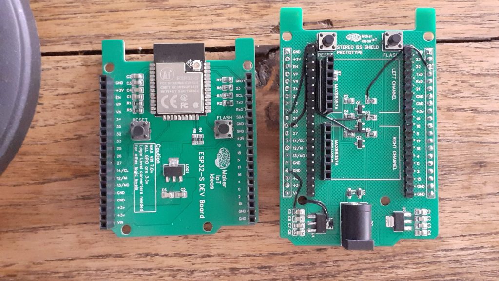
Stereo I2S Shield for ESP32-S Dev Board

Sound or music adds another level of complexity to any project. Having the ability to easily add it as a shield, allows for a reduced level of this complexity, and hopefully stimulates some inspiration along the way.

This was the thought process that inspired this Stereo I2S Shield, for use with my ESP32-S Dev Board. During the design process, and actually, before, many things happened that turned this project into a slightly more complicated task than I have initially accounted for.

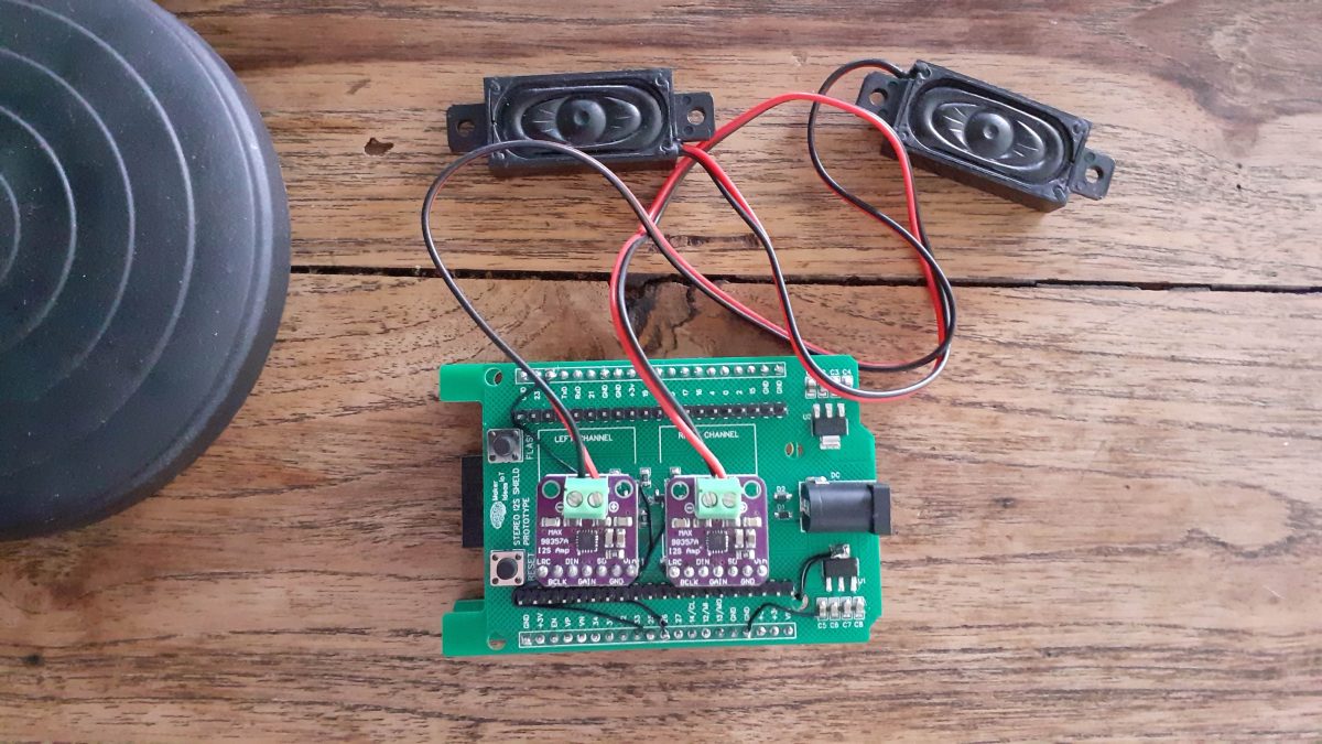
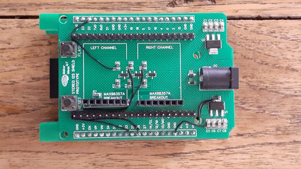
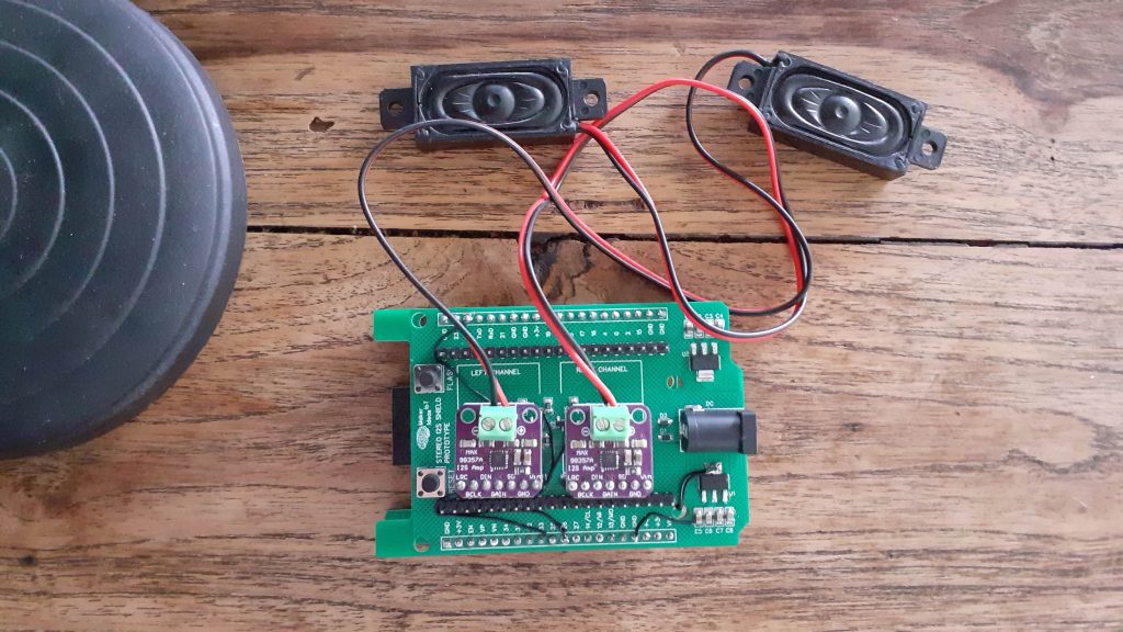
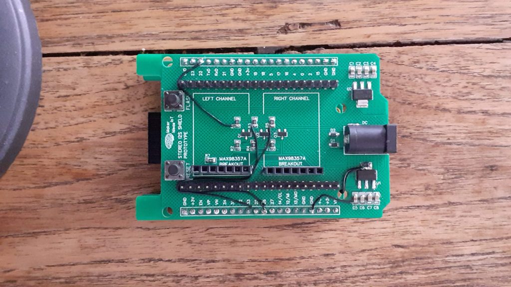
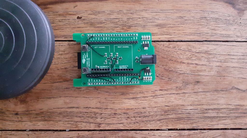
The short and sweet is that I made a few silly mistakes on the PCB, which, for the prototype at least, has been fixed with a few jumper wires. [ I have since updated the Gerber files with the correct design, omitting these silly mistakes.]

Let us take a look at what happened.

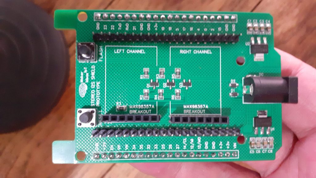
  1. I forgot the ground connection on the 5v Regulator, and since I placed extensive ground copper pours on both sides of the PCB, I missed that one completely.
  2. I forgot to connect the 5v supply to the Max98357A breakout headers
  3. I also completely forgot to connect any signal traces to these breakouts
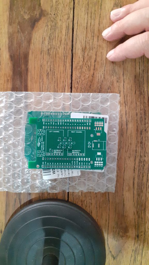
  4. The breakouts were placed on the wrong side of the PCB ( if looking top to bottom on the picture below, they should be towards the top)

How does this happen, and most importantly, why would I even mention my mistakes here, in public?

The most important here is that I am human. Humans make mistakes. Rushing through converting a design that works perfectly on a breadboard onto a PCB should not happen, but it does happen, and that is why the first iterations of a PCB are called prototypes. Dealing with customers, while working on a design, as well as life’s other interruptions very often results in small mistakes, which I usually catch before a board goes for manufacturing. In this case, I did not catch them until after I received the board back from the factory.

The other part of this coin is transparency. There are many many projects on the internet, some good, some excellent, and some outright terrible. Without giving a score to any of my own, my only intention is that whatever I present on this medium MUST be completely honest, my own work, and it must work. Any mistakes MUST be made public, regardless of what the public thinks of it afterwards.

With the ranting done now, let’s take a look at the board, which, after fixing the issues, actually works perfectly…

(I will make use of a rendered image showing the repaired PCB, as it will be the least confusing)


In the rendered image above, we can clearly see what it should have looked like, with the MAX98357A breakouts in their correct places, and all power and signal traces connected correctly.

Part of the reason for the mistakes on the initial prototype PCB was that I felt it necessary to add logic-level conversion to the I2S modules. The reason for that is that in order to get a bit more volume out of them, they are powered at 5v.


With the GPIO pins of the ESP32 being 3.3v, I felt that it is not warranted to take a risk and power the I2S breakouts at 5v, and send them 3.3v signals. That sparked the whole issue, with adding my standard Bss138-based logic converter circuit to the mixture.


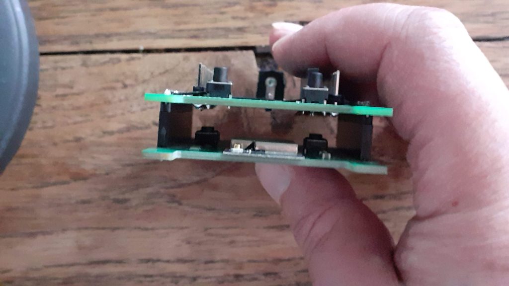
The board contains its own Flash and Reset buttons, which are slaved to the stacked ESP32-S dev board at the bottom.
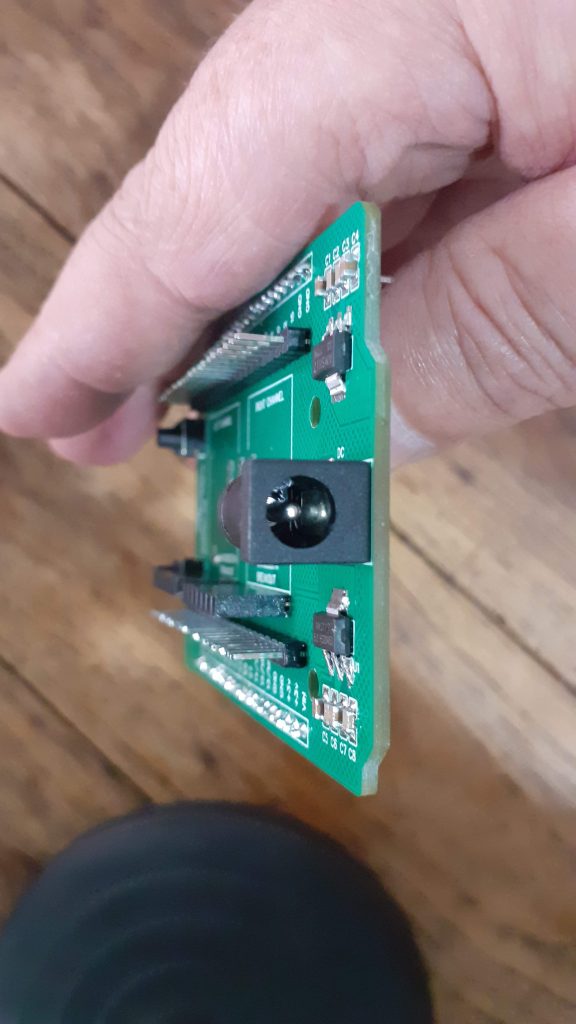
Further to that, the board provides a DC barrel connector, which will power the I2S shield, as well as the ESP32-S dev board via its Vin Pin

Since the MAX98357A breakouts seem to pull quite a bit of current ( about 500mA or more each, depending on the volume), the shield has its own voltage regulators. I have found that during the experimentation on the breadboard, the single 3.3v regulator on the ESP32-S Dev board was a bit inadequate to drive two of these modules and the ESP32 as well.

Software and Code

The code for the device is far from perfect at this stage, consisting mainly of example code that was provided by the i2s library, to which I have started making minor changes, the most significant being moving the entire audio process to an alternate core of the ESP32. This was done because the audio process seem to be blocking, and, as I plan to later add controls and displays to this device, that would result in an issue later.

/*
  Simple Internet Radio Demo
  esp32-i2s-simple-radio.ino
  Simple ESP32 I2S radio
  Uses MAX98357 I2S Amplifier Module
  Uses ESP32-audioI2S Library - https://github.com/schreibfaul1/ESP32-audioI2S

  
*/

// Include required libraries

#include "Arduino.h"
#include "WiFi.h"
#include "Audio.h"
#include "ESPmDNS.h"
#include "time.h"


// Define I2S connections
#define I2S_DOUT  22
#define I2S_BCLK  26
#define I2S_LRC   25


// Create audio object
Audio audio;

// Wifi Credentials
String ssid =    "<your ssid here>";
String password = "<your password here>";

void audioTask(void *pvParameters) {
  while(1) {
    audio.loop();
  }
}


void setup() {

  // Start Serial Monitor
  Serial.begin(115200);
  

  // Setup WiFi in Station mode
  WiFi.disconnect();
  WiFi.mode(WIFI_STA);
  WiFi.begin(ssid.c_str(), password.c_str());

  while (WiFi.status() != WL_CONNECTED) {
    delay(500);
    Serial.print(".");
  }

  // WiFi Connected, print IP to serial monitor
  Serial.println("");
  Serial.println("WiFi connected");
  Serial.println("IP address: ");
  Serial.println(WiFi.localIP());
  Serial.println("");

  // Connect MAX98357 I2S Amplifier Module
  audio.setPinout(I2S_BCLK, I2S_LRC, I2S_DOUT);
  
  // Set thevolume (0-100)
  audio.setVolume(10);

  // Connect to an Internet radio station (select one as desired)
  //audio.connecttohost("http://vis.media-ice.musicradio.com/CapitalMP3");
  //audio.connecttohost("mediaserv30.live-nect MAX98357 I2S Amplifier Module
  //audio.connecttohost("www.surfmusic.de/m3u/100-5-das-hitradio,4529.m3u");
  //audio.connecttohost("stream.1a-webradio.de/deutsch/mp3-128/vtuner-1a");
  //audio.connecttohost("www.antenne.de/webradio/antenne.m3u");
  //audio.connecttohost("0n-80s.radionetz.de:8000/0n-70s.mp3");
  //audio.connecttohost("http://live.webhosting4u.gr:1150/stream");
  audio.connecttohost("0n-80s.radionetz.de:8000/");
  disableCore0WDT();
  xTaskCreatePinnedToCore(audioTask,"audiotask",10000,NULL,15,NULL,0);
}


void loop()

{
  // Run audio player
  //audio.loop();
 
}


//

// Audio status functions

void audio_info(const char *info) {
  Serial.print("info        "); Serial.println(info);
}
void audio_id3data(const char *info) { //id3 metadata
  Serial.print("id3data     "); Serial.println(info);
}
void audio_eof_mp3(const char *info) { //end of file
  Serial.print("eof_mp3     "); Serial.println(info);
}
void audio_showstation(const char *info) {
  Serial.print("station     "); Serial.println(info);
}
void audio_showstreaminfo(const char *info) {
  Serial.print("streaminfo  "); Serial.println(info);
}
void audio_showstreamtitle(const char *info) {
  Serial.print("streamtitle "); Serial.println(info);
}
void audio_bitrate(const char *info) {
  Serial.print("bitrate     "); Serial.println(info);
}
void audio_commercial(const char *info) { //duration in sec
  Serial.print("commercial  "); Serial.println(info);
}
void audio_icyurl(const char *info) { //homepage
  Serial.print("icyurl      "); Serial.println(info);
}
void audio_lasthost(const char *info) { //stream URL played
  Serial.print("lasthost    "); Serial.println(info);
}
void audio_eof_speech(const char *info) {
  Serial.print("eof_speech  "); Serial.println(info);
}

Important parts of the code to note are as follows

disableCore0WDT();
  xTaskCreatePinnedToCore(audioTask,"audiotask",10000,NULL,15,NULL,0);

This code disables the Watchdog Timer on Core0 of the ESP32, as well as creates the audio task, which is defined earlier in the code

void audioTask(void *pvParameters) {
  while(1) {
    audio.loop();
  }
}

It is also important to note that the loop() in the code is essentially empty, with all code commented out. As mentioned above, I do plan to add additional functionality later, and in that case, there will either be other tasks running, or be some code in the main loop.

Another VERY important issue is the DOUT pin, which I have defined as GPIO22.
This pin is usually used as an I2C pin, but it seems that the I2S hardware on the ESP32-S does not like running the DOUT signal on another pin. This is not an issue, as you can assign another pin to I2C without any issue if you need to use that as well.

Manufacturing

I choose PCBWay for my PCB manufacturing. Why? What makes them different from the rest?

PCBWay‘s business goal is to be the most professional PCB manufacturer for prototyping and low-volume production work in the world. With more than a decade in the business, they are committed to meeting the needs of their customers from different industries in terms of quality, delivery, cost-effectiveness and any other demanding requests. As one of the most experienced PCB manufacturers and SMT Assemblers in China, they pride themselves to be our (the Makers) best business partners, as well as good friends in every aspect of our PCB manufacturing needs. They strive to make our R&D work easy and hassle-free.

How do they do that?

PCBWay is NOT a broker. That means that they do all manufacturing and assembly themselves, cutting out all the middlemen, and saving us money.

PCBWay’s online quoting system gives a very detailed and accurate picture of all costs upfront, including components and assembly costs. This saves a lot of time and hassle.

PCBWay gives you one-on-one customer support, that answers you in 5 minutes ( from the Website chat ), or by email within a few hours ( from your personal account manager). Issues are really resolved very quickly, not that there are many anyway, but, as we are all human, it is nice to know that when a gremlin rears its head, you have someone to talk to that will do his/her best to resolve your issue as soon as possible.

Find out more here

Assembly

Assembly was straightforward, with no issues, as all of the components can quite easily be soldered using a standard soldering iron, or hot air. This PCB does not require a stencil, but, you can of course have one made if you want to.

As mentioned in the introduction, I had to do a lot of after-assembly-hacking to get the board to work correctly. This will however not be needed with the second-generation PCB, as I have already fixed all those issues on the Gerber files.

Picture Gallery

Low BOM cost 4-cell 18650 Charger

Due to their high capacity and relatively low cost, LiPo cells are almost everywhere these days. This Low BOM cost 4-cell 18650 Charger module is my attempt to solve another issue.

The 18650 Lipo cell is quite common in my lab, and for an excellent reason, as mentioned above, they are cost-effective and also store quite a bit of energy. recharging them after use has however been quite a lengthy exercise in the past.

The usual process involved a few Lipo Charging modules, all connected via USB cables, charging one cell at a time. This not only takes up quite a bit of time and space but also occupies USB ports that could be used for other purposes.

Based on the ultra-cheap TP4056 chip, these single-cell charging modules cost peanuts, but with the required wiring and battery holders, as well as the cables to supply power, it does not really look very neat. I have thus been looking for a better solution for quite a while now, and had quite a few requirements for my “ideal” module.

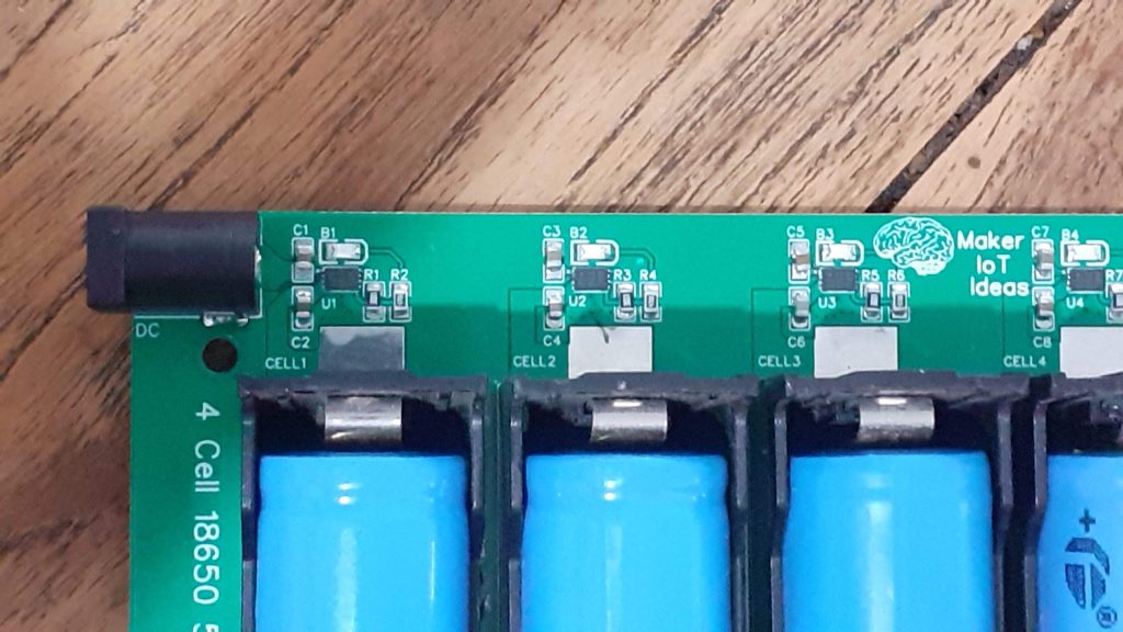
The MCP73832 from MICROCHIP seemed like a good choice for a custom design, as it requires only 5 additional external components, which are only two resistors, two capacitors and an led. The chip is also extremely low-cost.

  • High accuracy preset output voltage regulation (+/-0.75%)
  • Output voltage options include 4.2V, 4.35V, 4.4V and 4.5V
  • User-programmable charge current
  • Open-drain status output
  • On-chip thermal regulation
  • Preconditioning and end-of-charge ratio options
  • Under-voltage lockout

Includes integrated pass transistor, integrated current sensing, and reverse discharge protection in 5-pin SOT-23 and thermally-efficient 8-pin 2mm x 3mm DFN packages.

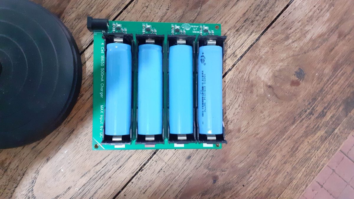
The Prototype Module


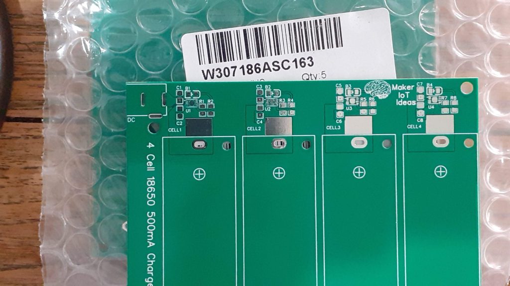
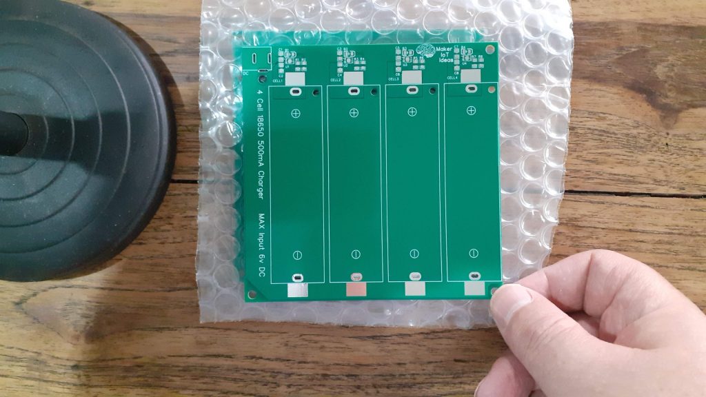
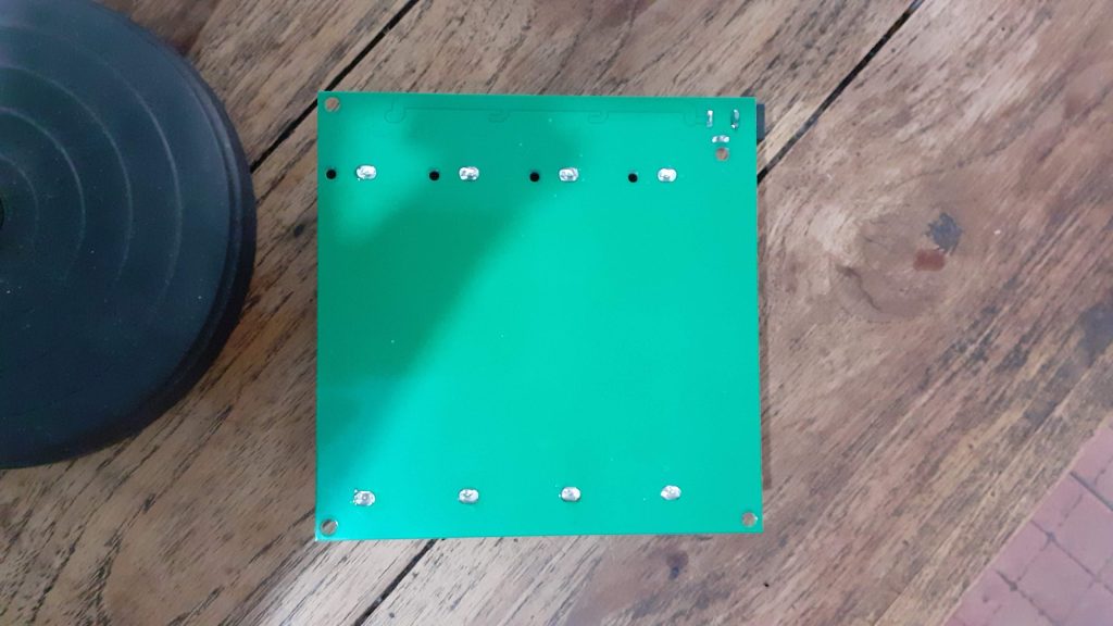
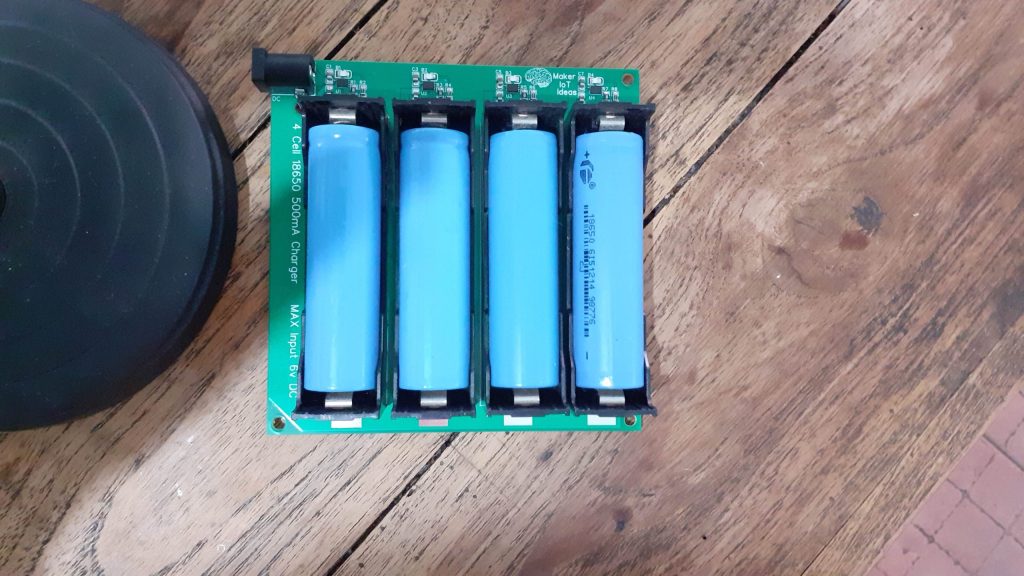
The design that I came up with, can charge 4-cell simultaneously. The maximum input voltage is limited to 6v DC.


Another interesting feature is the ability to use either through-hole battery holders or SMD ones. I did that because I have quite a few of the through-hole ones in stock, but as they were bought quite a while ago, the exact part number went on holiday. When having the module assembled in the factory,the SMD parts can be used, as there seems to be plenty in stock.

The Schematic

Because I enjoy a challenge, the design uses the smaller 3mm 2mm DFN8 package. Charging current is set with R9, which is 2k in this case, which will result in a charging current of the full 500mA. You can adjust it as per your requirements, to a value between 2k and 10k, as per the datasheet.

The full schematic is available here:

PCB Design

The PCB design was optimised to fit on a 10cm x 10cm board. Most of the board is made up of a solid copper pour to provide a good ground plane. Charging circuitry is placed as close together as possible, with a good connection of the thermal pad on the DFN8 package to the ground plane to help with thermal regulation. In this case, I have attempted to replicate the suggested reference design as closely as possible, while adapting it for use with the DFN8 package (Reference design uses the 5 lead SOT-23 package)


As seen in the close-up, components are placed as close as possible to the MCP73832, and via stitching are used to ensure a good connection to the ground, as well as allow the ground plane to serve as a heatsink.

Manufacturing

I choose PCBWay for my PCB manufacturing. Why? What makes them different from the rest?

PCBWay‘s business goal is to be the most professional PCB manufacturer for prototyping and low-volume production work in the world. With more than a decade in the business, they are committed to meeting the needs of their customers from different industries in terms of quality, delivery, cost-effectiveness and any other demanding requests. As one of the most experienced PCB manufacturers and SMT Assemblers in China, they pride themselves to be our (the Makers) best business partners, as well as good friends in every aspect of our PCB manufacturing needs. They strive to make our R&D work easy and hassle-free.

How do they do that?

PCBWay is NOT a broker. That means that they do all manufacturing and assembly themselves, cutting out all the middlemen, and saving us money.

PCBWay’s online quoting system gives a very detailed and accurate picture of all costs upfront, including components and assembly costs. This saves a lot of time and hassle.

PCBWay gives you one-on-one customer support, that answers you in 5 minutes ( from the Website chat ), or by email within a few hours ( from your personal account manager). Issues are really resolved very quickly, not that there are many anyway, but, as we are all human, it is nice to know that when a gremlin rears its head, you have someone to talk to that will do his/her best to resolve your issue as soon as possible.

Find out more here

Assembly

Assembly of this module definitely requires the use of a stencil. The DFN-8 package of the IC is only 3mm x 2mm, and there are 8 leads as well as a thermal pad crammed in there. A stencil will ensure that you add just the correct amount of solder paste to each pad.


As we can clearly see in this cropped picture of the stencil, those pads are SUPER tiny.

I chose to use the hotplate, as well as some hot air for the SMD component assembly. The battery holders and DC barrel-connector are all through-hole, and were thus assembled using a standard soldering iron, with slightly thicker solder, and a bit more heat than normal, as the pads are quite big, and the big copper pour really sucks the heat away from the joints.

Testing

Testing the module went really well. I used four 18650 cells that needed recharging, and they were very quickly ( in about 1 hour ) charged to 4.20 volt.

The Charge Indicator LED on each charging circuit works in reverse from what we would normally expect, with it lighting up while charging, and going out when done.

The current draw (measured on the bench power supply) verified that each cell was charging at the 500mA as designed. The current draw also reduced as each cell charging cycle completed and eventually went down to very close to zero (The Ampere meter on my bench supply can not measure very low current with a lof of accuracy -:) )

Measuring each cell that have completed its charging cycle with a standard multimeter confirmed that they were indeed at 4.20v, and that the charging circuitry was no longer feeding current to any of them.

Drawing current out of a single cell (I used a set of clips ) to power a dummy load, resulted in an automatic recharge cycle being initiated once the cell voltage dropped past the set charging threshold.

It is however VERY important to note that this module is by NO means a balanced cell charger. It is a 4-way single cell charger that charges 4 cells independently from each other, at the same time. It is thus completely possible as well as probable that the four cells will/may be at slightly different voltages at the end of each respective charging cycle.
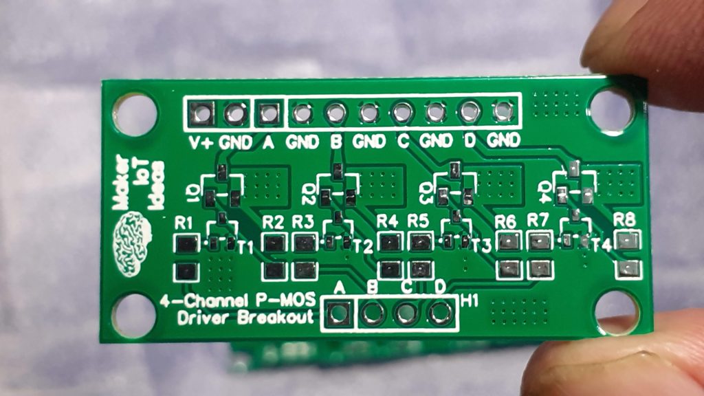
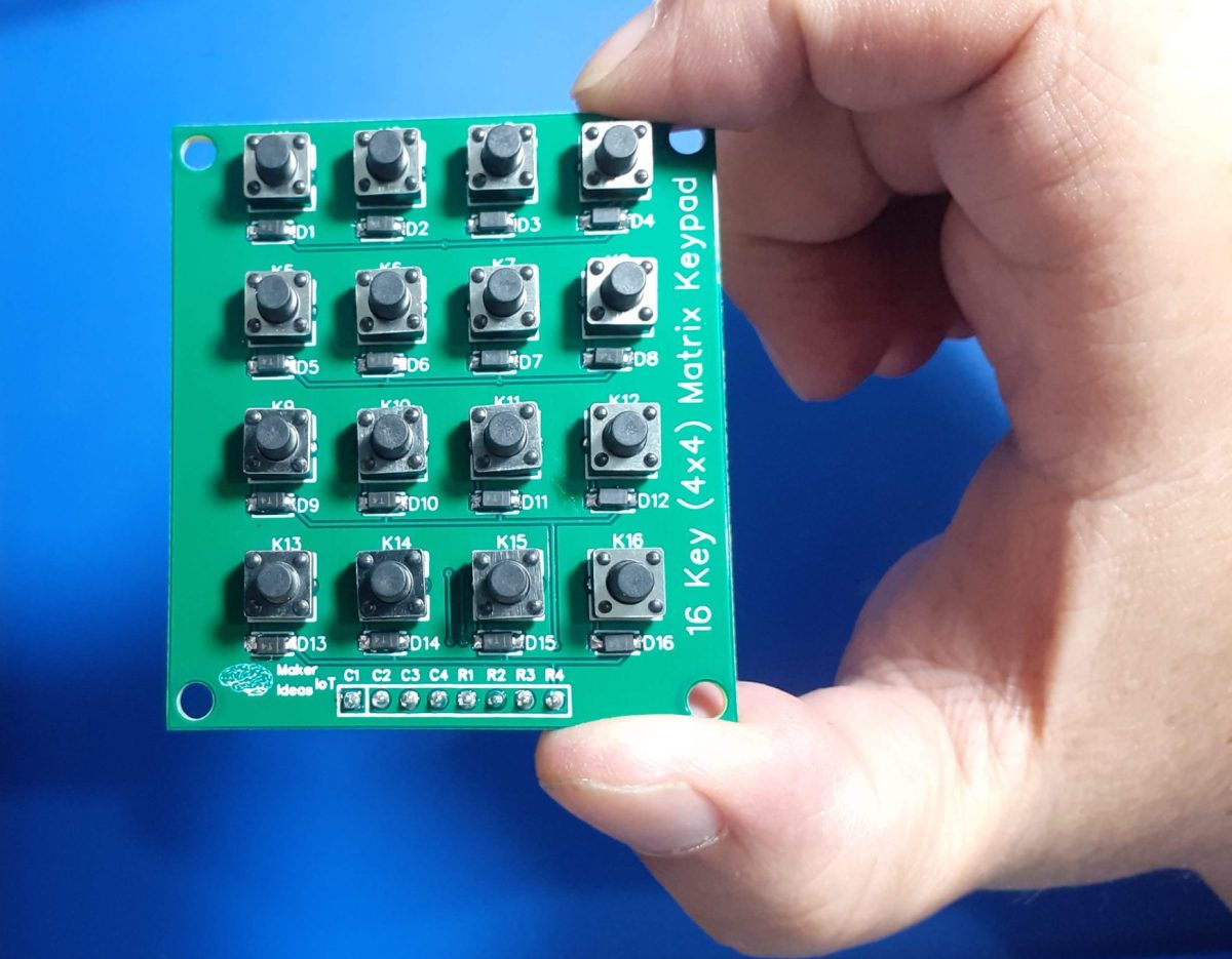
Conclusion

This project is most definitely high on the list of my most needed items. Keeping a bunch of 18650 cells charged and correctly maintained can be quite a chore, and the way that I have done it in the past was definitively not ideal.
It has also cost me quite a few cells that died way before their time.

Using this module, the chore of charging these cells will be reduced by a lot, and hopefully, in the future, I will come up with a solution to augment this module so that I can have these cells on a semi-permanent charge, with monitoring and only charging those cells that needs it.

Pictures