Build your own 8 DI Optically Isolated Arduino Shield – Part 3

Welcome to the final instalment of my 8 DI Optically Isolated Arduino Shield. Today I will show you some of the assembly pictures, as well as look at the coding to use this shield. I will also provide you with a link to the manufacturing files, in case you want to make your own.

These PBC’s were manufactured at PCBWAY.

You can order your own version of this board for just $5 USD if you click here

PCBWay makes it quite easy to order prototypes for your PCB’s… Just upload the Gerber files on their website, select your desired options for the PCB and order. The turn-around time is great. I received these boards, ordered together with a stencil for SMD assembly, in exactly 5 days, shipping from China to Thailand 🙂 That is super fast, as it arrived 4 days faster than the components that were ordered locally from Bangkok! Be sure to consider using their services next time you need a PBC made…

Top and bottom layout of completed Shield
Bottom of Shield
Top Layout

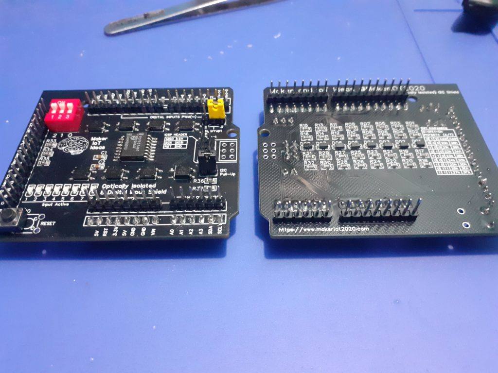
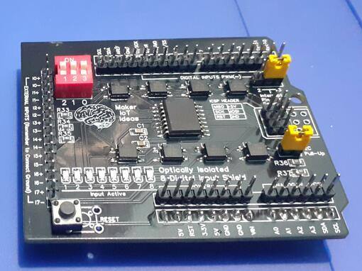
Some notes on assembly: The reset switch will seem misplaced, and indeed, it is 🙂 The reason for this is that I could not get any 4 pin tactile switches 🙁 So I had to either leave it unpopulated or use a two-pin tactile switch. As I will be using these shields myself, I decided that although it doesn’t look perfect, the two pin switch will still provide me with the functionality that I want.

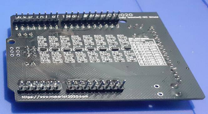
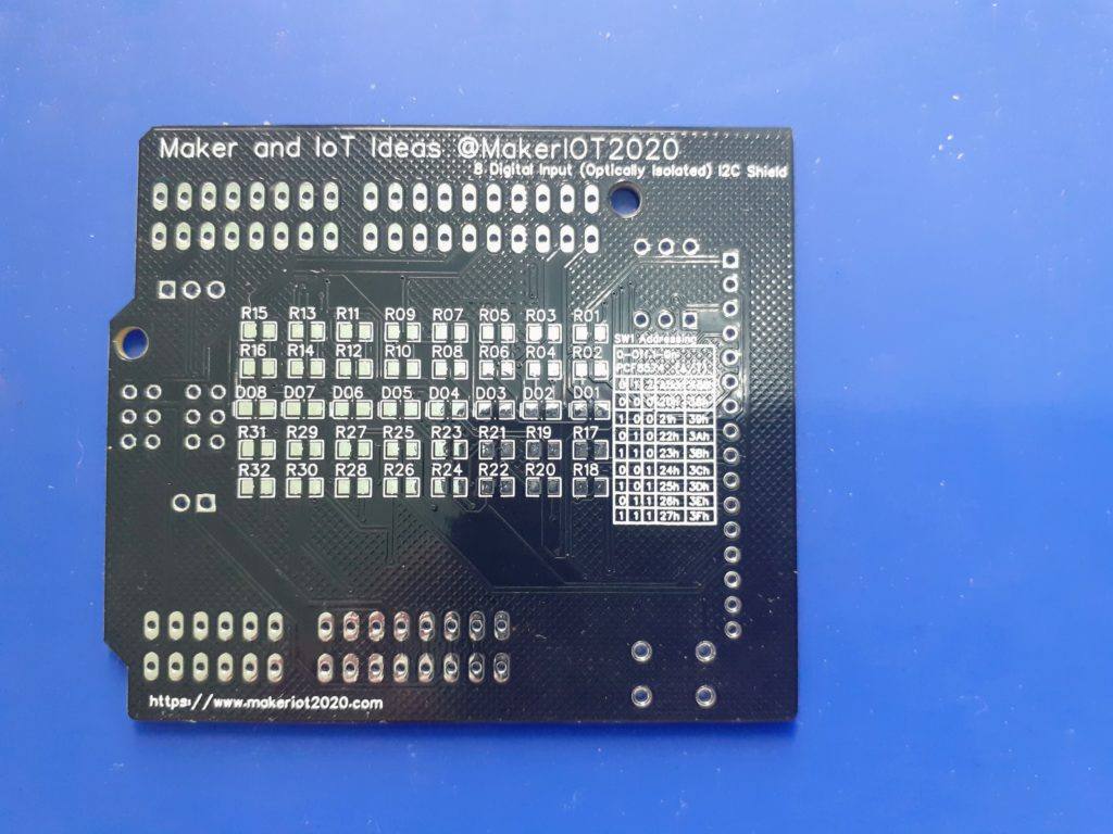
On the bottom of the board, you can still see some blobs of flux, as the pictures were taken right after assembly, and have not been cleaned up yet. Some solder joints have also not been cleaned up yet.

The top of the unpopulated PCB
The bottom of the PCB

Testing and Coding

The testing of the board is quite straightforward. I first checked all the power rails with a multimeter to make sure there are no open circuits of shorts. Then I checked connections to all the chips and other components, yes, it takes a while to do that, but rather safe than sorry. After assembly, I repeated this process, making sure that all the components receive the correct power level, and that all switches ( like for addressing and the reset button ) actually do what I intended them to do. The next tests were the individual inputs with the optocouplers. This is done by connecting an input source (between 5.5v and 32v) to each individual input and then physically testing on the pins of the optocoupler in question, for the correct voltage input.

The shield is then powered from 5v and the input test is repeated while checking with a multimeter that the input signal does indeed get transferred by the optocoupler to the PCF8574 chip. I found that with the particular batch of PCF8574 chips that I got, that the IC would only respond reliably with a voltage between 5.5v and 32v. The original design was for 3.0v to 32v. I found that the Optocoupler EL357N seems to be unable to switch itself on at the low current allowed through the resistor divider at the input. This can be fixed by lowering the value of R1, R5, R9, R13, R17, R21, R25, R27 from 4k7 to whatever value you need. Note that that will reduce the top-level input voltage that you can safely use. For my application, however, 5.5v to 24v will be perfect, so I will leave it as is.

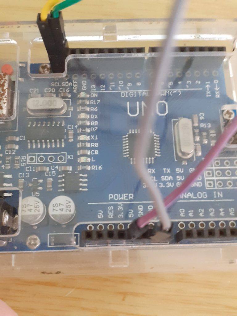
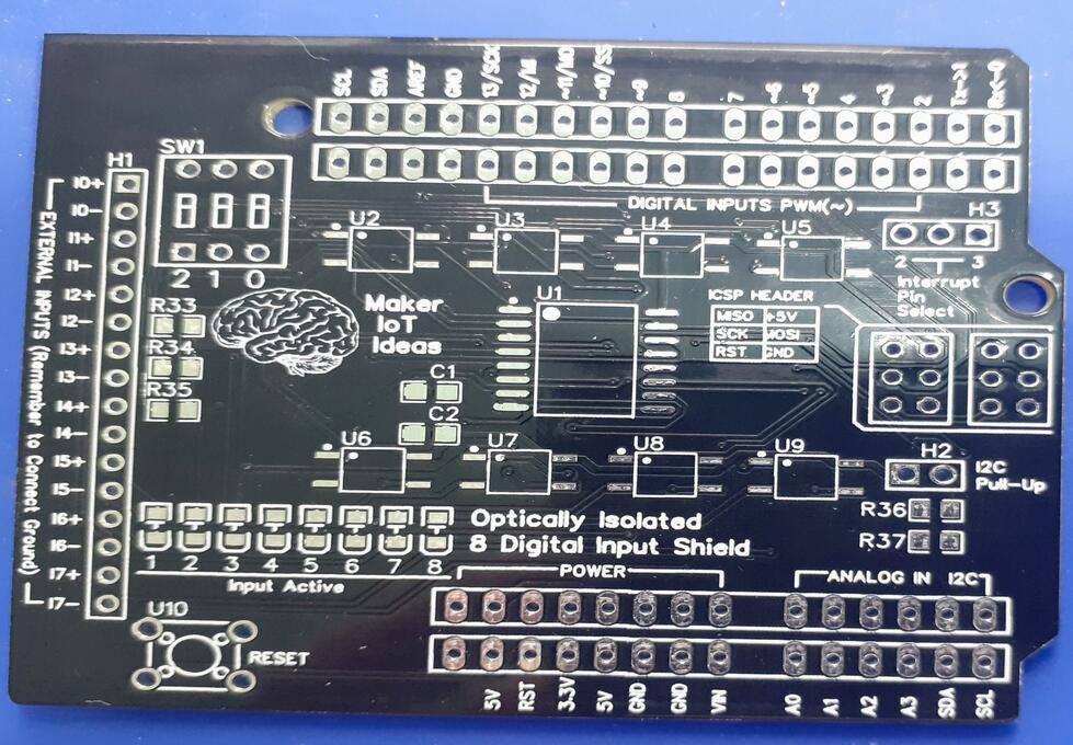
The shield is now connected to an Arduino with DuPont Wires, to test the I2C addressing of the PCF8574. The chip address is changed with the 3-way dip switch at SW1. All eight addresses are available. It should be noted that I have used a pull-up configuration on the address lines. That will reverse your logic.. Switching the dip switch on will pull the pin to GND, not to VCC as you would normally expect. Thus as an example, all switches off will give an address 0f 0x3f, while all on will give 0x38.

Coding

You can use the standard Arduino IDE with the Wire.h library to code the shield, or you can use one of the many PCF8574 libraries that are available. I coded my tests with the Embeetle IDE, as it gives me much better control over my code. I will show you a short, interrupt enabled sketch, in Arduino C++ below

#include <Wire.h>

byte _portStatus = 0b00000000;
boolean _readI2C = false;

void MyISR() { // Interrupt service routine
  //Serial.println("Interrupt Occured on Pin2");
  if (_readI2C != true) {
    _readI2C = true;  
  }
}

void setup() {
  // put your setup code here, to run once:
  pinMode(2,INPUT_PULLUP);
  attachInterrupt(digitalPinToInterrupt(2),MyISR,FALLING);
  Serial.begin(115200);
  Wire.begin();
  Wire.beginTransmission(0x20);
  Wire.write(0xFF); // set all pins to 1, needed to make them inputs
  Wire.endTransmission();
}

void loop() {
  // put your main code here, to run repeatedly:
  
  byte _data;
  if (_readI2C == true) {
    _readI2C = false;
    Wire.requestFrom(0x20,1);
    if (Wire.available()) {
      _data = Wire.read();
    }
  }
  if (_portStatus != _data) {
    Serial.print("Port Data Changed : 0xb");
    Serial.print(_portStatus,BIN);
    Serial.print(" changed to : 0xb");
    Serial.println(_data,BIN);
    _portStatus = _data;
    delay(50);
  } else {
    _portStatus = _portStatus;
  }
  
}

Conclusion

This turned out to be a very interesting and fun project to do. From designing the circuit to getting it manufactured and hand assembling it myself was a very satisfying experience. I would like to take this opportunity to thank Wendy Wu, from PCBWay‘s Marketing department, for her assistance with the manufacturing of the board. The speed and efficiency with which she handled this project were fantastic.

Multiple LoRa Device Communication

In this part of my LoRa Series ( Part 3 ) I will look at some basic code for the Heltec LoRa 32 V2 Module. This code will in particular be focused on Multiple device communication. It can easily adapted from the stock example (as provided below) to implement a custom addressing scheme.

LoRa Multiple Communications No Interrupt

#include "heltec.h"

#define BAND    433E6  //you can set band here directly,e.g. //868E6,915E6


String outgoing;              // outgoing message

byte localAddress = 0xBB;     // address of this device
byte destination = 0xFD;      // destination to send to

byte msgCount = 0;            // count of outgoing messages
long lastSendTime = 0;        // last send time
int interval = 2000;          // interval between sends

void setup()
{
   //WIFI Kit series V1 not support Vext control
  Heltec.begin(true /*DisplayEnable Enable*/, true /*Heltec.LoRa Enable*/, true /*Serial Enable*/, true /*PABOOST Enable*/, BAND /*long BAND*/);

  Serial.println("Heltec.LoRa Duplex");

 
}

void loop()
{
  if (millis() - lastSendTime > interval)
  {
    String message = "Hello there!";   // send a message
    sendMessage(message);
    Serial.println("Sending " + message);
    lastSendTime = millis();            // timestamp the message
    interval = random(2000) + 1000;    // 2-3 seconds
  }

  // parse for a packet, and call onReceive with the result:
  onReceive(LoRa.parsePacket());
}

void sendMessage(String outgoing)
{
  LoRa.beginPacket();                   // start packet
  LoRa.write(destination);              // add destination address
  LoRa.write(localAddress);             // add sender address
  LoRa.write(msgCount);                 // add message ID
  LoRa.write(outgoing.length());        // add payload length
  LoRa.print(outgoing);                 // add payload
  LoRa.endPacket();                     // finish packet and send it
  msgCount++;                           // increment message ID
}

void onReceive(int packetSize)
{
  if (packetSize == 0) return;          // if there's no packet, return

  // read packet header bytes:
  int recipient = LoRa.read();          // recipient address
  byte sender = LoRa.read();            // sender address
  byte incomingMsgId = LoRa.read();     // incoming msg ID
  byte incomingLength = LoRa.read();    // incoming msg length

  String incoming = "";

  while (LoRa.available())
  {
    incoming += (char)LoRa.read();
  }

  if (incomingLength != incoming.length())
  {   // check length for error
    Serial.println("error: message length does not match length");
    return;                             // skip rest of function
  }

  // if the recipient isn't this device or broadcast,
  if (recipient != localAddress && recipient != 0xFF) {
    Serial.println("This message is not for me.");
    return;                             // skip rest of function
  }

  // if message is for this device, or broadcast, print details:
  Serial.println("Received from: 0x" + String(sender, HEX));
  Serial.println("Sent to: 0x" + String(recipient, HEX));
  Serial.println("Message ID: " + String(incomingMsgId));
  Serial.println("Message length: " + String(incomingLength));
  Serial.println("Message: " + incoming);
  Serial.println("RSSI: " + String(LoRa.packetRssi()));
  Serial.println();
}

LoRa Multiple communication, Interrupt

#include "heltec.h"

#define BAND    433E6  //you can set band here directly,e.g. 868E6,915E6

  
byte localAddress = 0xBB;     // address of this device
byte destination = 0xFF;      // destination to send to

String outgoing;              // outgoing message
byte msgCount = 0;            // count of outgoing messages
long lastSendTime = 0;        // last send time
int interval = 2000;          // interval between sends

void setup()
{
   //WIFI Kit series V1 not support Vext control
  Heltec.begin(true /*DisplayEnable Enable*/, true /*Heltec.LoRa Disable*/, true /*Serial Enable*/, true /*PABOOST Enable*/, BAND /*long BAND*/);

  LoRa.onReceive(onReceive);
  LoRa.receive();
  Serial.println("Heltec.LoRa init succeeded.");
}

void loop()
{
  if (millis() - lastSendTime > interval)
  {
    String message = "Hello World!";   // send a message
    sendMessage(message);
    Serial.println("Sending " + message);
    lastSendTime = millis();            // timestamp the message
    interval = random(2000) + 1000;     // 2-3 seconds
    LoRa.receive();                     // go back into receive mode
  }
}

void sendMessage(String outgoing)
{
  LoRa.beginPacket();                   // start packet
  LoRa.write(destination);              // add destination address
  LoRa.write(localAddress);             // add sender address
  LoRa.write(msgCount);                 // add message ID
  LoRa.write(outgoing.length());        // add payload length
  LoRa.print(outgoing);                 // add payload
  LoRa.endPacket();                     // finish packet and send it
  msgCount++;                           // increment message ID
}

void onReceive(int packetSize)
{
  if (packetSize == 0) return;          // if there's no packet, return

  // read packet header bytes:
  int recipient = LoRa.read();          // recipient address
  byte sender = LoRa.read();            // sender address
  byte incomingMsgId = LoRa.read();     // incoming msg ID
  byte incomingLength = LoRa.read();    // incoming msg length

  String incoming = "";                 // payload of packet

  while (LoRa.available())             // can't use readString() in callback
  {
    incoming += (char)LoRa.read();      // add bytes one by one
  }

  if (incomingLength != incoming.length())   // check length for error
  {
    Serial.println("error: message length does not match length");
    return;                             // skip rest of function
  }

  // if the recipient isn't this device or broadcast,
  if (recipient != localAddress && recipient != 0xFF)
  {
    Serial.println("This message is not for me.");
    return;                             // skip rest of function
  }

  // if message is for this device, or broadcast, print details:
  Serial.println("Received from: 0x" + String(sender, HEX));
  Serial.println("Sent to: 0x" + String(recipient, HEX));
  Serial.println("Message ID: " + String(incomingMsgId));
  Serial.println("Message length: " + String(incomingLength));
  Serial.println("Message: " + incoming);
  Serial.println("RSSI: " + String(LoRa.packetRssi()));
  Serial.println();
}

What is LoRa?

Introduction

When designing IoT solutions, we all encounter the problem of connecting our device(s) to each other, either directly, or through the internet. In Urban areas, it is quite easy to use WiFi or even GSM to achieve this, but these solutions often come with additional costs in the form of subscriptions. Although it is possible to run your own WiFi network free of charge, you will soon run into issues with the range…

Enter LoRa (short for Long Range) Radio communication. LoRa is a radio technology derived from chirp spread spectrum technology. It uses an ISM band, meaning it is unregulated in most countries, if you use the correct frequency for your country, that is.

It is also extremely low power, making it ideal for use with battery-powered devices.
The technology is available in Node-to-Node, as well as Node-to -Gateway modes.

In this series, I will show you how to use a few of the existing LoRa Modules available on the market.

Ai-Tinker Ra-02 (Sx1278)

Ra-02 Lora Module, with spring antenna, by Ai-Tinker

This Module is conveniently broken-out onto a breakout board. It is sort of bread-board friendly (depending on the size of your bread-board) and is nicely labelled. It is also extremely cheap ( around $USD5 each, depending on where you buy from).

Caveats

There are quite a few important things that you should know about these modules before you start using them.

Disclaimer: The caveats listed below are by no means complete, or even valid. They are the result of experimentation by myself, with the intent to destroy a few modules, to see how hardy they are. Also take into mind, that living in SE Asia, it is quite common to buy something from a shop, where the seller has no or only a very limited idea of what he or she is selling, and are thus usually quite unable to provide any technical support.

To summarise: USE YOUR HEAD. If I did leave out something, it is quite possible that I forgot, or decided not to include it on purpose. This is a general guide, and you should ideally do your own research as well. That is the best way to learn.


1) Always connect an Antenna. This may seem like a logical one, but it is extremely important. The module is capable of quite a lot of transmission power, and operating it without an antenna will quickly damage the module, permanently.

2) ONLY use 3.3v, even on the control lines (the module uses SPI). This is quite important, as it is not very clearly stated by the suppliers, and will result in very short-lived component operation 😉 If you absolutely have to use 5v, use a level converter. (There are examples available on the internet, where they use this chip directly from an Arduino Uno. I can confirm that that approach does work, BUT, not for very long. I have purposely sacrificed a pair of transceiver modules so that you don’t have to. You can also adjust the SPI frequency, in the event that your level converter is not capable of running at a high SPI frequency.

3)Make sure that you connect ALL the ground pins on the device. This is another area that is not fully explained by the user manual and does “unexplainably” result in damaged modules.

4) Use short, good quality cables, and if possible, keep the module off the breadboard.
While testing the modules, I found that the usual DuPont wires, as everyone should know by now, are quite unreliable. Combine that with a bread-board that has seen its share of use,
and it is a definite recipe for headache 🙂

5) LoRa Antennas are polarised, make sure you have your antennas in the same orientation.
Although this will not prevent it from working over short distances, it makes sense to just do it correctly. Good RF practices never hurt anybody 🙂

Connecting to Arduino

A Note on Power:
It is important to power this module from a decent dedicated 3.3v power-supply.
The Arduino Uno does sometimes have a 3.3v regulator on-board. From my tests, it is however not always up to the task, as the module may spike up to 120mA when transmitting. It is thus also recommended to have a nice fat capacitor across the power lines (decoupling cap) to soak up any spikes.

As mentioned above, a level converter is mandatory for a 5v Arduino. You may do without it if you use a 3.3v Arduino, but once again, your mileage will vary 🙂

Both the transmitter and receiver uses the same connections, which are listed below:

LoRa SX1278 ModuleArduino Board
3.3V
GndGnd
En/NssD10
G0/DIO0D2
SCKD13
MISOD12
MOSID11
RSTD9
Connections to the Arduino from a LoRa RA-02 Module

Remember that you NEED a Level converter between the LoRa Module and the Arduino.

Software Library

The software library that we will use in our example is the excellent library from Sandeep Mistry. We will just include this into the Arduino IDE, and then use a slightly modified version of the examples for our experiment. It is also important to note that we will use Node-to Node communication, NOT LoRaWan. This means that all your communications will essentially be unencrypted, and not addressed. This does however allow you the flexibility to design and implement your own addressing scheme.

LORA code for Transmitting Side

#include <SPI.h>
#include <LoRa.h>

int counter = 0;

void setup() {
  Serial.begin(115200);
  while (!Serial);

  Serial.println("LoRa Sender");

  if (!LoRa.begin(433E6)) { // Set the frequency to that of your  //module. Mine uses 433Mhz, thus I have set it to 433E6
    Serial.println("Starting LoRa failed!");
    while (1);
  }

  LoRa.setTxPower(20);
  
}

void loop() {
  Serial.print("Sending packet: ");
  Serial.println(counter);

  // send packet
  LoRa.beginPacket();
  LoRa.print("hello ");
  LoRa.print(counter);
  LoRa.endPacket();

  counter++;

  delay(5000);
}
LORA code for Receiver Side

#include <SPI.h>
#include <LoRa.h>

void setup() {
  Serial.begin(115200);
  while (!Serial);

  Serial.println("LoRa Receiver");

  if (!LoRa.begin(433E6)) {
    Serial.println("Starting LoRa failed!");
    while (1);
  }
}

void loop() {
  // try to parse packet
  int packetSize = LoRa.parsePacket();
  if (packetSize) {
    // received a packet
    Serial.print("Received packet '");

    // read packet
    while (LoRa.available()) {
      Serial.print((char)LoRa.read());
    }

    // print RSSI of packet
    Serial.print("' with RSSI ");
    Serial.println(LoRa.packetRssi());
  }
}

Where to from here?

If all went well, you will see packets being received in the serial monitor of the Arduino IDE, connected to the receiver module. You will also see that the data from this example is sent as a string… It is however also possible to send binary data, by using the LoRa.write() function.

In the next part of this series, I will show you how to use LoRa with the ESP32/ESP8266,
as well as a working example with binary data transmission and an addressing scheme in part 3.

Thank you

ESP32/ESP8266 WiFi Config and OTA on Demand

While working on a recent project, using a custom version of the ESP32, I had a particular need to be able to update the firmware of the device, as well as allow the end-user to set various configuration options on the device. This need can best be described as follows below:

1. The device firmware needs to be updated periodically, as new features are needed, or when bugs are discovered by the end-user, that needs fixing. The problem encountered was that the physical device will be quite far away from me, so travelling, or sending the device to and fro via post was not really an option.

Sending uncompiled firmware to the customer is a possibility, but also risky and prone to errors, as everyone is not always inclined to learn how to update firmware via USB port from an IDE, and accidental changes to code can render it unable to compile and upload in the first place.

The device also needs to run on battery power, in remote areas without connectivity. Conserving battery power is thus also a very important issue, one that prevents me from having a permanent OTA server running via WiFi.

2. The second issue was that there are certain setup parameters that needed to be set by the end-user, these include addresses and others. My initial thoughts were to implement a simple UI via UART, but that I also quickly saw that that, although very useable to me, would not appeal very much to an end-user.

These two issues, OTA and Configuration, both done through WiFi, seemed mutually exclusive as far as all the research that I have done online seemed to be concerned. To complicate it even further, the WiFi HAD to stay off when not in use.

I believe that I have developed a very neat, workable solution, that I would like to share with you today, in the hope that it will solve some problems for somebody out there, that maybe having a similar problem.

My solution makes use of a “flag” set in the ESP32/ESP8266 device’s EEPROM.
This “flag” can then be set to a “Normal” Run mode, a Firmware Update Mode, and a Configuration Mode.

Please Note: The code below has been tested, and works perfectly. You will however have to make modifications to use it for your own needs.

The code is also very long, so I will explain the operation here:

When first started, the chip will run your standard code.
When you quickly press the PGM button, 5 times after each other, a flag will be set to 0x0F.
This will then activate the ESP Soft IP.
You can then connect to this AP, and telnet to 192.168.4.1 on port 23

You will be presented with a very brief menu, where you can SET Firmware Mode, Exit or see the menu again.

This can be expanded to suit your needs

On setting Firmware Mode, the Flag 0xFF is written to EEPROM, and the ESP is restarted.
upon startup, you once more connect to the generated SoftIP, and then browse to http://192.168.4.1, log in with username admin, and password admin.

You can now load and upload a .bin firmware file to the ESP.
on successful upload, the flag 0x00 is once more written to EEPROM.

After restarting, the device will once more run your standard code.


Let us look at how I have done this:

The actual code will be commented with details, please read that for more info.

#include "EEPROM.h"
#include <WiFi.h>
#include <WiFiClient.h>
#include <WebServer.h>
#include <ESPmDNS.h>
#include <Update.h>

#define EEPROM_SIZE 64 // This can be smaller or larger, adjust to    //your needs as well as the chip capabilities
int wifi_ap_on = 0; // the address for the "flag"


// Wifi for Firmware Update and Configuration Server(s)
const char* host = "ESP32/8266";
char* ssid = "--- your desired ssid ---";
char* password = "--- your password ---";

// Define two types of Servers, they will however not run at the same // time
WebServer OTAserver(80); // OTA Server Port
WiFiServer ConfigServer(23); // Configuration Server Port

String header; // HTML requests will be stored in here

// HTML Pages for Firmware Updater
/*
 * These are the standard OTA examples that came with Arduino IDE
 * Modify and enhance as see fit, keeping in mind that my application
 * would not have access to the internet
 */

/*
 * Login page
 */
const char* loginIndex = 
 "<form name='loginForm'>"
    "<table width='20%' bgcolor='A09F9F' align='center'>"
        "<tr>"
            "<td colspan=2>"
                "<center><font size=4><b>ESP Firmware Update Page</b></font></center><br>"
                
                "<br>"
            "</td>"
            "<br>"
            "<br>"
        "</tr>"
        "<td>Username:</td>"
        "<td><input type='text' size=25 name='userid'><br></td>"
        "</tr>"
        "<br>"
        "<br>"
        "<tr>"
            "<td>Password:</td>"
            "<td><input type='Password' size=25 name='pwd'><br></td>"
            "<br>"
            "<br>"
        "</tr>"
        "<tr>"
            "<td><input type='submit' onclick='check(this.form)' value='Login'></td>"
        "</tr>"
    "</table>"
"</form>"
"<script>"
    "function check(form)"
    "{"
    "if(form.userid.value=='admin' && form.pwd.value=='admin')"
    "{"
    "window.open('/serverIndex')"
    "}"
    "else"
    "{"
    " alert('Error Password or Username')/*displays error message*/"
    "}"
    "}"
"</script>";

const char* serverIndex = "<form method='POST' action='/update' enctype='multipart/form-data'><input type='file' name='update'><input type='submit' value='Update'></form>";
// End HTML Pages 

// Other variables
int Btn = 0; // The PGM button, Usually connected to GPIO0
int wifi_ap = 0; // The Running MODE
int buttonState;
int buttonValue = 0;
int lastButtonState = LOW;
int buttoncount = 0;

void setup()
{
   Serial.begin(115200);
   EEPROM.begin(EEPROM_SIZE); initiate EEPROM
  /*
   * Upload the sketch via USB the first time, and let chip run for
   * a few seconds. We need to set the EEPROM location to a known
   * initial value. Then comment the following 3 lines, to prevent 
   * the chip from overwriting the EEPROM location on next startup
   */
  pinMode(Btn,INPUT);
  EEPROM.write(wifi_ap_on,0x00); // comment this line after first run
  EEPROM.commit();// comment this line after first run
  delay(50);// comment this line after first run
  wifi_ap = EEPROM.read(wifi_ap_on); // read EEPROM value into "flag"
  
  if (wifi_ap == 0x00) { 
   // This will be executed on normal startup
   // Place all your normal initialisation stuff here
   // For example other pin configurations and 
   // peripheral  initialisations
  } else if (wifi_ap == 0xFF) { // Firmware Update MODE
   // Setup for OTA Webserver.
   // I have used SoftAP mode, as internet would not
   // be available anyway.

    WiFi.softAP(ssid,password);
    IPAddress IP = WiFi.softAPIP();
    Serial.println("");
    Serial.print("Connected to ");
    Serial.println(ssid);
    Serial.print("IP address: ");
    Serial.println(WiFi.localIP()); 
     
    if (!MDNS.begin(host)) { //http://esp32.local
        Serial.println("Error setting up MDNS responder!");
        while (1) {
        delay(1000);
      }
    }

    
    server.on("/", HTTP_GET, []() {
    server.sendHeader("Connection", "close");
    server.send(200, "text/html", loginIndex);
  });
  server.on("/serverIndex", HTTP_GET, []() {
    server.sendHeader("Connection", "close");
    server.send(200, "text/html", serverIndex);
  });
  /*handling uploading firmware file */
  server.on("/update", HTTP_POST, []() {
    server.sendHeader("Connection", "close");
    server.send(200, "text/plain", (Update.hasError()) ? "FAIL" : "OK");
    ESP.restart();
  }, []() {
    HTTPUpload& upload = server.upload();
    if (upload.status == UPLOAD_FILE_START) {
      Serial.printf("Update: %s\n", upload.filename.c_str());
      if (!Update.begin(UPDATE_SIZE_UNKNOWN)) { //start with max available size
        Update.printError(Serial);
      }
    } else if (upload.status == UPLOAD_FILE_WRITE) {
      /* flashing firmware to ESP*/
      if (Update.write(upload.buf, upload.currentSize) != upload.currentSize) {
        Update.printError(Serial);
      }
    } else if (upload.status == UPLOAD_FILE_END) {
      if (Update.end(true)) { //true to set the size to the current progress

/*
 * NOTE : We clear the EEPROM Flag after a sucessful Firmware Update
 * That way, the chip will stay in OTA mode on a failure.
 */
        EEPROM.write(wifi_ap_on,0x00);
        EEPROM.commit();
        delay(5);
        Serial.printf("Update Success: %u\nRebooting...\n", upload.totalSize);
      } else {
        Update.printError(Serial);
      }
    }
  });
    OTAserver.begin();
  } else if (wifi_ap == 0x0F) { // End of Mode 0xFF 

    //This is Configuration Mode
    //This code will normally not be executed,
    //As the device exits Config mode on restart, and
    //We dont write Mode 0x0F to EEPROM

  } // End of Mode 0x0F
} // End of Void Setup

void loop() 
{
  CountButton(); // Count Button Presses
  if (buttoncount == 5) { // Activate Configuration Mode
    buttoncount = 0;
    StartSoftAP(); // Start a SoftAP
  }
  if (wifi_ap == 0x0F) { // Code for the Config Server (TELNET Style)
       WiFiClient client = ConfigServer.available(); // Start Config
       if (client) {
          String currentLine = "";
          client.println();
          client.println("Telnet Server - Welcome");
          client.println();
          client.println("Press <Enter> to Login");
          
    while (client.connected()) {
      if (client.available()) {
       char c = client.read();
       if (c == '\n') {
        if (currentLine.length() == 0) {
           
        } else {
          // Process Commands
       if (currentLine == "Master123abc") {
        telnetLogin == true;
        client.println();
        client.println();
        client.println("****** MENU ******");
          client.println();
          client.println("MENU -  SHOW THIS MENU");
          client.println("RUF  -  Enable Firmware Update Mode");
          client.println("EXIT -  Exit Menu and RESTART");
          client.println();
          client.print("Command> ");
          currentLine = "";
       }
       // Show MENU
       if (currentLine == "MENU") {
        client.println();
        client.println();
        client.println("****** MENU ******");
          client.println();
          client.println("MENU -  SHOW THIS MENU");
          client.println("RUF  -  Enable Firmware Update Mode");
          client.println("EXIT -  Exit Menu and RESTART");
          client.println();
          client.print("Command> ");
          
       }
 
       // EXIT AND RESTART
       if (currentLine == "EXIT") {
        client.println();
        client.println("Restarting in 5 Seconds");
        delay(5000);
        client.stop();
        ESP.restart();
      }
      // Upgrade Frmware Mode
      if (currentLine == "RUF") {
          client.println();
          client.println("Enable Firmware Update Mode");
          client.print("Connect to SoftAP :");
          client.println(ssid);
          client.println("Browse to http://192.168.4.1 ");
          client.println("Login with Username admin, Password admin");
          EEPROM.write(wifi_ap_on,0xFF); // Set Flag in EEPROM
          EEPROM.commit();
          delay(5000);
          client.stop();
          ESP.restart(); // Restart Device
      }
      
       // End Process commands 
           
          currentLine = ""; 
        }
        
       } else if (c != '\r') {
        currentLine += c;
       }  
        
      } // End if client Available
    } // End While Client Connected
    client.stop();
   } // END Client
  } // END MODE 0x0F
  if (wifi_ap == 0xFF) {
    OTAserver.handleClient(); // Handle OTA Server
    delay(1);
  }
  if (wifi_ap == 0x00 )
    // Normal code goes here , to be executed every cycle
  {

} // End of Void Loop

void StartSoftAP() // Start SoftAP, for Configuration Server
{
  WiFi.mode(WIFI_OFF);
  WiFi.softAP(ssid,password);
  IPAddress IP = WiFi.softAPIP();
  ConfigServer.begin();  
  wifi_ap = 0x0F; // Set Flag to Config Mode
                  // Note that we dont write it in EEPROM
}

void CountButton() // Counts Button Presses, to enable Config Mode
{
  //int buttonState;
  //int buttonValue = 0;
  //int lastButtonState = LOW;
  //int buttoncount = 0;
  //unsigned long lastDebounceTime = 0;
  //int debounceDelay = 50;
  buttonValue = digitalRead(Btn);
  if (buttonState != lastButtonState) {
    if (buttonValue == LOW) {
      buttoncount++;
      if (buttoncount > 10) buttoncount = 0;
    }
  }
  delay(50);
  lastButtonState = buttonValue;
  // End Debouncing
  if (buttoncount == 5) digitalWrite(LED,HIGH);
}

This concludes a very long piece of code, question are welcome.
Thank you

Using I2C with a 4×4 Matrix Keypad

Using a matrix keypad is a very easy way to add multiple control buttons to a project, be it to enter a password, or to control different devices. These keypads do unfortunately have some serious flaws (in my view anyway)

1) They are usually of extremely low quality ( especially some of the membrane types from China). This means they dont last very long.
2) A typical 4×4 Matrix keypad will require 8 of your precious IO pins for itself.

These two flaws can however easily be solved, if we use a bit of technology, and are willing to to a bit of simple circuit construction by ourselves.

What does this mean ? Most of us makers will inevitably have a piece of proto-board or strip-board lying around, as well as a few momentary push-button switches. These can easily be used to make out own, much more reliable keypad. Let us look at the circuit

Circuit diagram for a 4×4 Matrix Keypad

As we can see, to build a 4×4 matrix keypad, we will need 16 momentary switches. These are connected together as shown above. You can then interface it with your favourite micro-controller to read the key(s) pressed…

This definitely solves the first of my problems, but we still need 8 pins to control this keypad… or do we? No, we don’t, we need only 2 pins. That is to say if we use one of those PCF8574 I2C IO port expander modules. They are much more reliable, as well as quite cheap as well. all depending on where you buy them from, and how long you are willing to wait for shipping 🙂

Let us see how to connect the keypad to the I2C Module

a 4×4 Membrane Matrix Keypad with PCF8574 I2C port expander module
Connecting the two together, note that we do not connect the INT pin
Connect Power (VCC, GND and I2C lines
Connect to Arduino or your preferred microcontroller. We have used Arduino Uno, Note that you can also connect the I2C to A4 (SDA) and A5(SCL) if you prefer.

Now, we need to install some libraries

The first one is the actual Keypad library, you can download it from the link below

The second library that we will need, is the keypad_i2c library, once again, download it from the link below.

Coding the keypad


#include <Key.h>
#include <Keypad.h>
#include <Keypad_I2C.h>

#define I2CADDR 0x26 // Set the Address of the PCF8574

const byte ROWS = 4; // Set the number of Rows
const byte COLS = 4; // Set the number of Columns

// Set the Key at Use (4x4)
char keys [ROWS] [COLS] = {
  {'1', '2', '3', 'A'},
  {'4', '5', '6', 'B'},
  {'7', '8', '9', 'C'},
  {'*', '0', '#', 'D'}
};

// define active Pin (4x4)
byte rowPins [ROWS] = {0, 1, 2, 3}; // Connect to Keyboard Row Pin
byte colPins [COLS] = {4, 5, 6, 7}; // Connect to Pin column of keypad.

// makeKeymap (keys): Define Keymap
// rowPins:Set Pin to Keyboard Row
// colPins: Set Pin Column of Keypad
// ROWS: Set Number of Rows.
// COLS: Set the number of Columns
// I2CADDR: Set the Address for i2C
// PCF8574: Set the number IC
Keypad_I2C keypad (makeKeymap (keys), rowPins, colPins, ROWS, COLS, I2CADDR, PCF8574);

void setup () {
  Wire .begin (); // Call the connection Wire
  keypad.begin (makeKeymap (keys)); // Call the connection
  Serial.begin (9600);

}
void loop () {
 
  char key = keypad.getKey (); // Create a variable named key of type char to hold the characters pressed
 
  if (key) {// if the key variable contains
    Serial.println (key); // output characters from Serial Monitor
  }
}

Upload this to your Arduino device and enjoy. This sketch can also be adapted for 1×4, and 4×3 keypads, and with a little modification, will also work perfectly on ESP32 or ESP8266 as well…

ESP8266 and ESP32 AT Commands

NodeMCU V3, ESP8266

In this tutorial, I’ll show you some of the important and frequently used ESP8266 AT Commands or AT Instruction Set.  

ESP8266 WiFi Module offers complete networking solutions to our DIY (Do-it-yourself) and IoT (Internet of Things) projects. It provides WiFi connectivity to any microcontroller through its full TCP/IP Stack.

This means that you can use the ESP8266/ESP32 like a WiFi Modem, this is especially handy when you don’t want to reprogram an entire module for a project, or if you already have a working project on an Arduino type board, and just want to add WiFi connectivity to the project.


It is however important to tell you that it is sometimes better to write your own code to achieve exactly what you want. The AT Commands, in my opinion, is however extremely useful to quickly test something, or do a very simple integration. Your opinion and or milage will definitely vary on this one, feel free to comment and make suggestions as always 🙂

Kidbright 32, based on the ESP32 WROOM Chip

Let us get started then

Please NOTE:

The AT Command Set will ONLY function on a NEW ESP8266/ESP32 Module that you have not loaded custom firmware onto, OR on a module that you have re-flashed with the AT Command Firmware. This means that, If you have used the Arduino IDE to upload custom code to your ESP8266/ESP32 module, these commands will NOT work for you,
UNLESS you flash the module with ESPRESSIF AT Command Firmware!

The ESP8266 WiFi module and the microcontroller can be interfaced through the UART and with the help of a wide range of AT Commands, the Microcontroller can then control the ESP Module.

The AT Commands of the ESP8266 WiFi Module are responsible for controlling all the operations of the module like restarting, connecting to WiFi, changing the mode of operation and so forth.

Basically, the ESP8266 AT Commands can be classified into four types:

  • Test
  • Query
  • Set
  • Execute

In the following table, I will give you an example of the different types of AT Commands. I will use a sample command of “TEST” to demonstrate the differences between the different type of commands.

Command TypeCommand FormatCommand Function
TestAT+TEST=?Returns a value or a range of parameters
QueryAT+TEST?Returns the current value of a certain parameter
SetAT+TEST=parameter1, parameter2, …Set configuration of a certain parameter of group of parameters
ExecuteAT+TESTExecutes an action
Types of AT Commands for ESP8266 or ESP32

Test Commands: The Test AT Commands of ESP8266 WiFi Module are used to get the parameters of a command and their range.

Query Commands: The Query Commands returns the present value of the parameters of a command.

Set Commands: The Set Commands are used set the values of the parameters in the commands and also runs the commands.

Execute Commands: The Execute Commands will run the commands without parameters.  

NOTE: Not all of the ESP8266 AT Commands support all the four command types.

The ESP8266 AT Commands Set is divided into three categories. They are:

  • Basic AT Commands 
  • WiFi AT Commands 
  • TCP/IP AT Commands 

There are a total of 88 AT Commands for ESP8266 WiFi Module. We will however only look at a few of the most important ones.

If you want to know the details of all the ESP8266 AT Commands, then I suggest that you visit the official documentation page provided by Espressif Systems (the manufacturer of ESP8266EX SoC),  here.   

NOTE: The Parameters mentioned in [] are optional.

Basic ESP8266 AT Commands

As per the official documentation from Espressif Systems, there are a total of 23 Basic AT Commands.

Basic AT Commands
AT
AT+RST
AT+GMR

AT

This is the basic command that tests the AT start up i.e. if the AT System is working correctly or not. If the AT start up is successful, then the response is OK.

CommandResponse
ATOK

AT+RST

This command can be used to restart (reset) the ESP8266 WiFi Module.    

CommandResponse
AT+RSTOK

AT+GMR

This command is used to check the version information of the firmware and SDK. The response consists of three things: the AT Firmware version, the SDK version and the compilation time of the BIN file.

CommandResponse
AT+GMR<AT Version><SDK Version><Compile Time>OK

Other important Basic AT Commands: AT+GSLP, ATE and AT+UART.

WiFi AT Commands

The WiFi AT Commands are useful in controlling the WiFi features of the ESP8266 Module like setting up the WiFi Mode of operation, get the list of WiFi Networks, connect to a WiFi Network, setup the Access Point (AP), control DHCP, WPS, MAC Address, IP Address etc.

As per the official documentation, there are 40 WiFi AT Commands for ESP8266 Module. Let me introduce a few important AT Commands.

WiFi AT Commands
AT+CWMODE
AT+CWJAP
AT+CWLAP
AT+CWQAP
AT+CIPSTA
AT+CWSAP
AT+CWLIF

AT+CWMODE

This command is used to set the WiFi Mode of operation as either Station mode, Soft Access Point (AP) or a combination of Station and AP. The CWMODE command supports Test, Query and Set type commands.

The syntax, response and parameters (in Set command) of this command are given in the following table.

AT+CWMODE
Command TypeTestQuerySet
FormatAT+CWMODE=?AT+CWMODE?AT+CWMODE=<mode>
Response+CWMODE:<mode>OK+CWMODE:<mode> OKOK
Parameters<mode>1: Station2: Soft Access Point (AP)3: Station+SoftAP
Function Returns current WiFi ModeSets WiFi Mode
      

AT+CWLAP

This command lists out all the available WiFi Networks in the reach of ESP8266. It has both Set and Execute Command types.

AT+CWLAP
Command TypeSetExecute
FormatAT+CWLAP[=<ssid>,<mac>,<channel>,<scan_type>,<scan_time_min>,<scan_time_max>]AT+CWLAP
Response+CWLAP:<ecn>,<ssid>,<rssi>,<mac>,<channel>,<freq      offset>,<freq   cali>,<pairwise_cipher>,<group_cipher>,<bgn>,<wps>OK

NOTE: For more information on Parameters, please refer to the original documentation.

AT+CWJAP

This command is to connect to an Access Point (like a router).

AT+CWJAP
Command TypeQuerySet
FormatAT+CWJAP?AT+CWJAP=<ssid>,<pwd>[,<bssid>]
Response+CWJAP:<ssid>,<bssid>,<channel>,<rssi>OKOKor+CWJAP:<error>FAIL
Parameters<ssid>: SSID of the Access Point.<pwd>: Password.[<bssid>]: MAC Address of AP (usedwhen multiple APs have the same SSID.)<error>1: Connection timeout.2: Wrong password.3: Cannot find the target AP.4: Connection failed.

AT+CWQAP

This command is used to disconnect the ESP8266 from an Access Point.

CommandResponse
AT+CWQAPOK

AT+CIPSTA

This command is used to set a static IP Address to the ESP8266 WiFi Module in Station Mode. This command has both Query and Set type commands.

AT+CIPSTA
Command TypeQuerySet
FormatAT+CIPSTA?AT+CIPSTA=<ip>[,<gateway>,<netmask>]
Response+CIPSTA:<ip>+CIPSTA:<gateway>+CIPSTA:<netmask> OKOK
Parameters<ip>: IP Address<gateway>: Gateway<netmask>: Netmask
FunctionReturns the IP address, Gateway and Netmask.Sets IP Address, Gateway and Netmask.

AT+CWSAP

This command is used to configure the ESP8266 WiFi Module in Soft Access Point (AP) Mode. Both Query and Set types are available for this command.

AT+CWSAP
Command TypeQuerySet
FormatAT+CWSAP?AT+CWSAP =<ssid>,<pwd>,<chl>,<ecn>[,<maxconn>][,<ssid  hidden>]
Response+CWSAP:<ssid>,<pwd>,<chl>,<ecn>,<max conn>,<ssid hidden>OKorERROR
Parameter<ssid>: SSID of AP.<pwd>: Password.<chl>: Channel ID.<ecn>: Encryption method.0: OPEN2: WPA_PSK3: WPA2_PSK4: WPA_WPA2_PSK<max conn>: Max # of Stations<ssid hidden>:0: SSID is broadcasted. (default)1: SSID is not broadcasted.

AT+CWLIF

Using this command, you can get the IP addresses of Stations that are connected to ESP8266, which is configured in SoftAP Mode.

AT+CWLIF
Format (Execute Command)AT+CWLIF
Response<ip addr>,<mac>OK
Parameters<ip address>: IP Address of the Station<mac>: MAC Address of the station

TCP/IP AT Commands

The TCP/IP AT Commands are responsible for communication over the internet. There are a total of 25 TCP/IP AT Commands for ESP8266 WiFi Module. Some of the important ones are mentioned here.

TCP/IP Commands
AT+CIPSTATUS
AT+CIPSTART
AT+CIFSR
AT+CIPMUX
AT+CIPSERVER
AT+CIUPDATE

AT+CIPSTATUS

This TCP/IP AT Command of the ESP8266 WiFi Module get the information or status of the connection. Only the Execute type command is available.

AT+CIPSTATUS
Command TypeExecute
FormatAT+CIPSTATUS
ResponseSTATUS:<stat>+CIPSTATUS:<linkID>,<type>,<remoteIP>,<remoteport>,<localport>,<tetype>
Parameter<stat>:2: Connected to an AP and its IP is obtained.3: Created a TCP or UDP transmission.4: Disconnected.5: Does NOT connect.<linkID>: ID of the connection.<type>: “TCP” or “UDP”.<remoteIP>: Remote IP address.<remoteport>: Remote port number.<localport>: Local port number.<tetype>:0: Client.1: Server.

AT+CIPSTART

This AT Command is used to establish one of the three connections: TCP, UDP or SSL. Depending on the type of TCP Connection (single or multiple), the format of the Set command will vary.

AT+CIPSTART
Command TypeSet
FormatSingle TCP ConnectionMultiple TCP Connection
AT+CIPSTART=<type>,<remoteIP>,<remoteport>[,<TCPkeepalive>]AT+CIPSTART=<linkID>,<type>,<remoteIP>,<remoteport>[,<TCPkeepalive>]
ResponseOKorERROR(Response when TCP connection is already established:ALREADY CONNECTED)
Parameters<link    ID>: ID of connection.<type>: “TCP”, “UDP” or “SSL”.<remoteIP>: Remote IP address.<remoteport>: Remote port number.[<TCPkeepalive>]: detection time interval

NOTE: The above table shows command for only establishing the TCP Connection. For establishing UDP and SSL Connections, please refer to the official documentation.

AT+CIFSR

This AT Command is used to obtain the IP Address of the ESP8266 WiFi Module.

AT+CIFSR
Command TypeExecute
FormatAT+CIFSR
Response+CIFSR:APIP,<SoftAPIPaddress>+CIFSR:APMAC,<SoftAPMACaddress>+CIFSR:STAIP,<StationIPaddress>+CIFSR:STAMAC,<StationMACaddress>OK
Parameters<SoftAPIPaddress>: IP address of the ESP8266 SoftAP;<SoftAPMACaddress>: MAC address of the ESP8266 SoftAP<StationIPaddress>: IP address of the ESP8266 Station.<StationMACaddress>: MAC address of the ESP8266 Station

AT+CIPMUX

This AT Command is used to enable or disable multiple TCP Connections.

AT+CIPMUX
Command TypeQuerySet
FormatAT+CIPMUX?AT+CIPMUX=<mode>
Response+CIPMUX:<mode>OKOK
Parameters<mode>:0: Single connection1: Multiple connections

AT+CIPSERVER

This AT Command is used to create or delete a TCP Server.

AT+CIPSERVER
Command TypeSet
FormatAT+CIPSERVER=<mode>[,<port>]
ResponseOK
Parameters<mode>:0: Delete Server.1: Create Server.

NOTE: A TCP Server can be created only when AT+CIPMUX=1 i.e. multiple connections are enabled.

AT+CIUPDATE

This AT Command is used update the software through WiFi Connection i.e. for over the air (OTA) updates.

AT+CIUPDATE
Command TypeExecute
FormatAT+CIUPDATE
Response+CIPUPDATE:<n>OK
Parameters<n>:
1: Find the Server
2: Connect to the Server
3: Get the Software Version
4: Start Update

I have included a PDF file with the complete AT command Set for download below.