A RISC-V IoT Development Board

Most of us will not know about RISC-V, or have had access to a RISC-V Chip.
This will thus be truly one of the most difficult posts I have written, due to many factors…

To name a few of these:
– The learning curve is extremely steep because there is extremely limited information available on the chip
– I can not at the moment allowed to divulge any information on the chip used, as I have received a few “sneak-preview” modules, and the manufacturer, who shall also remain anonymous for now, has not released it to the public yet.
– Most of the information available on the BL-602 ( on which the chip is based) is in relation to the BL-IOT-SDK, or Apache NuttX, an RTOS for use with microcontrollers.
While the NuttX project has excellent documentation, it is written in a very technical style, and focused on very basic, very advanced or very specific things. This will hopefully be improved upon to make it more “new-end-user-that-is-learning” friendly in future.

As most of us can no doubt see, This post is quite a challenge. I will thus focus on the PCB I designed to use with the “mystery BL-602” chip, and provide a lot of links to where you can get information on Apache NuttX, as well as how to use it with the BL-602 in general.

Once the module has been officially released, I will do a followup-post, with specific documentation etc, which, although I have already got some of it in my possession, I can not release at the moment for ethical reasons.

I think it fair to tell you all this much, and , unintentionally, have to create anticipation on what and where etc… My apologies for that, but rules are rules, and secrets are meant to be kept, until told otherwise…

So, lets get started. Some links to get you started and show you where this is going…

Apache Nuttx is the RTOS that you will most likely have to use to do anything useful with the BL-602 chip, as well as other microcontrollers, notably the ESP32-S3 and some of the STM32 chips.

Bouffalo Labs are the people behind the BL-602, as well as the BL-IOT-SDK, which will also be quite useful in designing solutions around the BL-602

Run Rust on RISC-V Firmware will provide some excellent points to get started

LEE Lup Yuen seems to be the kind person who has written most of the extensive and useful documentation on NuttX and the BL-602, amongst others…

NuttX Incubator on Github is a very detailed source, also by Mr Lee Lup Yuen, that aims to get us started with the BL-602 and NuttX – This link is HIGHLY recommended!
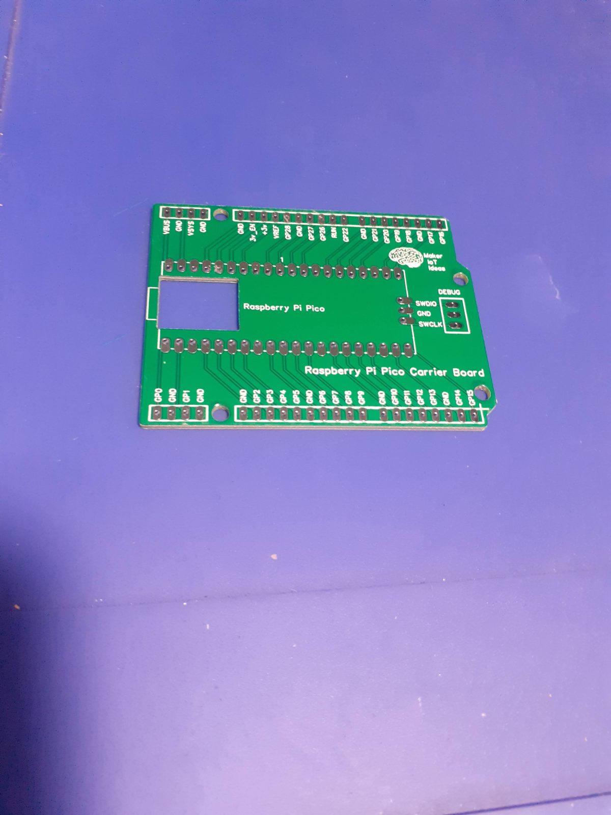
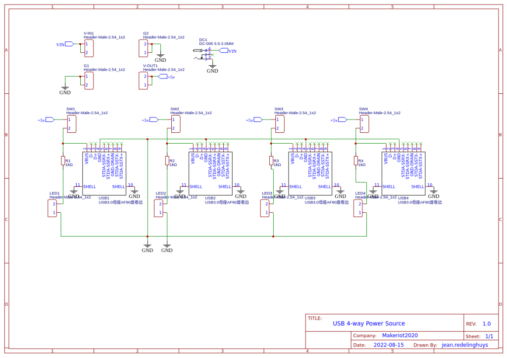
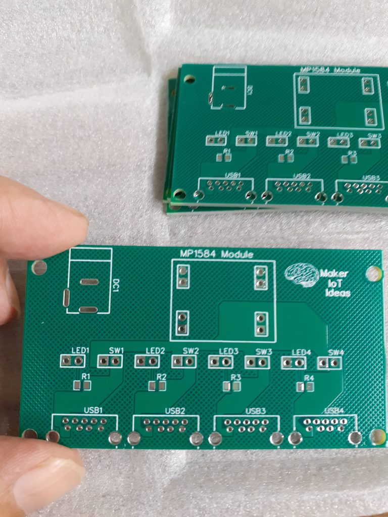
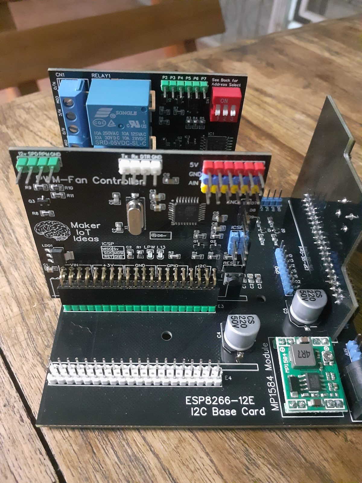
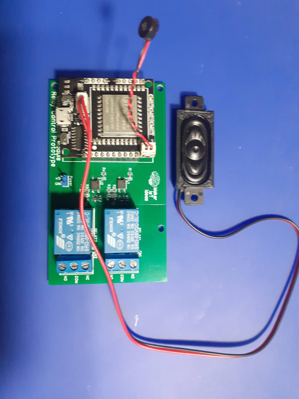
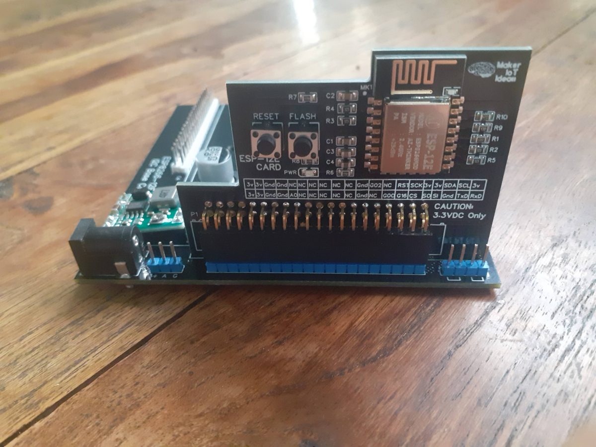
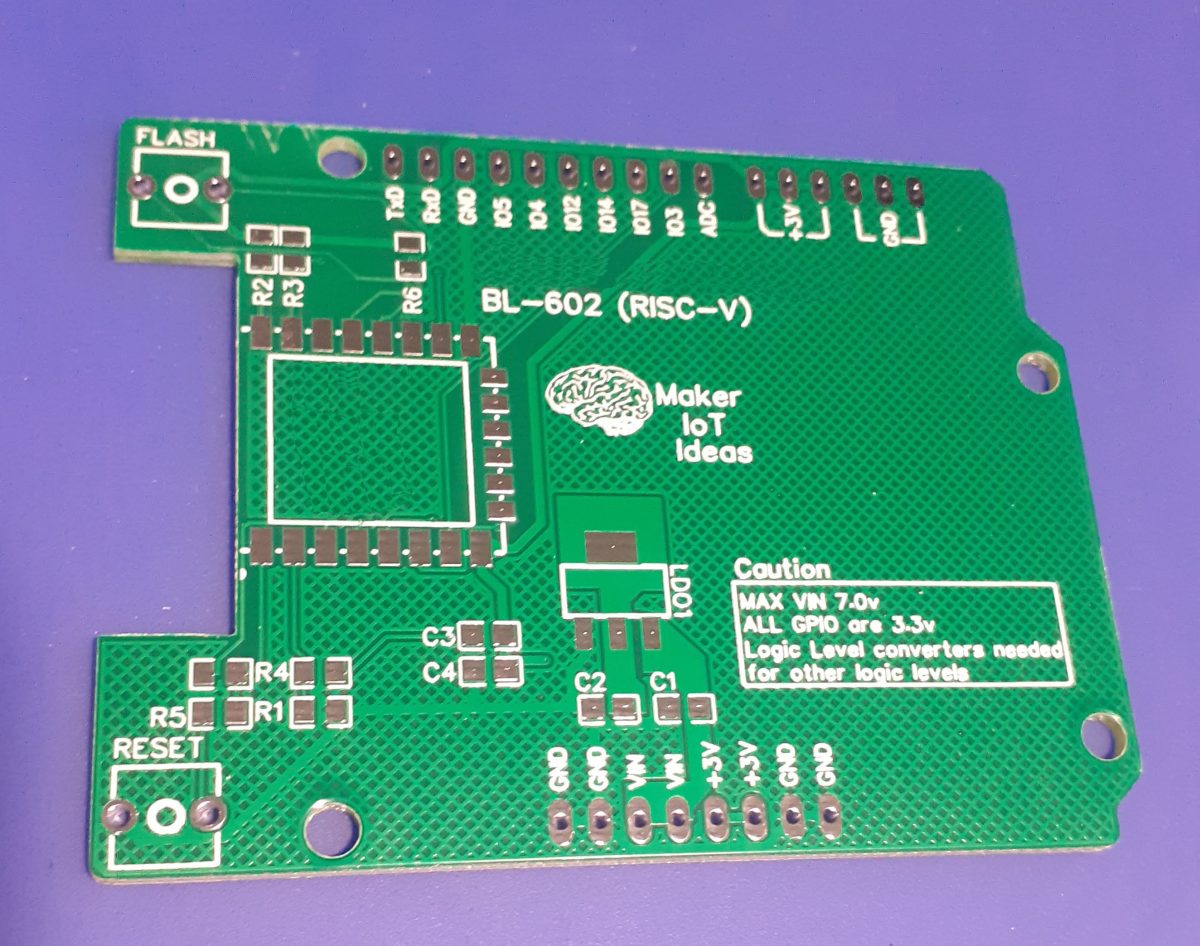
My Prototype PCB

Carrier PCB – Disclaimer – I have edited the silkscreen to remove Chip markings- This will be released to the public at a later stage. As mentioned above, it is necessary at this moment to keep this information confidential.

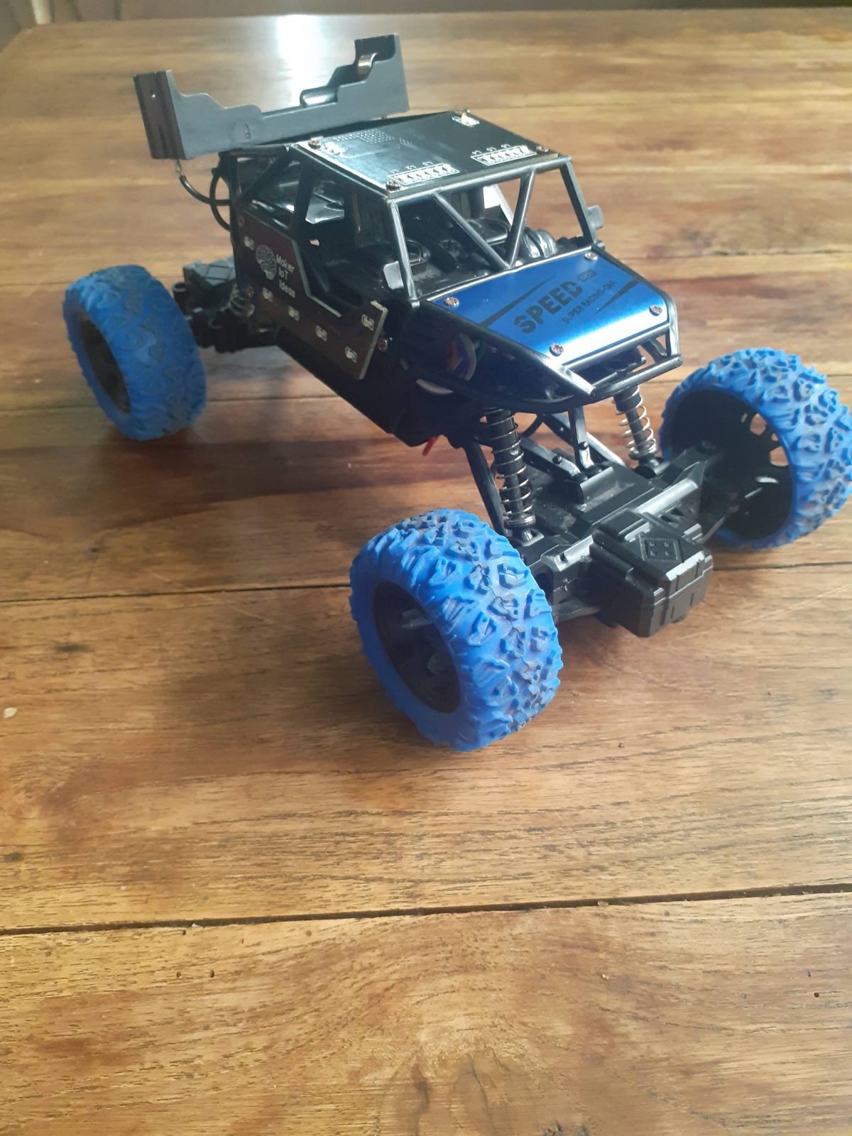
I decided to design an extremely basic, bare PCB with basically just the BL-602 chip and its supporting circuitry. This will allow me to focus only on the chip, as well as provide maximum flexibility in the future by the addition of add-on shields with specific functions. with this in mind, I purposely chose a PCB footprint similar to the Arduino UNO.

It is also worth mentioning that the chip module used on this PCB IS NOT a standard BL-602, although the footprint looks similar.

At the moment, I am however pulled between being frustrated at the lack of available information and also being excited at the possibilities that are already there or will open up in the future.

Needless to say, some people will be frustrated at the “seeming lack of details in this post”. Lets all stay calm, and remember that I will post a followup, with all the details soon.

Manufacturing

Over the past eight years, PCBWay has continuously upgraded their MANUFACTURING plants and equipment to meet higher quality requirements, and now THEY also provide OEM services to build your products from ideas to mass production and access to the market.


The PCB for this project has been manufactured at PCBWay.
Please consider supporting them if you would like your own copy of this PCB, or if you have any PCB of your own that you need to have manufactured.

PCBWay

If you would like to have PCBWAY manufacture one of your own, designs, or even this particular PCB, you need to do the following…
1) Click on this link
2) Create an account if you have not already got one of your own.
If you use the link above, you will also instantly receive a $5 USD coupon, which you can use on your first or any other order later. (Disclaimer: I will earn a small referral fee from PCBWay. This referral fee will not affect the cost of your order, nor will you pay any part thereof.)
3) Once you have gone to their website, and created an account, or login with your existing account,

4) Click on PCB Instant Quote

5) If you do not have any very special requirements for your PCB, click on Quick-order PCB

6) Click on Add Gerber File, and select your Gerber file(s) from your computer. Most of your PCB details will now be automatically selected, leaving you to only select the solder mask and silk-screen colour, as well as to remove the order number or not. You can of course fine-tune everything exactly as you want as well.

7) You can also select whether you want an SMD stencil, or have the board assembled after manufacturing. Please note that the assembly service, as well as the cost of your components, ARE NOT included in the initial quoted price. ( The quote will update depending on what options you select ).

8) When you are happy with the options that you have selected, you can click on the Save to Cart Button. From here on, you can go to the top of the screen, click on Cart, make any payment(s) or use any coupons that you have in your account.

Then just sit back and wait for your new PCB to be delivered to your door via the shipping company that you have selected during checkout.

RaspberryPi Pico Carrier PCB

The Rp2040 chip from the RaspberryPi foundation should be quite well known to everybody by now. Many companies have also released their own development boards based on it. The original Raspberry Pi Pico is popular, based on its small size.


For myself, there is however a serious drawback, its small size, while perfect for breadboard, made it necessary for the developers to place the pinouts on the back of the board. This makes it necessary to either memorise the pinouts or always have a pinout diagram handy when working with it.

The module also comes with castellated holes, making it ideal to place onto a custom PCB as a “component”. This got me thinking, I can easily design a custom RP2040-based PCB, but manually assembling the tiny RP2040 is something that my poor eyesight will make a bit challenging (staring at computer screens for many years does really take its toll as you get older).


Finding components in stock (excluding the RP2040) is also a challenge in my area.

This made me think about taking a popular footprint ( like the Arduino Uno ), and placing a Pico module directly onto the board, labelling all the pins clearly on the front, and installing female headers to access them.

While it is obviously not a very complicated PCB, it will definitely help me to utilise the fantastic little chip more effectively.

Assembling the PCB should only take a few minutes, as you only have to solder the pico and female header pins to the board. When completed, it should look like this:

If you have already soldered headers to your Pico, you can still use this PCB as well. You can also use the new Pico W with this board, the only difference is that the Pico W does not have castellated holes on the pins, so you would have to use header-pins. Also, the debug port now has a connector, so you will have to use the port directly on the Pico for that.

A good introduction to the new Pico-W can be found here. I have not bought any yet, so have no pictures to show, or comments to make on its operation.

What is next

I have plans to start designing a series of add-on shields with specific functions for this platform, since being freed from the breadboard, the Raspberry Pi Pico suddenly became much more interesting to me.

While smaller seems to be better in the electronics world of today, breadboarding, in my humble opinion, is quite aged, and can be extremely unreliable, due to poor connections etc. It is however very quick and fast, without requiring you to solder anything.

I am thus attempting to get the best of both worlds, by not being tied down to a breadboard, but with the freedom to go there if I choose, or just designing and using a custom shield of my choosing.

Manufacturing

Over the past eight years, PCBWay has continuously upgraded their MANUFACTURING plants and equipment to meet higher quality requirements, and now THEY also provide OEM services to build your products from ideas to mass production and access to the market.


The PCB for this project has been manufactured at PCBWay.
Please consider supporting them if you would like your own copy of this PCB, or if you have any PCB of your own that you need to have manufactured.

PCBWay

If you would like to have PCBWAY manufacture one of your own, designs, or even this particular PCB, you need to do the following…
1) Click on this link
2) Create an account if you have not already got one of your own.
If you use the link above, you will also instantly receive a $5 USD coupon, which you can use on your first or any other order later. (Disclaimer: I will earn a small referral fee from PCBWay. This referral fee will not affect the cost of your order, nor will you pay any part thereof.)
3) Once you have gone to their website, and created an account, or login with your existing account,

4) Click on PCB Instant Quote

5) If you do not have any very special requirements for your PCB, click on Quick-order PCB

6) Click on Add Gerber File, and select your Gerber file(s) from your computer. Most of your PCB details will now be automatically selected, leaving you to only select the solder mask and silk-screen colour, as well as to remove the order number or not. You can of course fine-tune everything exactly as you want as well.

7) You can also select whether you want an SMD stencil, or have the board assembled after manufacturing. Please note that the assembly service, as well as the cost of your components, ARE NOT included in the initial quoted price. ( The quote will update depending on what options you select ).

8) When you are happy with the options that you have selected, you can click on the Save to Cart Button. From here on, you can go to the top of the screen, click on Cart, make any payment(s) or use any coupons that you have in your account.

Then just sit back and wait for your new PCB to be delivered to your door via the shipping company that you have selected during checkout.

USB Power Supply Module

USB Ports are quite handy to power all our day-to-day electronic devices, but most charging devices are limited to a single port. While it is possible to get a commercial multi-port USB-Charger ( I have quite a few myself), they are usually limited in charging current or very cheaply made.

I decided to do my own, at this time limited to supplying power only, but with a few added features to make it my own.

Features

  • Individual switching of ports
  • Individual power LED indicator on each port, that can be left disconnected for total dark operation ( I don’t like charging lights in the bedroom )
  • Switchmode Power Supply unit, up to 2A output
  • Wide input supply options, not limited to 5v
  • Wide power tracks to ensure decent current transfer, and reduce heat generation on the PCB

Why did I choose to build my own?

We use USB ports on almost all our electronics devices, and most of the charging units that comes with these are quite badly designed. They are underpowered, have only one port, and have annoying lights that are quite bright at night.

I wanted a single unit that can accept up to 4 devices, control each port individually, as well as be relatively small and compact for travel use.

The PCB

The PCB is a double layer, with wide power tracks on opposite sides of the board. The component count is quite low, with only USB3 Type Female connectors(4), a single MP1584 Buck converter module, 4x current limiting resistors for the LED indicators, as well as male header pins for the switches and LED indicators.

The biggest challenge was to get the port spacing correct so that it will be easy to use all of them at the same time. CNC cutting the enclosure should also not be too difficult as well, once I get around to designing that in CAD/CAM

The Schematic

I have chosen to keep it simple on this revision, and only supply power via the ports. I plan to maybe do a full data-capable USB 3.0/ USB3.1 Hub later.

Manufacturing

Over the past eight years, PCBWay has continuously upgraded their MANUFACTURING plants and equipment to meet higher quality requirements, and now THEY also provide OEM services to build your products from ideas to mass production and access to the market.


The PCB for this project has been manufactured at PCBWay.
Please consider supporting them if you would like your own copy of this PCB, or if you have any PCB of your own that you need to have manufactured.

PCBWay

If you would like to have PCBWAY manufacture one of your own, designs, or even this particular PCB, you need to do the following…
1) Click on this link
2) Create an account if you have not already got one of your own.
If you use the link above, you will also instantly receive a $5 USD coupon, which you can use on your first or any other order later. (Disclaimer: I will earn a small referral fee from PCBWay. This referral fee will not affect the cost of your order, nor will you pay any part thereof.)
3) Once you have gone to their website, and created an account, or login with your existing account,

4) Click on PCB Instant Quote

5) If you do not have any very special requirements for your PCB, click on Quick-order PCB

6) Click on Add Gerber File, and select your Gerber file(s) from your computer. Most of your PCB details will now be automatically selected, leaving you to only select the solder mask and silk-screen colour, as well as to remove the order number or not. You can of course fine-tune everything exactly as you want as well.

7) You can also select whether you want an SMD stencil, or have the board assembled after manufacturing. Please note that the assembly service, as well as the cost of your components, ARE NOT included in the initial quoted price. ( The quote will update depending on what options you select ).

8) When you are happy with the options that you have selected, you can click on the Save to Cart Button. From here on, you can go to the top of the screen, click on Cart, make any payment(s) or use any coupons that you have in your account.

Then just sit back and wait for your new PCB to be delivered to your door via the shipping company that you have selected during checkout.

An SMD Breadboard

The electronics Breadboard is definitely one of those things that electronics hobbyists use quite a lot. It allows you to prototype your design relatively easily, with the use of breakout modules, wires and leaded components.

While this seems like a good thing, these breadboards are also unfortunately not perfect. The wires and connectors add electrical noise, and stray capacitance, as well as a certain level of unreliability.

My biggest issue with breadboards is not that though. it is the fact that you can only use through-hole components. Breakout PCBs is sort of a middle ground, as they allow you to connect SMD chips to stuff on a breadboard with wires, but that is not the issue here.

Doing a lot of prototyping, having a lot of components lying around, and then having to still try and find TH versions of everything to prototype with becomes costly in terms of time and space. If you have a larger project, but you are not yet at a stage to have a PCB made, adding another breadboard to the already cluttered setup is sometimes quite a challenge.

To get rid of this major point of frustration to me, I decided to try to solve it for myself by designing a SMD breadboard Hybrid.

What is on the board?

Quick Specifications

-300-hole solderable breadboard (dual layer, plated through-hole pads)
-64 0805 SMD pads, with plated through hole pads for connectors
-8 BJT/Mosfet footprint pads (SOT233/SOD23-3) with 3 plated through-hole pads per terminal
– 3 Power rails, 30 holes each for Vcc and Ground (Common ground on all)
– Mesh-style ground plane on both sides of the PCB.
– 4 mounting holes

Details

To address all of the various issues that I have with breadboarding, I did the following:

I hardly ever use more than a 300-hole breadboard for single stage of a project.
Many of these circuit blocks could benefit from being a permanent soldered solution, but does not warrant the time and expense to design a dedicated PCB to hold them.

The first thing to do was thus to design a 300-hole PCB breadboard, complete with top and bottom power rails.

My next issue was SMD components. Chips have many footprints, and to try and design for each of them would turn into a nightmare. Breakout PCB’s would thus still be used for those. My biggest issue was BJT’s Mosfets Capacitors, diodes and resistors.

These can be bought in lead versions, but that was exactly what I tried to get away from, so it needed some thinking.

Resistors, capacitors and diodes have only two terminals, and could thus easily be soldered onto 0805 resistor pads (depending of course on the capacitor size )

BJTs and Mosfets need their own footprint.

Each of the SMD components has a corresponding through-hole pad, to easily connect it to a different part of the board as needed. BJT’s and Mosfets have 3 per leg.

Hopefully this will make things a bit more organised in future, and save me some time;

Manufacturing

Over the past eight years, PCBWay has continuously upgraded their MANUFACTURING plants and equipment to meet higher quality requirements, and now THEY also provide OEM services to build your products from ideas to mass production and access to the market.


The PCB for this project has been manufactured at PCBWay.
Please consider supporting them if you would like your own copy of this PCB, or if you have any PCB of your own that you need to have manufactured.

PCBWay

If you would like to have PCBWAY manufacture one of your own, designs, or even this particular PCB, you need to do the following…
1) Click on this link
2) Create an account if you have not already got one of your own.
If you use the link above, you will also instantly receive a $5 USD coupon, which you can use on your first or any other order later. (Disclaimer: I will earn a small referral fee from PCBWay. This referral fee will not affect the cost of your order, nor will you pay any part thereof.)
3) Once you have gone to their website, and created an account, or login with your existing account,

4) Click on PCB Instant Quote

5) If you do not have any very special requirements for your PCB, click on Quick-order PCB

6) Click on Add Gerber File, and select your Gerber file(s) from your computer. Most of your PCB details will now be automatically selected, leaving you to only select the solder mask and silk-screen colour, as well as to remove the order number or not. You can of course fine-tune everything exactly as you want as well.

7) You can also select whether you want an SMD stencil, or have the board assembled after manufacturing. Please note that the assembly service, as well as the cost of your components, ARE NOT included in the initial quoted price. ( The quote will update depending on what options you select ).

8) When you are happy with the options that you have selected, you can click on the Save to Cart Button. From here on, you can go to the top of the screen, click on Cart, make any payment(s) or use any coupons that you have in your account.

Then just sit back and wait for your new PCB to be delivered to your door via the shipping company that you have selected during checkout.


PWM Controller with R/E

Last month I spent quite a lot of time on expansion modules for use with the ESP-12E I2C Base Card. While the system worked exceptionally well as a prototyping and firmware testing platform ( as originally intended ), I immediately saw that the physical size of everything ( base board, with the cards) would be a problem inside any enclosure, when used with a real-world project.

At the same time, I have an ongoing need to design and manufacture a device for a friend, that will have very limited space inside the enclosure due to other essential components.

I have thus decided to combine the functionality of two of the IO Expander cards into a more compact design, on a single PCB ( Which I plan to use to power and control an Air Assist blower on my desktop CNC/Laser cutter, as well as function as a next step prototype for my other project.

The PCB

Let us take a quick look at the PCB.

Starting from the top left, we have the Blower/Fan Header.
This supplies 12v DC to the Blower/Fan motor, as well as the PWM signal to control the speed. ( Level converted up from 5v DC to 12V, and then reduced to 3.3v ) This may seem strange.

Let me explain for some more clarity…
The PWM input on the Blower/Fan is internally pulled HIGH to 12v ( by the motor driver circuitry – I can not change that, as it is a commercial unit.) The datasheet however calls for a 0v to 3.3v PWM signal to control the speed.

There is also a further input from the fan, which is a pulsed speed indicator (Fan RPM). This signal is 5v.

Next to that header, is a UART Header, with Rx, Tx and DTR signals, with a ground. I do no longer add USB-to-UART chips to my designs because they are not used a lot, take up unnecessary space, and I tend to program with ICSP anyway.

On the right of that, (Red/Blue/Yellow Header) are 5v, Gnd and 6 Analog inputs(A0-A3, A6,A7) [A4 and A5 being used for I2C]

The ICSP programming header is below that,
with a jumper to select PCF8574 interrupt on Pin D2 or not

This is followed by 6 GPIO (P2-P7) from the IO Expander, and
additional GPIO (D10, D11, D12, D13) , as well as (D7,D8,D9) [To be used with a Rotary Encoder]

Another 6way Ground header, as well as the 12v input (red), follows.

Finally, we have J1 and J2, which will switch 12v through BSS138 Mosfets to control static speed 12v cooling Fans (Only one of these is PWM capable)


The 2 Relays are optically isolated from the controller and mains isolation cutouts are provided to further keep DC and AC voltages well away from each other. [ they really don’t play well together, don’t they ?]

This wraps up the quick PCB description.

Schematic

The Schematic is below, along with a download link ( zip format, with PNG image files)

Some more pictures

I use stencils with almost all of my SMD assembly. It saves a lot of time, makes for even solder paste application, and prevents the mess associated with applying solder paste with a syringe, or even worse a skewer-stick or something similar. They do cost extra though, but I find it well worthwhile in comparison to the mess and time that they save.

Manufacturing

Over the past eight years, PCBWay has continuously upgraded their MANUFACTURING plants and equipment to meet higher quality requirements, and now THEY also provide OEM services to build your products from ideas to mass production and access to the market.


The PCB for this project has been manufactured at PCBWay.
Please consider supporting them if you would like your own copy of this PCB, or if you have any PCB of your own that you need to have manufactured.

PCBWay

If you would like to have PCBWAY manufacture one of your own, designs, or even this particular PCB, you need to do the following…
1) Click on this link
2) Create an account if you have not already got one of your own.
If you use the link above, you will also instantly receive a $5 USD coupon, which you can use on your first or any other order later. (Disclaimer: I will earn a small referral fee from PCBWay. This referral fee will not affect the cost of your order, nor will you pay any part thereof.)
3) Once you have gone to their website, and created an account, or login with your existing account,

4) Click on PCB Instant Quote

5) If you do not have any very special requirements for your PCB, click on Quick-order PCB

6) Click on Add Gerber File, and select your Gerber file(s) from your computer. Most of your PCB details will now be automatically selected, leaving you to only select the solder mask and silk-screen colour, as well as to remove the order number or not. You can of course fine-tune everything exactly as you want as well.

7) You can also select whether you want an SMD stencil, or have the board assembled after manufacturing. Please note that the assembly service, as well as the cost of your components, ARE NOT included in the initial quoted price. ( The quote will update depending on what options you select ).

8) When you are happy with the options that you have selected, you can click on the Save to Cart Button. From here on, you can go to the top of the screen, click on Cart, make any payment(s) or use any coupons that you have in your account.

Then just sit back and wait for your new PCB to be delivered to your door via the shipping company that you have selected during checkout.

ATMega 328P Based PWM controller Card

As part of my recent ESP-12E I2C Base Board project, I designed an ATMega 328P Based PWM controller card, that can be used as an add-on card with the existing project, or standalone as a custom Arduino Nano compatible development board.

What is on the PCB?

The PWM controller card contains standard Arduino Nano circuitry running at 16MHz, without the USB to Serial converter, as well as a 3v to 5v level converter on the I2C port ( A4 and A5 ), as well as another 12v to 5v level converter, with a build in resistor-divider circuit, used to drive a 12v blower with 3.3v PWM control circuitry.

All analog inputs are broken out to make attaching additional sensors easier.

All the other unused GPIO pins are also broken out, either directly to headers on the PCB (D6~,D7,D8,D9~), D11,D12,D12 (ISCP Header) and D3 ( Marked RPM on the Fan Header)

Most of these pins are also additionally broken out onto the 2x20p female header at the bottom of the card ( See schematic for more details)

The board is designed to be powered from 12v DC (via the VIN pins on the 2x20p header) which is internally regulated down to 5v via an LDO voltage regulator.


External 3.3v should also be supplied to the 2x20Pin header to enable the I2C level converters on the same header. I2C is not directly broken out onto the PCB in this version of the PCB.

A reset button, and power led, as well as the standard led on D13 is also provided.

Manufacturing the PCB


Over the past eight years, PCBWay has continuously upgraded their MANUFACTURING plants and equipment to meet higher quality requirements, and now THEY also provide OEM services to build your products from ideas to mass production and access to the market.
https://vimeo.com/723212010


The PCB for this project has been manufactured at PCBWay.
Please consider supporting them if you would like your own copy of this PCB, or if you have any PCB of your own that you need to have manufactured.

PCBWay

If you would like to have PCBWAY manufacture one of your own, designs, or even this particular PCB, you need to do the following…
1) Click on this link
2) Create an account if you have not already got one of your own.
If you use the link above, you will also instantly receive a $5 USD coupon, which you can use on your first or any other order later. (Disclaimer: I will earn a small referral fee from PCBWay. This referral fee will not affect the cost of your order, nor will you pay any part thereof.)
3) Once you have gone to their website, and created an account, or login with your existing account,

4) Click on PCB Instant Quote

5) If you do not have any very special requirements for your PCB, click on Quick-order PCB

6) Click on Add Gerber File, and select your Gerber file(s) from your computer. Most of your PCB details will now be automatically selected, leaving you to only select the solder mask and silk-screen colour, as well as to remove the order number or not. You can of course fine-tune everything exactly as you want as well.

7) You can also select whether you want an SMD stencil, or have the board assembled after manufacturing. Please note that the assembly service, as well as the cost of your components, ARE NOT included in the initial quoted price. ( The quote will update depending on what options you select ).

8) When you are happy with the options that you have selected, you can click on the Save to Cart Button. From here on, you can go to the top of the screen, click on Cart, make any payment(s) or use any coupons that you have in your account.

Then just sit back and wait for your new PCB to be delivered to your door via the shipping company that you have selected during checkout.

VC-01 and VC-02 Offline Voice Module

In a recent article, I took a look at the new VC-01 and VC-02 Voice offline voice modules from AI-Thinker. I mentioned that I was working on a very simple prototype PCB to do some more tests, as well as make practical use of the module in real life.

In this very short post, I will show off the initial prototype that I came up with.
While I have to admit that it is still in an extremely basic stage, It is already definitely useful.

Part of the reason for this is that there is not a lot of information available on the VC-01 and VC-02 at this stage, as well as the fact that more exotic features like I2C and SPI are still not accessible in the current firmware. I thus had to work with what was available, as well as take into consideration what will work with the standard factory firmware as well.

The prototype carrier PCB will thus only have two optically isolated relays and their supporting circuitry. I intend to actually use the PCB in my EE LAb area to control some of the lights in the area.

The Schematic

The schematic shows the relay control circuitry, comprising of my standard optic isolator-based relay driver, as well as headers to accept the VC-01 or VC-02 offline voice module kit PCB.

Testing the PCB

The PCB was tested using the standard factory firmware, as well as my custom firmware, kindly provided by AI-Thinker. Below is a short video of that in action. Please note that the relays was not yet connected to any external devices at this stage.

Manufacturing the PCB


Over the past eight years, PCBWay has continuously upgraded their MANUFACTURING plants and equipment to meet higher quality requirements, and now THEY also provide OEM services to build your products from ideas to mass production and access to the market.


The PCB for this project has been manufactured at PCBWay.
Please consider supporting them if you would like your own copy of this PCB, or if you have any PCB of your own that you need to have manufactured.

PCBWay

If you would like to have PCBWAY manufacture one of your own, designs, or even this particular PCB, you need to do the following…
1) Click on this link
2) Create an account if you have not already got one of your own.
If you use the link above, you will also instantly receive a $5 USD coupon, which you can use on your first or any other order later. (Disclaimer: I will earn a small referral fee from PCBWay. This referral fee will not affect the cost of your order, nor will you pay any part thereof.)
3) Once you have gone to their website, and created an account, or login with your existing account,

4) Click on PCB Instant Quote

5) If you do not have any very special requirements for your PCB, click on Quick-order PCB

6) Click on Add Gerber File, and select your Gerber file(s) from your computer. Most of your PCB details will now be automatically selected, leaving you to only select the solder mask and silk-screen colour, as well as to remove the order number or not. You can of course fine-tune everything exactly as you want as well.

7) You can also select whether you want an SMD stencil, or have the board assembled after manufacturing. Please note that the assembly service, as well as the cost of your components, ARE NOT included in the initial quoted price. ( The quote will update depending on what options you select ).

8) When you are happy with the options that you have selected, you can click on the Save to Cart Button. From here on, you can go to the top of the screen, click on Cart, make any payment(s) or use any coupons that you have in your account.

Then just sit back and wait for your new PCB to be delivered to your door via the shipping company that you have selected during checkout.

ESP-12E Card

A few months ago, I started working on an MCU Card design, which borrows from the idea of a standard desktop PC, in which there are a main-board, MCU and expansion slots, to add and remove peripherals as needed quickly.

The ESP-12E Card is a continuation of that project, with the ultimate goal to have a universal “main-board” that can accept various MCUs and standardised “expansion modules” that perform a specific task.

ESP-12E Card
ESP-12E Card

The PCB

The ESP-12E Card contains the bare minimum components to allow the chip to function. There are no power regulators or USB-to-TTL converters onboard. Code is flashed via an external USB-to-TTL converter, with Flash and Reset buttons on the actual PCB, or available in the 2×20 Pin female header at the bottom of the card.

Most of the GPIO is also broken out to the 2×20 pin header, with the exception of the 6 GPIO that is usually connected to the internal Flash on the ESP-12E module.

I have made provision for enough power and ground pins on the header as well.

As far as GPIO is concerned, They have been grouped together by function, as much as possible at least, to make interfacing with the base-board as easy as possible.

The Schematic

ESP-12E Card Schematic

The schematic is not complicated. It is a standard ESP-8266 configuration, with all non-essential components removed.

The “base-board” ( a sneak preview )

Sneak preview of the Base Card

In a future article, I will tell you more about this ( for the time being limited to I2C ) base card. [ a quick explanation: When I mean limited to I2C, it relates to the fact that at the moment, the base card, ( a prototype ) can only communicate back to the MCU via I2C protocol from each of the expansion slots, as well as via two dedicated IRQ lines from each slot ]Power is supplied via a small SMPS module.

Manufacturing the PCB


Over the past eight years, PCBWay has continuously upgraded their MANUFACTURING plants and equipment to meet higher quality requirements, and now THEY also provide OEM services to build your products from ideas to mass production and access to the market.


The PCB for this project has been manufactured at PCBWay.
Please consider supporting them if you would like your own copy of this PCB, or if you have any PCB of your own that you need to have manufactured.

PCBWay

If you would like to have PCBWAY manufacture one of your own, designs, or even this particular PCB, you need to do the following…
1) Click on this link
2) Create an account if you have not already got one of your own.
If you use the link above, you will also instantly receive a $5 USD coupon, which you can use on your first or any other order later. (Disclaimer: I will earn a small referral fee from PCBWay. This referral fee will not affect the cost of your order, nor will you pay any part thereof.)
3) Once you have gone to their website, and created an account, or login with your existing account,

4) Click on PCB Instant Quote

5) If you do not have any very special requirements for your PCB, click on Quick-order PCB

6) Click on Add Gerber File, and select your Gerber file(s) from your computer. Most of your PCB details will now be automatically selected, leaving you to only select the solder mask and silk-screen colour, as well as to remove the order number or not. You can of course fine-tune everything exactly as you want as well.

7) You can also select whether you want an SMD stencil, or have the board assembled after manufacturing. Please note that the assembly service, as well as the cost of your components, ARE NOT included in the initial quoted price. ( The quote will update depending on what options you select ).

8) When you are happy with the options that you have selected, you can click on the Save to Cart Button. From here on, you can go to the top of the screen, click on Cart, make any payment(s) or use any coupons that you have in your account.

Then just sit back and wait for your new PCB to be delivered to your door via the shipping company that you have selected during checkout.

Robotic Toy Car – Part 5

In this almost post we look at the power distribution PCB for the almost completed Robotic Toy Car. I had many interesting issues to solve here, especially since I did not design my own Lipo battery charger circuit, but used a very useful little commercially available unit instead, the MH-CD42

Based on a relatively difficult chip to get information on, the module is basically an integrated Lipo charge/discharge module, with a built-in boost converter that provides 5v at a maximum of 2A current. What makes it special is the ability to simultaneously provide current and voltage, as well as charge the attached LiPo cell at the same time, when connected to an external charger.

It does, however, in my view at least, also have a few serious flaws, the most irritating of these being that it will completely discharge the attached LiPo cell even when completely switched off…

I have thus tried to stop this issue from occurring by adding a switch in line with the Lipo Cell, a quite obvious solution, but it should not have been needed if the chip functioned as intended… ( As far as I can gather, the module was originally designed to be used in USB power banks. This makes the flaw even more serious, as a self-discharging power bank really defeats the purpose)

Enough of that though, when it does work, it works great. just remember that you can not apply more than 5.5v DC to the charging input of the module.

The completed Power Distribution and charging module

The Schematic

There is actually not a lot going on here, as everything is already on the supplied module. I have just added a charging port, additional power headers for 5v output and ground, as well as direct access to the LiPo Cell output, and a switch header to cut off power to the MH-CD42 when it is not in use.

The PCB

The PCB was manufactured as a 2-layer FR-4 board. The entire top layer is used as a ground plane, and the bottom layer was used for the 5v and Vbat traces, which were made as big as possible to allow for the high current ( up to 2A ) that the unit can supply to a load.

The TOP later of the PCB is a complete ground plane.
The BOTTOM Layer caries only power traces for 5v and VBat
a 3D Render of the PCB, showing header pins and other connections

It is also worth mentioning that the VBAT pins are NOT 3.3v ( Remember that the LiPo cell can run from 4.2v down to 3.0v depending on the charge. These headers were only placed on the board to provide direct access to the LiPo cell, for use with for example an ADC input or for connection to a dev board that is already fitted with a buck converter or a suitable LDO voltage regulator.

The Actual PCB, as received from PCBWay
Top Layer of the PCB
Bottom Layer of PCB

Manufacturing the PCB


Over the past eight years, PCBWay has continuously upgraded their MANUFACTURING plants and equipment to meet higher quality requirements, and now THEY also provide OEM services to build your products from ideas to mass production and access to the market.

The PCB for this project has been manufactured at PCBWay.
Please consider supporting them if you would like your own copy of this PCB, or if you have any PCB of your own that you need to have manufactured.

PCBWay

If you would like to have PCBWAY manufacture one of your own, designs, or even this particular PCB, you need to do the following…
1) Click on this link
2) Create an account if you have not already got one of your own.
If you use the link above, you will also instantly receive a $5USD coupon, which you can use on your first or any other order later. (Disclaimer: I will earn a small referral fee from PCBWay. This referral fee will not affect the cost of your order, nor will you pay any part thereof.)
3) Once you have gone to their website, and created an account, or login with your existing account,

4) Click on PCB Instant Quote

5) If you do not have any very special requirements for your PCB, click on Quick-order PCB

6) Click on Add Gerber File, and select your Gerber file(s) from your computer. Most of your PCB details will now be automatically selected, leaving you to only select the solder mask and silk-screen colour, as well as to remove the order number or not. You can of course fine-tune everything exactly as you want as well.

7) You can also select whether you want an SMD stencil, or have the board assembled after manufacturing. Please note that the assembly service, as well as the cost of your components, ARE NOT included in the initial quoted price. ( The quote will update depending on what options you select ).

8) When you are happy with the options that you have selected, you can click on the Save to Cart Button. From here on, you can go to the top of the screen, click on Cart, make any payment(s) or use any coupons that you have in your account.

Then just sit back and wait for your new PCB to be delivered to your door via the shipping company that you have selected during checkout.

Robotic Toy Car – Part 4

In this part of the series, Robotic Toy Car – Part 4, We will add some custom side-panels to the project. While the original toy did come with some laser cut aluminum side panels, I decided to replace them with PCB versions, with even more flashing lights (yes, this thing is turning into a “Christmas tree” , but that is what the eventual owner wanted… )

These side-panels will not be programmable. They will simply be operated from a standard 555 timer and a couple of other components, to give a flash time of about one second on and off each…

It is also an excellent project to showcase the capabilities of PCBWay, in dealing with a “rather difficult” PCB to manufacture. As you may know by now, I use PCBWay‘s services quite extensively, and I also only design my PCB’s with EasyEDA. EasyEDA is however quite limited in some aspects, and as far as myself, making panels of different designs on one PCB with complex shapes is not something that I do every day…

Let us take a look at what had to be done, and how well it was manufactured…

The PCB Layout

What we have here, is basically two mirrored side-panels ( as far as the visible “outside” is concerned anyway ) That consists of 6 led’s per side that will flash alternatively. On the “inside” we have a 555 timer chip, with some resistors and capacitors, as well as transistors that does the switching.

The Schematic

The difficulty of this PCB is definitely in the manufacturing. I was however pleasantly surprised with the excellent work that was done by PCBWay. Their Engineering staff did contact me early on in the order, with a suggested plan to manufacture, and once I approved that, they very quickly went on to production. My initial concern was that they suggested “mouse-bites” which we all know can sometimes come out a bit strange…

Completed PCB in packaging..

I was however extremely pleased when the above parcel arrived… They added side rails, and the “mouse-bytes” were super tiny.

After assembly ( not cleaned up yet )
After Assembly ( not cleaned up yet )
Installed on the toy car body

The “almost completed ” Robotic Toy Car

With the completion of the side-panels, it was also time to start work on the power wiring and other essential components of the project, which will get their own detailed post in a few days.

the “almost completed” project

Some details on the construction:
The toy originally came with a single 500mA 14500 cell, which unfortunately stopped working very soon after only a few uses… This was however one of the reasons why the entire project happened in the first place, so no complaints there.

I decided to replace it with a 18560 cell with a capacity of about 1900mA. This cell is much bigger however, and I had to think of where to place it. I decided to put it on the roof, sort of emulating a “spoiler”.

Some of the next parts of the project will be the remote control unit, which will basically be an ESP8266 running ESP-Now protocol, as well as a decent battery charging and power distribution circuit, that will protect the Lipo cell from over charging and discharging, as well as provide sufficient power for all the added electronics in the toy car.

“But you said it was Robotic, so why have a remote control?”

The initial plan for the project did indeed say robotic, but it is also designed to be a learning platform, especially to teach coding. With that in mind, it is definitely better to keep things simple for now, and add sensors and more capabilities later on, especially as I am actually planning to replace the main MCU board with a more powerful ESP32 in a next version anyway.

The car body is also extremely cramped, and does not have any space for mounting sensors at all. I plan to remedy that by designing and 3d-printing a whole new custom body shell later… providing that my young friend actually stays interested enough to learn the coding… If he doesn’t, he will as least have a very interesting looking custom remote controlled toy car.

Manufacturing the PCB

The PCB for this project is currently on its way from China, after having been manufactured at PCBWay.
Please consider supporting them if you would like your own copy of this PCB, or if you have any PCB of your own that you need to be manufactured.

PCBWay

If you would like to have PCBWAY manufacture one of your own, designs, or even this particular PCB, you need to do the following…
1) Click on this link
2) Create an account if you have not already got one of your own.
If you use the link above, you will also instantly receive a $5USD coupon, which you can use on your first or any other order later. (Disclaimer: I will earn a small referral fee from PCBWay. This referral fee will not affect the cost of your order, nor will you pay any part thereof.)
3) Once you have gone to their website, and created an account, or login with your existing account,

4) Click on PCB Instant Quote

5) If you do not have any very special requirements for your PCB, click on Quick-order PCB

6) Click on Add Gerber File, and select your Gerber file(s) from your computer. Most of your PCB details will now be automatically selected, leaving you to only select the solder mask and silk-screen colour, as well as to remove the order number or not. You can of course fine-tune everything exactly as you want as well.

7) You can also select whether you want an SMD stencil, or have the board assembled after manufacturing. Please note that the assembly service, as well as the cost of your components, ARE NOT included in the initial quoted price. ( The quote will update depending on what options you select ).

8) When you are happy with the options that you have selected, you can click on the Save to Cart Button. From here on, you can go to the top of the screen, click on Cart, make any payment(s) or use any coupons that you have in your account.

Then just sit back and wait for your new PCB to be delivered to your door via the shipping company that you have selected during checkout.