In this post, I will tell you all the basics of the I2C protocol. What it is, where it comes from and also how it is configured and setup. We will also look at how data is transferred and received
Table of contents
1. Introduction
2. The Features of I2C
3. The Hardware
3.1 The physical I2C Bus
3.2 The Master and Slave devices on the bus
4. The data transfer protocol
4.1 The Start Condition
4.2 The Address Block
4.3 The Read/Write Bit
4.4 The ACK/NACK Bit
4.5 The Data Block
4.6 The Stop Condition
5. How does I2C work in practice
5.1 Sending data to a Slave Device
5.2 Reading data from a Slave Device
5.3 The Clock stretching concept
Introduction
I2C communication is the short form name for inter-integrated circuit protocol. It is a communication protocol developed by Philips Semiconductors for the transfer of data between a central processor and multiple integrated circuits on the same circuit board by using just two common wires.
Due to its simplicity, it is widely adopted for communication between microcontrollers and sensor arrays, displays, IoT devices, EEPROMs etc.
This is a synchronous serial communication protocol. It means that data bits are transferred one by one at regular intervals of time set by a reference clock line.
The Features of I2C
The I2C protocol has the following important features
- Only two common bus lines (wires) are required to control any device/IC on the I2C network.
- There is no need for a prior agreement on data transfer rate like in UART communications. The data transfer speed can thus be adjusted whenever it is required.
- It has a simple mechanism for validating the transferred data.
- It uses a 7-bit addressing system to target a specific device/IC on the I2C bus.
- I2C networks are extremely easy to scale. New devices can simply be connected to the two common I2C bus lines.
The Hardware
The physical I2C Bus
The I2C Bus (Interface wires) consists of just two wires and are named Serial Clock Line (SCL) and Serial Data Line (SDA). The data to be transferred is sent through the SDA wire and is synchronized with the clock signal from SCL. All the devices/ICs on the I2C network are connected to the same SCL and SDA lines as shown in the image below:
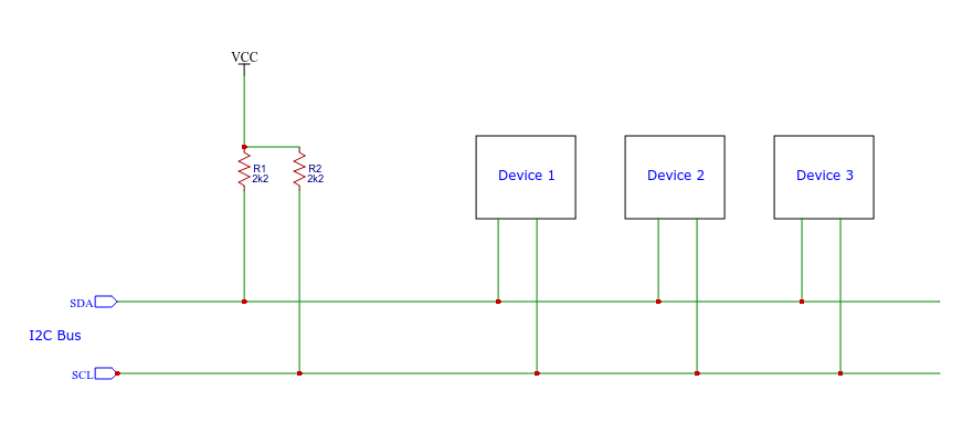
Both the I2C bus lines (SDA, SCL) are operated as in open-drain driver mode. It means that any device/IC on the I2C network can drive(pull) SDA and SCL low, but they cannot drive them high. So, a pull-up resistor is used on each bus line, to keep them high (at positive voltage) by default.
This is to prevent the bus from shorting, which might happen when one device tries to pull the line high and some other device tries to pull the line low.
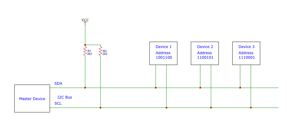
The Master and Slave Devices on the I2C Bus
The devices connected to the I2C bus are categorized as either masters or slaves. At any instant of time, only a single master stays active on the I2C bus. It controls the SCL clock line and decides what operation is to be done on the SDA data line.
All the devices that respond to instructions from this master device are slaves. For differentiating between multiple slave devices connected to the same I2C bus, each slave device is physically assigned a permanent 7-bit address.
When a master device wants to transfer data to or from a slave device, it specifies this particular slave device address on the SDA line and then proceeds with the transfer. So effectively communication takes place between the master device and a particular slave device.
All the other slave devices don’t respond unless their address is specified by the master device on the SDA line.
The Data Transfer Protocol
The protocol (set of rules) that is followed by the master device and slave devices for the transfer of data between them works as follows:
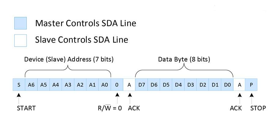
Data is transferred between the master device and slave devices through the SDA data line, via patterned sequences of 0’s and 1’s (bits). Each sequence of 0’s and 1’s is called a transaction and each data transaction is structured as in the image below:
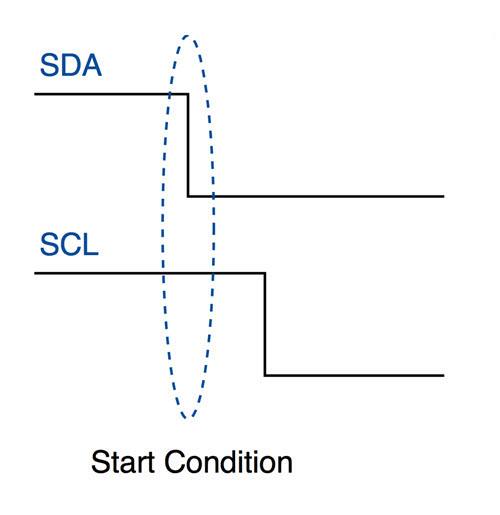
The Start Condition
Whenever a master device/IC decides to start a transaction, it switches the SDA line from a high level to a low level before the SCL line switches from high to low.
Once a start condition is sent by the master device, all the slave devices get active even if they were in sleep mode, and wait for the address bits to see which device should respond.
The Address Block
The Address block is comprised of 7 bits and are filled with the address of slave device (in binary) to/from which the master device needs to send/receive data. All the slave devices on the I2C bus will compare these address bits with their own address.
The Read/Write Bit
This bit specifies the direction that the data must be transferred in. If the master device/IC needs to send data to a slave device, this bit is set to ‘0’. If the master device/IC needs to receive data from the slave device, it is set to ‘1’.
The ACK/NACK Bit
This is the Acknowledged/Not-Acknowledged bit. If the physical address of any slave device is the same as the address that was broadcasted by the master device, that slave device will set the value of this bit to ‘0’ . If there are no slave device(s) with the broadcasted address, this bit will remain at logic ‘1’ (default). This will tell the master that the data/command has been received and/or acknowledged by a slave device.
The Data Block
The data block is comprised of 8 bits and they are set by the transmitter,wheather this be the master or the slave, depending on wheather a read or a write operation was requested, with the data bits that needs to transfered to the receiver. This block is followed by an ACK/NACK bit that is set to ‘0’ by the receiver if it successfully receives data. Otherwise it stays at logic ‘1’.
This combination of data blocks followed by an ACK/NACK bit is repeated until all the data is completely transferred.
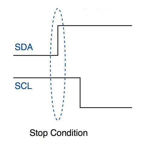
The Stop Condition
After all the required data blocks are transferred through the SDA line, the master device switches the SDA line from low to high before the SCL line switches back from high to low.
How does I2C work in practice
When an I2C transaction is initiated by a master device either to send or receive data to/from a slave device, all of the processes mentioned above will happen at least one.
Let us look at a typical scenario for each of the different type of scenarios.
Sending Data to a Slave Device
The following sequence of operations will take place when a master device tries to send data to a particular slave device through I2C bus:
- The master device sends a start condition
- The master device sends the 7 address bits which correspond to the slave device to be targeted
- The master device sets the Read/Write bit to ‘0’, which signifies a write
- Now two scenarios are possible:
- If no slave device matches with the address sent by the master device, the next ACK/NACK bit stays at ‘1’ (default). This signals the master device that the slave device identification is unsuccessful. The master clock will end the current transaction by sending a Stop condition or a new Start condition
- If a slave device exists with the same address as the one specified by the master device, the slave device sets the ACK/NACK bit to ‘0’, which signals the master device that a slave device is successfully targeted
- If a slave device is successfully targeted, the master device now sends 8 bits of data which is only considered and received by the targeted slave device. This data means nothing to the remaining slave devices
- If the data is successfully received by the slave device, it sets the ACK/NACK bit to ‘0’, which signals the master device to continue
- The previous two steps are repeated until all the data is transferred
- After all the data is sent to the slave device, the master device sends the Stop condition which signals all the slave devices that the current transaction has ended
The image below represents the transaction with the data bits sent on the SDA line and the device that controls each of them:
Reading Data from a Slave Device
The sequence of operations remain the same as in previous scenario except for the following:
- The master device sets the Read/Write bit to ‘1’ instead of ‘0’ which signals the targeted slave device that the master device is expecting data from it
- The 8 bits corresponding to the data block are sent by the slave device and the ACK/NACK bit is set by the master device
- Once the required data is received by the master device, it sends a NACK bit. Then the slave device stops sending data and releases the SDA line
If the master device to read data from specific internal location of a slave device, it first sends the location data to the slave device using the steps in previous scenario. It then starts the process of reading data with a repeated start condition.
The below figure represents the overall data bits sent on the SDA line and the device that controls each of them:
The Clock Stretching concept
Let say the master device started a transaction and sent address bits of a particular slave device followed by a Read bit of ‘1’. The specific slave device needs to send an ACK bit, immediately followed by data.
But if the slave device needs some time to fetch and send data to master device, during this gap, the master device will think that the slave device is sending some data.
To prevent this, the slave device holds the SCL clock line low until it is ready to transfer data bits. By doing this, the slave device signals the master device to wait for data bits until the clock line is released
Conclusion
This concludes this tutorial. In a future post, I will show you how to use I2C to transfer data between two micro-controllers.