I2C between Maker Nano and Kid-Bright32 (Esp32)

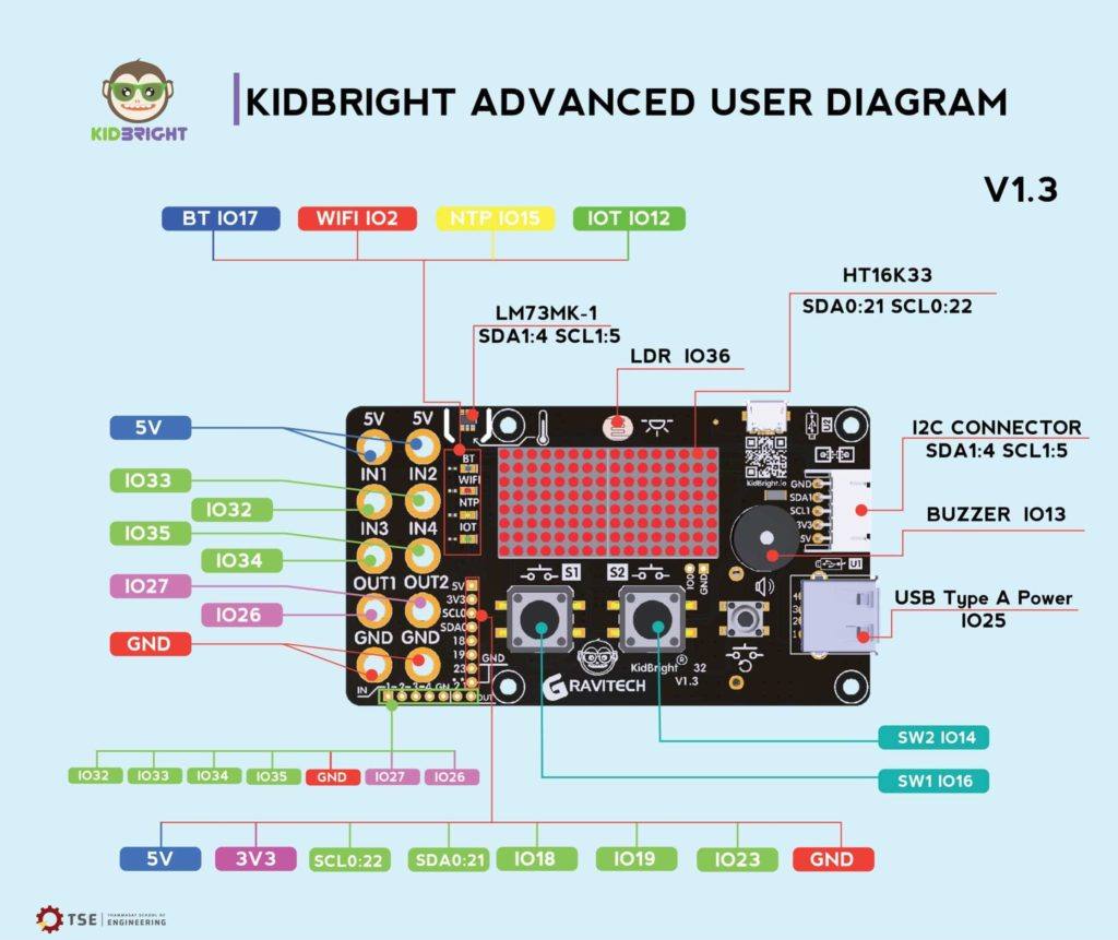
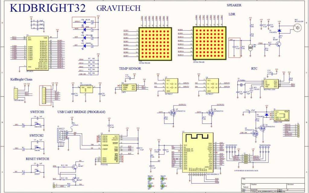
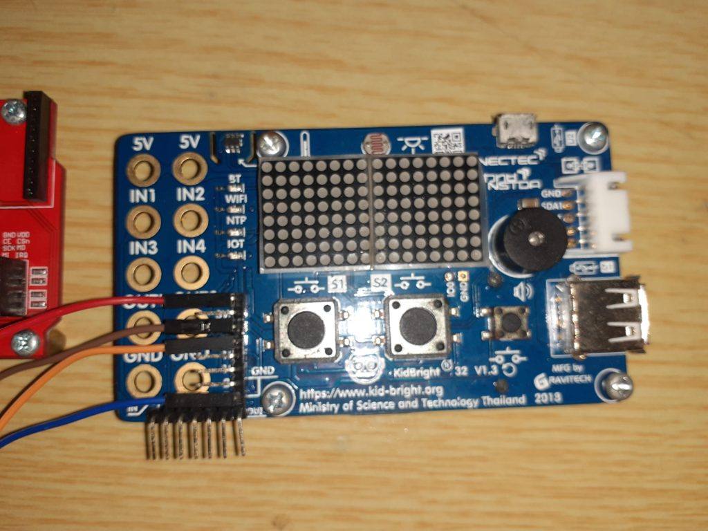
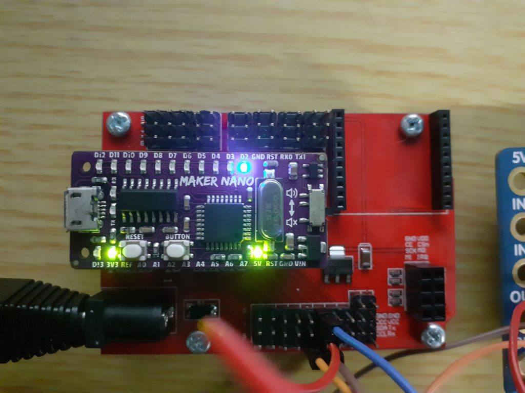
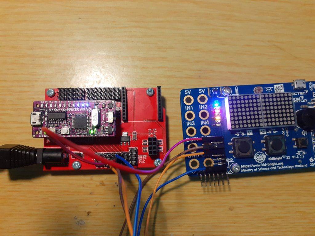
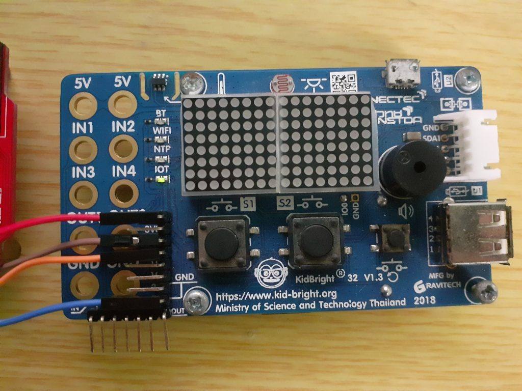
In our last post, we started looking at the workings of the I2C protocol. In case you missed that, you can read about that here. Today, I will continue with I2C by showing you how to implement the protocol between an Maker Nano (a Arduino Nano Clone) and Kid-Bright32 (a ESP32 based development and Education device).

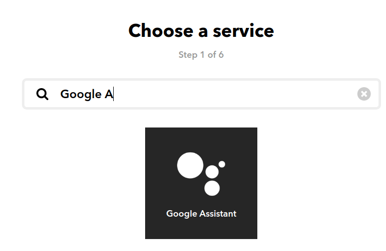
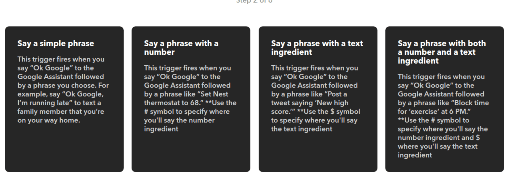
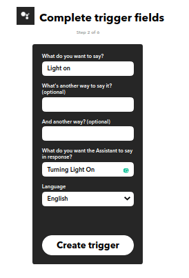
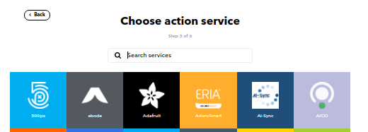
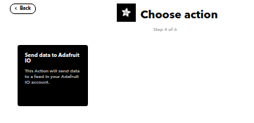
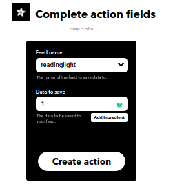
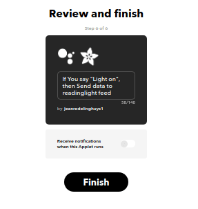
This project will eventually be turned into an IoT device, with Google Assistant voice control. The Kid-Bright have very limited IO pins, and the Maker Nano has no Network Connectivity unless we use an Ethernet Shield. Enough of that for now, let us start with today’s tutorial, we will get back to this project later…

The Code for the Master

/* I2C Master Code - Kid Bright 32 v 1.3
   Can be adapted to Arduino or NodeMCU or STM32
   As it uses no special libraries, only the standard Wire.h
   that is already included with the Arduino IDE
*/

#include <Wire.h>

#define button1 16 // Button 1
#define button2 14 // Button 2
#define led_blue 17 // Led 1
#define led_red 2 // Led 2
#define led_yellow 15 // Led 3


void setup() {
  Wire.begin(); // Start I2C, join bus as a Master
  pinMode(button1,INPUT_PULLUP); // Set as input
  pinMode(button2,INPUT_PULLUP); 
  pinMode(led_blue,OUTPUT); // Set as output
  pinMode(led_red,OUTPUT);
  pinMode(led_yellow,OUTPUT);
  digitalWrite(led_blue,HIGH); // LED is Active Low
  digitalWrite(led_red,HIGH); // LED is Active Low
  digitalWrite(led_yellow,HIGH); // LED is Active Low
  Serial.begin(115200); // Start Serial for debugging
}

byte Data = 0; // Variable for sending data to the slave
int SlaveData = 0; // Variable for receiving data from the slave

void loop() {
  Wire.beginTransmission(4); // Send data to Slave at address #4
  Wire.write(Data); // Transmit one byte ( 8 bits)
  Wire.endTransmission(); // End Transmission
  Wire.requestFrom(4,1); // Request one (1) byte of data from the      //slave at address$
  while (Wire.available()) { // If data received
    SlaveData = Wire.read(); // Save it into a variable
  }

// We will implement a simple latch in software, where a single 
// button latches or releases a bit with every press and release.  
// This code should ideally include debouncing as well. It was left
// out for clarity.

  if (digitalRead(button1) == LOW) { // If button 1 pressed
    if (bitRead(Data,0) == HIGH) { // test if bit 0 in variable is set
      bitClear(Data,0); // clear it if it is set
    } else {
      bitSet(Data,0) == HIGH; // set bit to high
    }
  } 
// Do the same for the second button

  if (digitalRead(button2) == LOW) {
    if (bitRead(Data,1) == HIGH) {
      bitClear(Data,1);
    } else {
      bitSet(Data,1) == HIGH;
    }
  } 
 
// We will test for a set bit in the transmitted byte, and invert it, 
// as the LED's are active LOW

  digitalWrite(led_blue,!bitRead(Data,0)); // Toggle Led 1
  digitalWrite(led_red,!bitRead(Data,1)); // Toggle Led 2

// Same with the data received from the slave

  digitalWrite(led_yellow,!bitRead(SlaveData,0)); // Toggle Led 3
  
// Print Debug info on serial port
  
  Serial.print("Send to Slave 0xb");
  Serial.println(Data,BIN);
  Serial.print("Received from Slave 0xb");
  Serial.println(SlaveData,BIN);
  
 // Small delay, should change to millis in production code

  delay(200);
       
}
The Master Device. Connections are +5v (red) SCL (brown) SDA (orange) Ground (blue)

Code for the Slave

/*
     I2C Slave
     Arduino Nano or Compatible, can be used with ESP32 or STM32
     as well as no special libraries used, only standard Wire.h
*/

#include <Wire.h>

#define button 2 // A user button
#define led1 3 // Led 1
#define led2 4 // Led 2

byte Data = 0; // Variable for sending data to the Master

void setup() 
{
  pinMode(button,INPUT_PULLUP); // Set as Input
  pinMode(led1,OUTPUT);
  pinMode(led2,OUTPUT);
  digitalWrite(led1,LOW); // Led is Active High, so switch it off
  digitalWrite(led2,LOW);
  Wire.begin(4); // Join I2C Bus as device #4
  Wire.onReceive(receiveEvent); // Register receive Event
  Wire.onRequest(requestEvent); // Register request event
  Serial.begin(115200); // start serial debugging
  
}

void loop() {
// implement a software bit latch, on bit 0 of the Data variable
// the latch is toggled by pressing and releasing the button
// should ideally be debounced as well

 if (digitalRead(button) == LOW) {
  if (bitRead(Data,0) == HIGH) {
    bitClear(Data,0);
  } else {
    bitSet(Data,0) == HIGH;
  }
 }
 delay(200); // small delay
}

// This event will be triggered when the master requests data

void requestEvent() 
{
  Wire.write(Data); // Send data to the master
  Serial.print("Sending to Master 0xb");
  Serial.println(Data,BIN);
}
// This event gets triggered when the master sends data

void receiveEvent(int Quantity)
{
  int x = Wire.read(); // read the data ( one byte in this case)
  digitalWrite(led1,bitRead(x,0)); // Toggle LED 1 on Bit 0 state
  digitalWrite(led2,bitRead(x,1)); // Toggle LED 2 on Bit 1 state
  Serial.print("Received from Master 0xb"); // Debugginh
  Serial.println(x,BIN);

}
Maker Nano on an IO Shield, Connections are +5v (red) SCL (brown) SDA (orange) Ground (blue)

How does this work.

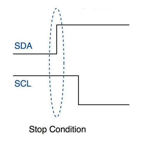
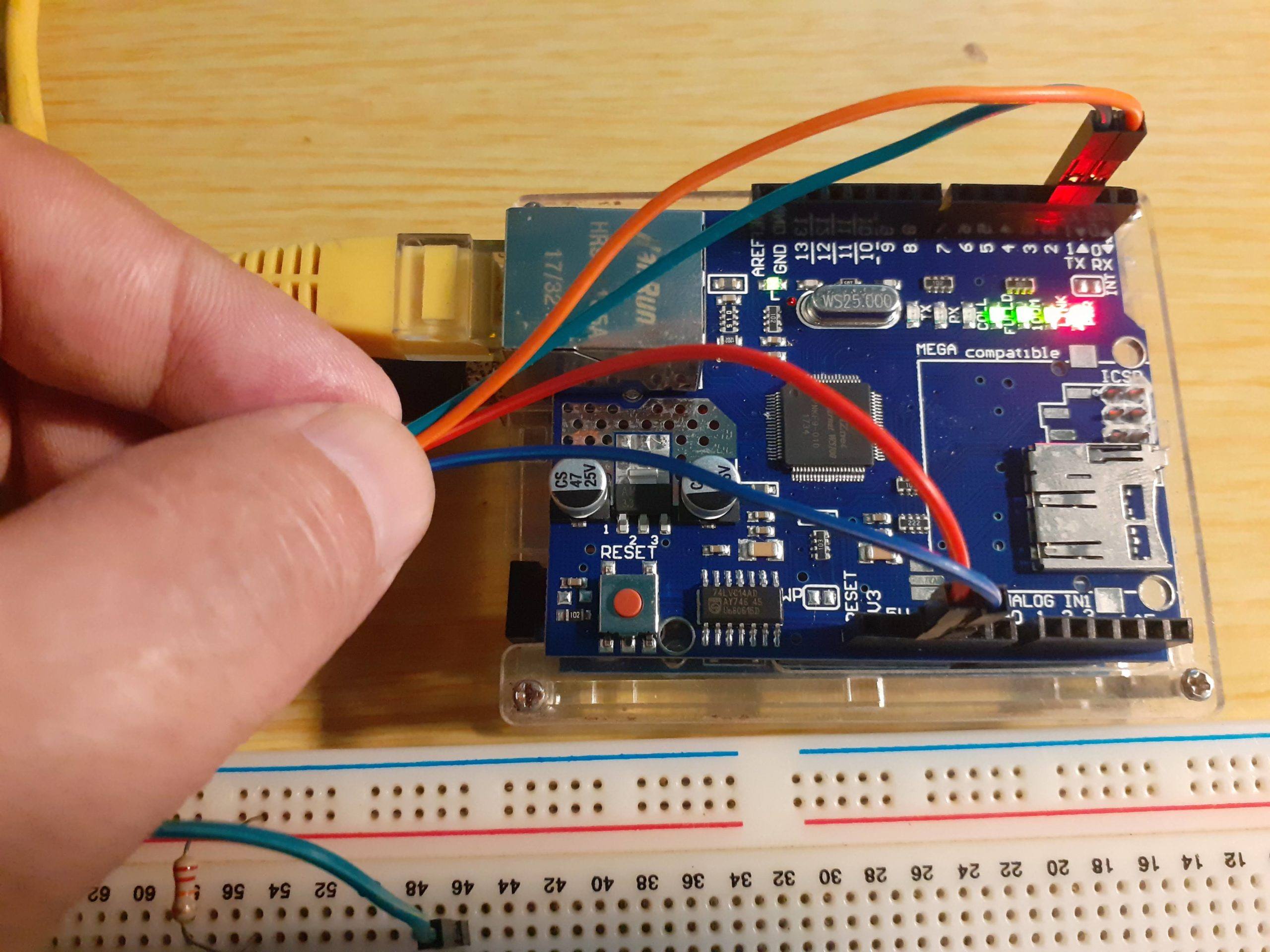
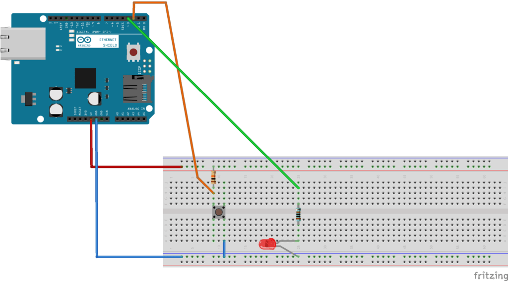
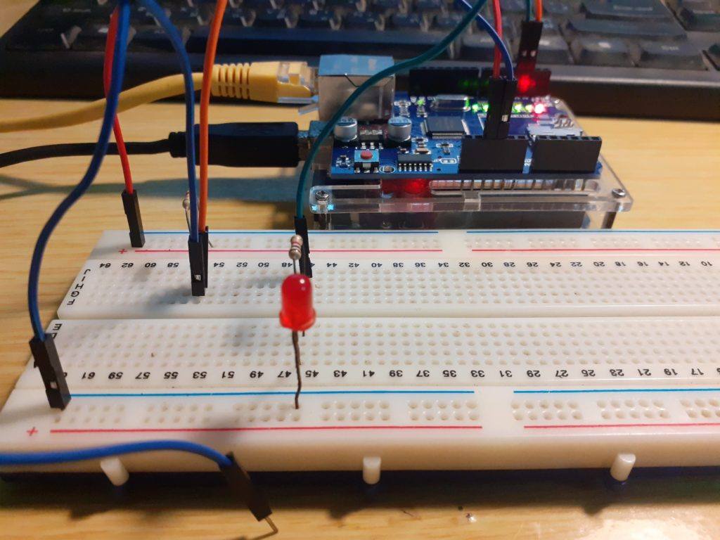
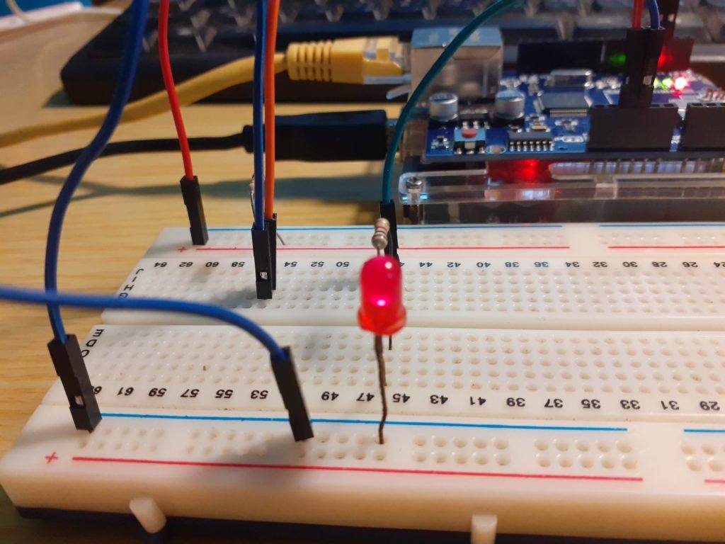
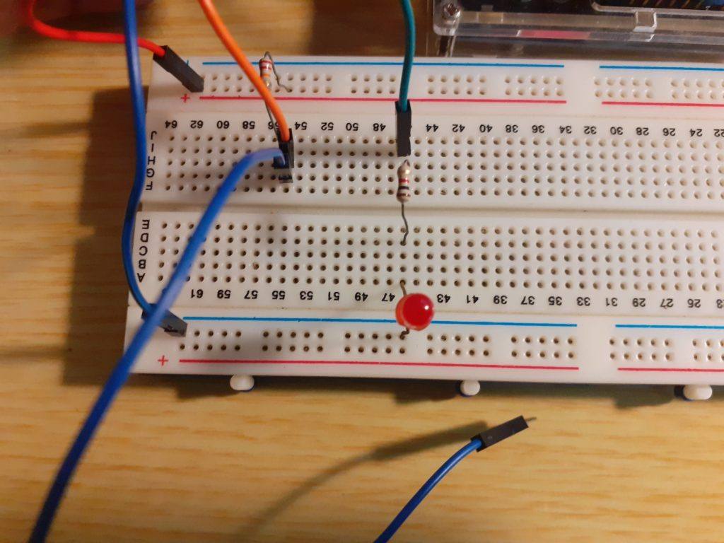
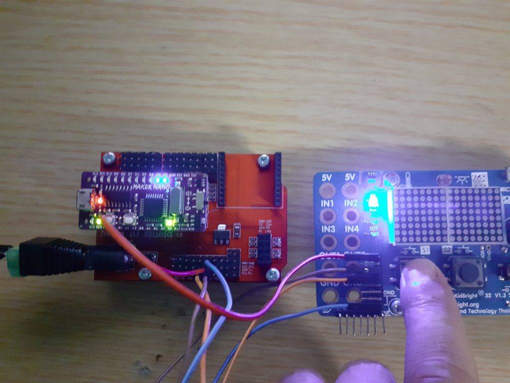
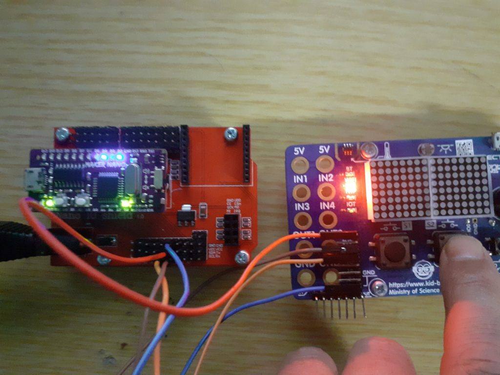
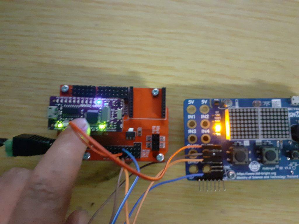
After uploading the code to the two boards, and connecting the boards to the I2C bus, we may power everything up. Please note that the boards MUST have a common ground. I have also powered both from the same supply. also make sure the SDA goes to SDA, and SCL to SCL… On a short distance like this, pull-up resistors are not required ( your milage may vary )

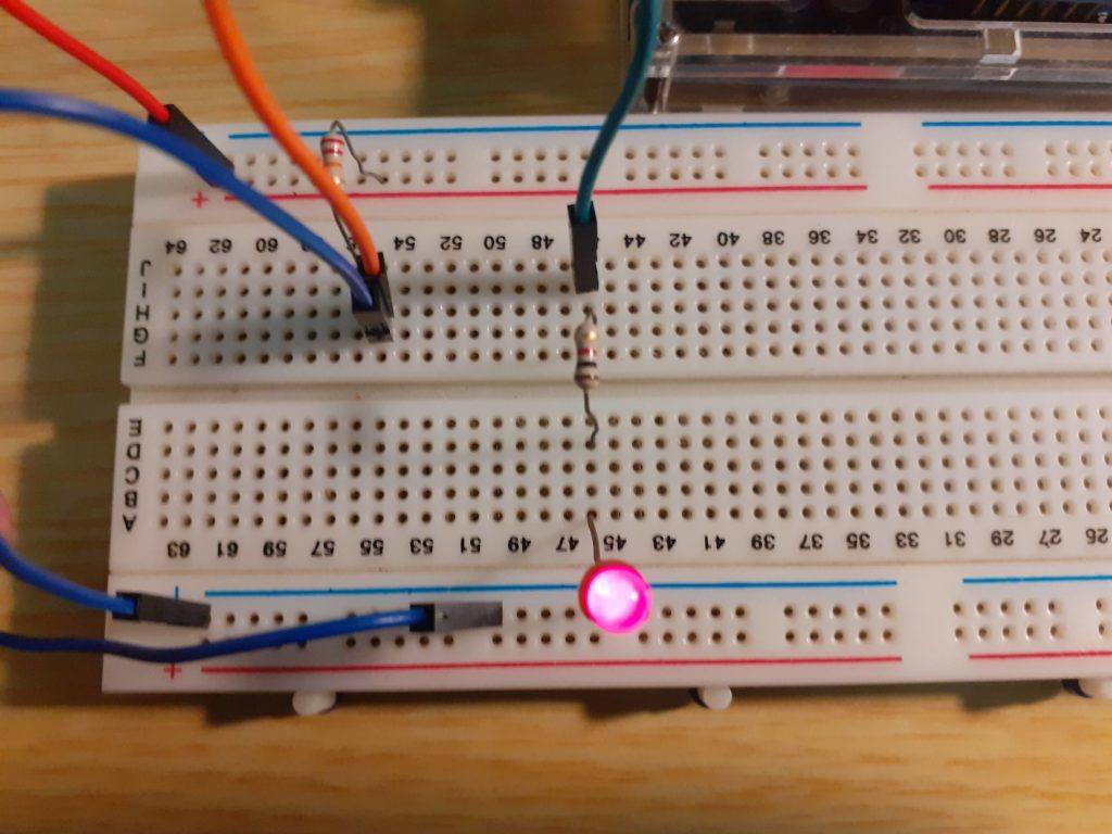
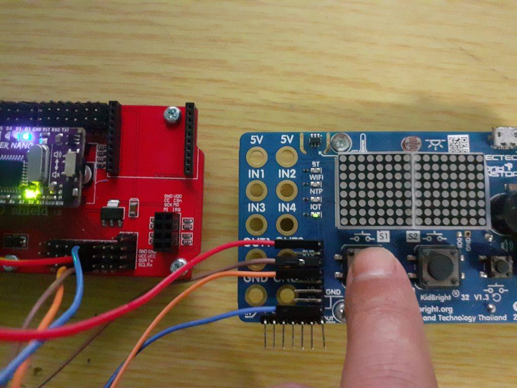
When we first power it up, is will seem as if nothing happened, but if you press and release one of the switches, the LED’s will light up, and stay lit until you press the switch again.
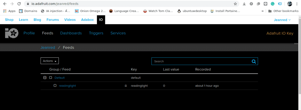
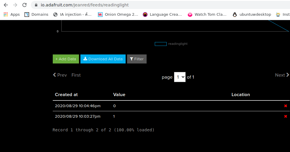
What next ?

In further parts of this, we will expand on this device, turning it into an IoT device, by combining many different skills that I have presented in previous tutorials.

What exactly is I2C?

In this post, I will tell you all the basics of the I2C protocol. What it is, where it comes from and also how it is configured and setup. We will also look at how data is transferred and received

Table of contents
1. Introduction
2. The Features of I2C
3. The Hardware
3.1 The physical I2C Bus
3.2 The Master and Slave devices on the bus
4. The data transfer protocol
4.1 The Start Condition
4.2 The Address Block
4.3 The Read/Write Bit
4.4 The ACK/NACK Bit
4.5 The Data Block
4.6 The Stop Condition
5. How does I2C work in practice
5.1 Sending data to a Slave Device
5.2 Reading data from a Slave Device
5.3 The Clock stretching concept

Introduction

I2C communication is the short form name for inter-integrated circuit protocol. It is a communication protocol developed by Philips Semiconductors for the transfer of data between a central processor and multiple integrated circuits on the same circuit board by using just two common wires.

Due to its simplicity, it is widely adopted for communication between microcontrollers and sensor arrays, displays, IoT devices, EEPROMs etc.

This is a synchronous serial communication protocol. It means that data bits are transferred one by one at regular intervals of time set by a reference clock line.

The Features of I2C

The I2C protocol has the following important features

  • Only two common bus lines (wires) are required to control any device/IC on the I2C network.
  • There is no need for a prior agreement on data transfer rate like in UART communications. The data transfer speed can thus be adjusted whenever it is required.
  • It has a simple mechanism for validating the transferred data.
  • It uses a 7-bit addressing system to target a specific device/IC on the I2C bus.
  • I2C networks are extremely easy to scale. New devices can simply be connected to the two common I2C bus lines.

The Hardware

The physical I2C Bus

The I2C Bus (Interface wires) consists of just two wires and are named Serial Clock Line (SCL) and Serial Data Line (SDA). The data to be transferred is sent through the SDA wire and is synchronized with the clock signal from SCL. All the devices/ICs on the I2C network are connected to the same SCL and SDA lines as shown in the image below:

The physical I2C Bus. All devices are connected to the same 2 wired on the bus, namely SDA and SCL

Both the I2C bus lines (SDA, SCL) are operated as in open-drain driver mode. It means that any device/IC on the I2C network can drive(pull) SDA and SCL low, but they cannot drive them high. So, a pull-up resistor is used on each bus line, to keep them high (at positive voltage) by default.

This is to prevent the bus from shorting, which might happen when one device tries to pull the line high and some other device tries to pull the line low.

The Master and Slave Devices on the I2C Bus

The devices connected to the I2C bus are categorized as either masters or slaves. At any instant of time, only a single master stays active on the I2C bus. It controls the SCL clock line and decides what operation is to be done on the SDA data line.

All the devices that respond to instructions from this master device are slaves. For differentiating between multiple slave devices connected to the same I2C bus, each slave device is physically assigned a permanent 7-bit address.

When a master device wants to transfer data to or from a slave device, it specifies this particular slave device address on the SDA line and then proceeds with the transfer. So effectively communication takes place between the master device and a particular slave device.

All the other slave devices don’t respond unless their address is specified by the master device on the SDA line.

The Master and Slave Devices on the I2C Bus. Note that each Slave device has it’s own address.

The Data Transfer Protocol

The protocol (set of rules) that is followed by the master device and slave devices for the transfer of data between them works as follows:

Data is transferred between the master device and slave devices through the SDA data line, via patterned sequences of 0’s and 1’s (bits). Each sequence of 0’s and 1’s is called a transaction and each data transaction is structured as in the image below:

The structure of an I2C Data transaction

The Start Condition

Whenever a master device/IC decides to start a transaction, it switches the SDA line from a high level to a low level before the SCL line switches from high to low.

Once a start condition is sent by the master device, all the slave devices get active even if they were in sleep mode, and wait for the address bits to see which device should respond.

The I2C Start Condition. Note that SDA Switches LOW before SCL. All slave devices on the bus will now listen for an address bit to decide which device should respond.

The Address Block

The Address block is comprised of 7 bits and are filled with the address of slave device (in binary) to/from which the master device needs to send/receive data. All the slave devices on the I2C bus will compare these address bits with their own address.

The Read/Write Bit

This bit specifies the direction that the data must be transferred in. If the master device/IC needs to send data to a slave device, this bit is set to ‘0’. If the master device/IC needs to receive data from the slave device, it is set to ‘1’.

The ACK/NACK Bit

This is the Acknowledged/Not-Acknowledged bit. If the physical address of any slave device is the same as the address that was broadcasted by the master device, that slave device will set the value of this bit to ‘0’ . If there are no slave device(s) with the broadcasted address, this bit will remain at logic ‘1’ (default). This will tell the master that the data/command has been received and/or acknowledged by a slave device.

The Data Block

The data block is comprised of 8 bits and they are set by the transmitter,wheather this be the master or the slave, depending on wheather a read or a write operation was requested, with the data bits that needs to transfered to the receiver. This block is followed by an ACK/NACK bit that is set to ‘0’ by the receiver if it successfully receives data. Otherwise it stays at logic ‘1’.

This combination of data blocks followed by an ACK/NACK bit is repeated until all the data is completely transferred.

The Stop Condition

After all the required data blocks are transferred through the SDA line, the master device switches the SDA line from low to high before the SCL line switches back from high to low.

The I2C Stop condition. This signals the end of a transaction. Note SDA returns to High BEFORE the SCL line is pulled High.

How does I2C work in practice

When an I2C transaction is initiated by a master device either to send or receive data to/from a slave device, all of the processes mentioned above will happen at least one.
Let us look at a typical scenario for each of the different type of scenarios.

Sending Data to a Slave Device

The following sequence of operations will take place when a master device tries to send data to a particular slave device through I2C bus:

  • The master device sends a start condition
  • The master device sends the 7 address bits which correspond to the slave device to be targeted
  • The master device sets the Read/Write bit to ‘0’, which signifies a write
  • Now two scenarios are possible:
    • If no slave device matches with the address sent by the master device, the next ACK/NACK bit stays at ‘1’ (default). This signals the master device that the slave device identification is unsuccessful. The master clock will end the current transaction by sending a Stop condition or a new Start condition
    • If a slave device exists with the same address as the one specified by the master device, the slave device sets the ACK/NACK bit to ‘0’, which signals the master device that a slave device is successfully targeted
  • If a slave device is successfully targeted, the master device now sends 8 bits of data which is only considered and received by the targeted slave device. This data means nothing to the remaining slave devices
  • If the data is successfully received by the slave device, it sets the ACK/NACK bit to ‘0’, which signals the master device to continue
  • The previous two steps are repeated until all the data is transferred
  • After all the data is sent to the slave device, the master device sends the Stop condition which signals all the slave devices that the current transaction has ended

The image below represents the transaction with the data bits sent on the SDA line and the device that controls each of them:

I2C Master sending data to a slave device

Reading Data from a Slave Device

The sequence of operations remain the same as in previous scenario except for the following:

  • The master device sets the Read/Write bit to ‘1’ instead of ‘0’ which signals the targeted slave device that the master device is expecting data from it
  • The 8 bits corresponding to the data block are sent by the slave device and the ACK/NACK bit is set by the master device
  • Once the required data is received by the master device, it sends a NACK bit. Then the slave device stops sending data and releases the SDA line

If the master device to read data from specific internal location of a slave device, it first sends the location data to the slave device using the steps in previous scenario. It then starts the process of reading data with a repeated start condition.

The below figure represents the overall data bits sent on the SDA line and the device that controls each of them:

Reading data from a Slave device on the I2C bus

The Clock Stretching concept

Let say the master device started a transaction and sent address bits of a particular slave device followed by a Read bit of ‘1’. The specific slave device needs to send an ACK bit, immediately followed by data.

But if the slave device needs some time to fetch and send data to master device, during this gap, the master device will think that the slave device is sending some data.

To prevent this, the slave device holds the SCL clock line low until it is ready to transfer data bits. By doing this, the slave device signals the master device to wait for data bits until the clock line is released

Conclusion

This concludes this tutorial. In a future post, I will show you how to use I2C to transfer data between two micro-controllers.


Arduino Web Server – Part 2

Introduction


In my previous post, I showed you how to use AJAX and JavaScript to make a very responsive Web server on Arduino. In Part 2, we will look at making some important modifications.

Arduino has limited storage space – Use an SD Card

As all of us already know, the Arduino, especially the Uno and Nano, has very limited storage space. If we want to create a truly useful IoT Web server device, we need to do something to increase the available storage space on our Arduino Device.

We can however not increase the program memory. What we can do is store our static HTML page, as well as any images and icons, on a SD-CARD. These come in many sizes,
but for our example, I will use a 2gb card, not that we will use all of it anyway.

The standard Arduino Ethernet Shield also comes standard with a SD-CARD reader slot already built in.

Arduino Ethernet Shield for Arduino Uno or Mega. Note That SD Card Slot is already built in

This makes our lives a lot easier. You can also buy a stand-alone SPI SD Card module for a few bucks online. This will be needed if you try to make this project using an Arduino Nano.

Preparing the Card for use

You should format your card using your computer, and a suitable adapter. The card should be formatted to the FAT filesystem. NTFS or other filesystems does unfortunately not work as far as I know.

SD Card IO – How to use the SD Card in Arduino

The Arduino IDE already includes an SD Card library. You can also download additional libraries from the internet that allows more specialized control and functionality. The standard library will however be sufficient for our needs.

It is also easy to test if your card is working or not. The code below is from the “CardInfo” example that ships with the Arduino IDE

/*
  SD card test

  This example shows how use the utility libraries on which the'
  SD library is based in order to get info about your SD card.
  Very useful for testing a card when you're not sure whether its working or not.

  The circuit:
    SD card attached to SPI bus as follows:
 ** MOSI - pin 11 on Arduino Uno/Duemilanove/Diecimila
 ** MISO - pin 12 on Arduino Uno/Duemilanove/Diecimila
 ** CLK - pin 13 on Arduino Uno/Duemilanove/Diecimila
 ** CS - depends on your SD card shield or module.
 		Pin 4 used here for consistency with other Arduino examples


  created  28 Mar 2011
  by Limor Fried
  modified 9 Apr 2012
  by Tom Igoe
*/
// include the SD library:
#include <SPI.h>
#include <SD.h>

// set up variables using the SD utility library functions:
Sd2Card card;
SdVolume volume;
SdFile root;

// change this to match your SD shield or module;
// Arduino Ethernet shield: pin 4
// Adafruit SD shields and modules: pin 10
// Sparkfun SD shield: pin 8
// MKRZero SD: SDCARD_SS_PIN
const int chipSelect = 4;

void setup() {
  // Open serial communications and wait for port to open:
  Serial.begin(9600);
  while (!Serial) {
    ; // wait for serial port to connect. Needed for native USB port only
  }


  Serial.print("\nInitializing SD card...");

  // we'll use the initialization code from the utility libraries
  // since we're just testing if the card is working!
  if (!card.init(SPI_HALF_SPEED, chipSelect)) {
    Serial.println("initialization failed. Things to check:");
    Serial.println("* is a card inserted?");
    Serial.println("* is your wiring correct?");
    Serial.println("* did you change the chipSelect pin to match your shield or module?");
    while (1);
  } else {
    Serial.println("Wiring is correct and a card is present.");
  }

  // print the type of card
  Serial.println();
  Serial.print("Card type:         ");
  switch (card.type()) {
    case SD_CARD_TYPE_SD1:
      Serial.println("SD1");
      break;
    case SD_CARD_TYPE_SD2:
      Serial.println("SD2");
      break;
    case SD_CARD_TYPE_SDHC:
      Serial.println("SDHC");
      break;
    default:
      Serial.println("Unknown");
  }

  // Now we will try to open the 'volume'/'partition' - it should be FAT16 or FAT32
  if (!volume.init(card)) {
    Serial.println("Could not find FAT16/FAT32 partition.\nMake sure you've formatted the card");
    while (1);
  }

  Serial.print("Clusters:          ");
  Serial.println(volume.clusterCount());
  Serial.print("Blocks x Cluster:  ");
  Serial.println(volume.blocksPerCluster());

  Serial.print("Total Blocks:      ");
  Serial.println(volume.blocksPerCluster() * volume.clusterCount());
  Serial.println();

  // print the type and size of the first FAT-type volume
  uint32_t volumesize;
  Serial.print("Volume type is:    FAT");
  Serial.println(volume.fatType(), DEC);

  volumesize = volume.blocksPerCluster();    // clusters are collections of blocks
  volumesize *= volume.clusterCount();       // we'll have a lot of clusters
  volumesize /= 2;                           // SD card blocks are always 512 bytes (2 blocks are 1KB)
  Serial.print("Volume size (Kb):  ");
  Serial.println(volumesize);
  Serial.print("Volume size (Mb):  ");
  volumesize /= 1024;
  Serial.println(volumesize);
  Serial.print("Volume size (Gb):  ");
  Serial.println((float)volumesize / 1024.0);

  Serial.println("\nFiles found on the card (name, date and size in bytes): ");
  root.openRoot(volume);

  // list all files in the card with date and size
  root.ls(LS_R | LS_DATE | LS_SIZE);
}

void loop(void) {
}

Open this example in your Arduino IDE, and then make sure that the CS pin is set to the correct pin for your Ethernet Shield ( Pin 10 is for Ethernet, Pin 4 is usually for the SD Card).

Both of these devices will be connected to the SPI bus on your Arduino, and the CS pin will determine which device is active, by being pulled LOW.

Insert your formatted card into the slot, power on the Arduino, and upload the sketch to the Arduino. Open the Serial monitor. If all goes well, you should see information about your SD Card ( Size, sectors etc being displayed ). If your card was already formatted to the FAT file system and contained other files, the names of these files will also be displayed.

Create your Web Page

Power down the Arduino, and remove the SD Card. Put it into the relevant adapter and connect it to your computer.

Now, open a plain text editor, notepad on windows, or any other specialized html editor, as long as you feel comfortable with it, and create a simple html file. Feel free to use my example below, and modify it to your liking

<!DOCTYPE html>
<html>
    <head>
        <title>Arduino SD Card Web Page EXAMPLE - Maker and IOT Ideas</title>
    </head>
    <body>
        <h1>Welcome to your Arduino Based Web Server</h1>
        <p>This page is stored on the SD Card connected to your Arduino.</p>
        <p>Please do not remove the card while the Arduino is connected to a power source</p>

    </body>
</html>

Save this file as index.htm, and remove the card from your computer, making sure that you properly stop it as per the standard procedures for your operating system.

Put it back into the slot on the Arduino Ethernet Shield, open the serial monitor, and apply power to your Arduino. make sure that you see the file, index.htm listed in the output.

Coding your Webserver

Our next step will be to write the code to create our Arduino Web Server. This code will be similar to the code in part 1 of this series, but I recommend that you start fresh, open a new sketch, and copy-paste my code into the IDE. you can always modify it later to suit your needs…

#include <SPI.h>
#include <Ethernet.h>
#include <SD.h>

// MAC address from Ethernet shield sticker under board
byte mac[] = { 0xDE, 0xAD, 0xBE, 0xEF, 0xFE, 0xED };
IPAddress ip(192, 168, 100, 32); // IP address, may need to change depending on network
EthernetServer server(80);  // create a server at port 80

File webFile;

void setup()
{
    
    
    // initialize SD card
    Serial.println("Initializing SD card...");
    if (!SD.begin(4)) {
        Serial.println("ERROR - SD card initialization failed!");
        return;    // init failed
    }
    Serial.println("SD card initialized. [OK]");
    // check for index.htm file
    if (!SD.exists("index.htm")) {
        Serial.println("ERROR - Can't find index.htm file!");
        return;  // can't find index file
    }
    Serial.println("index.htm file found - Starting Webserver");

    Ethernet.begin(mac, ip);  // initialize Ethernet device
    server.begin();           // start to listen for clients
    Serial.begin(9600);       // for debugging
}

void loop()
{
    EthernetClient client = server.available();  // try to get client

    if (client) {  // got client?
        boolean currentLineIsBlank = true;
        while (client.connected()) {
            if (client.available()) {   // client data available to read
                char c = client.read(); // read 1 byte (character) from client
                // last line of client request is blank and ends with \n
                // respond to client only after last line received
                if (c == '\n' && currentLineIsBlank) {
                    // send a standard http response header
                    client.println("HTTP/1.1 200 OK");
                    client.println("Content-Type: text/html");
                    client.println("Connection: close");
                    client.println();
                    // send web page
                    webFile = SD.open("index.htm");        // open web page file
                    if (webFile) {
                        while(webFile.available()) {
                            client.write(webFile.read()); // send web page to client
                        }
                        webFile.close();
                    }
                    break;
                }
                // every line of text received from the client ends with \r\n
                if (c == '\n') {
                    // last character on line of received text
                    // starting new line with next character read
                    currentLineIsBlank = true;
                } 
                else if (c != '\r') {
                    // a text character was received from client
                    currentLineIsBlank = false;
                }
            } // end if (client.available())
        } // end while (client.connected())
        delay(1);      // give the web browser time to receive the data
        client.stop(); // close the connection
    } // end if (client)
}

Upload the sketch to your Arduino and navigate to the IP Address of the server using your browser. You should see the page displayed as you coded it.

What to do from here

You can now modify your page to include links and even images and CSS styling. You should however remember that the Arduino also does not have a lot of RAM memory.
You should thus not add extremely large images or pages. Those will take a long time to display, or may even time-out and not display at all

In the next part of this series, I will show you how to add links, images and CSS to make your page look a bit more visually appealing. We will also integrate the AJAX and JavaScript
functionality from the previous part of the series, to allow our server to interact with the inputs and outputs on the Arduino.

Arduino Web Server using AJAX – Part 1

There are many ways to use Arduino to create your own IoT device. One of the easiest is to configure your Arduino as a Web Server. This way, you can connect to it from any browser capable device on your home network. It is also quite a bit safer to do it this way, as you don’t have to expose your device to the internet, reducing the security implications of many of the other methods available.

It does, however, have the disadvantage of not being able to connect to your device from outside your home network. ( In a later part of this series, I will show you how to do this relatively safely, but take note that you still won’t have SSH encryption to the device, that is a huge security risk in today’s online world.

What use will this kind of IoT device have?

You can use an Arduino based web server to monitor various devices in your home, as well as control them. Many of us have old Android tablets and other devices lying around, that may be to old to run the newest Android Operating System. Such a Tablet can however be mounted to a wall, to provide a permanent display and control device. You will only be limited by your imagination, as well as your skill with interfacing your devices with electronics and Arduino.

A few examples of this can be
– controlling lights
– controlling a fan
– measuring temperature and light levels using various sensors, and performing actions based on those values

But Arduino Web Servers are slow

The normal Arduino web servers that we have all seen in various projects on the internet are indeed slow and cumbersome. This is because they usually have to refresh and reload the entire page to display every single update of a switch or output. We can however take advantage of technology used on computer web servers, as well as the browser of the end user.

Ajax and Javascript

What is AJAX?

AJAX stands for Asynchronous JavaScript and XML.

AJAX is basically the use of JavaScript functions for getting information from the webserver (Your Arduino). This means that data on a web page can be updated without fetching the whole page each time.

This means that only the relevant part of the web page will be updated, either automatically, or when the end user performs an action, like click on a button, or when an input on the actual Arduino changes state.

What is JavaScript?

JavaScript is a client-side scripting language. This means that the code will run on the web browser. Meaning on the end-user computer or mobile device.

The JavaScript is included in the HTML page that will be served by the Arduino Webserver. When you load the web page hosted by the Arduino, the page and the JavaScript is loaded to your browser. Your browser then runs the JavaScript code (provided that you have not disabled JavaScript in your browser).

What will we need to do this?

You will need the following hardware and software to do this project

– Arduino UNO or Compatible
– Arduino Ethernet Shield with NO SD-Card Inserted
– Breadboard
– 1K resistor
– LED
– 10k OR 22k Resistor
– Hookup Wire (5 pieces)
– Push Button

The Circuit

Wire the following circuit on your breadboard

Circuit Diagram for the Arduino AJAX Web Server – Part 1

Connect your Ethernet Shield to the Arduino Uno.
Connect the Resistors, LED and push-button Switch as shown.
Connect +5v from Arduino to Red Line, Gnd From Arduino to Blue line

Connect Orange Wire from Arduino Pin 2 to a hole BETWEEN the 10k resistor and the switch ( See Diagram).
Connect Green Wire from Arduino Pin 3 to a hole above the 1k resistor ( See Diagram)

The Code

Copy the following code into your Arduino IDE, Or download the file below

#include <SPI.h>
#include <Ethernet.h>
// MAC address from Ethernet shield sticker under board
byte mac[] = { 0xDE, 0xAD, 0xBE, 0xEF, 0xFE, 0xED };
IPAddress ip(192, 168, 100, 32); // IP address, may need to change depending on network
EthernetServer server(80); // create a server at port 80
String HTTP_req; // stores the HTTP request

void setup()
{
Ethernet.begin(mac, ip); // initialize Ethernet device
server.begin(); // start to listen for clients
Serial.begin(9600); // for diagnostics
pinMode(2, INPUT_PULLUP); // switch is attached to Arduino pin 2
pinMode(3, OUTPUT);
digitalWrite(3,LOW);
}

void loop()
{
EthernetClient client = server.available(); // try to get client
if (client) { // got client? 
boolean currentLineIsBlank = true; 
while (client.connected()) 
{ if (client.available()) 
{ // client data available to read char c = client.read(); // read 1 byte (character) from client HTTP_req += c; // save the HTTP request 1 char at a time 
// last line of client request is blank and ends with \n 
// respond to client only after last line received 
if (c == '\n' && currentLineIsBlank) { // send a standard http response header client.println("HTTP/1.1 200 OK"); 
client.println("Content-Type: text/html"); 
client.println("Connection: keep-alive"); 
client.println(); // AJAX request for switch state 
if (HTTP_req.indexOf("ajax_switch") > -1) 
{ 
// read switch state and send appropriate paragraph text 
GetSwitchState(client); 
} else 
{ 
// HTTP request for web page // send web page - contains JavaScript with AJAX calls 
client.println("<!DOCTYPE html>"); 
client.println("<html>"); 
client.println("<head>"); 
client.println("<title>Arduino Web Page with AJAX - Maker and IoT Ideas</title>"); 
client.println("<script>"); 
client.println("function GetSwitchState() {"); 
client.println("nocache = \"&nocache=\"\ + Math.random() * 1000000;"); 
client.println("var request = new XMLHttpRequest();"); 
client.println("request.onreadystatechange = function() {"); 
client.println("if (this.readyState == 4) {"); 
client.println("if (this.status == 200) {"); 
client.println("if (this.responseText != null) {"); client.println("document.getElementById(\"switch_txt\")\.innerHTML =this.responseText;");

client.println("}}}}");
client.println("request.open(\"GET\", \"ajax_switch\" + nocache, true);");
client.println("request.send(null);");
client.println("setTimeout('GetSwitchState()', 1000);");
client.println("}");
client.println("");
client.println("");
client.println(""); 
client.println("Arduino Web Server with AJAX"); 
client.println("Switch Status on D2"); 
client.println( "Switch state: Not requested…"); 
client.println("");
client.println("");
}
// display received HTTP request on serial port
Serial.print(HTTP_req);
HTTP_req = ""; // finished with request, empty string
break;
}
// every line of text received from the client ends with \r\n
if (c == '\n') {
// last character on line of received text
// starting new line with next character read
currentLineIsBlank = true;
}
else if (c != '\r') {
// a text character was received from client
currentLineIsBlank = false;
}
} // end if (client.available())
} // end while (client.connected())
delay(1); // give the web browser time to receive the data
client.stop(); // close the connection
} // end if (client)
}

// send the state of the switch to the web browser
void GetSwitchState(EthernetClient cl)
{
if (digitalRead(2)) {
cl.println("Switch at D2 is: OFF, LED at D3 is OFF");
digitalWrite(3,LOW);
}
else {
cl.println("Switch at D2 is: ON, LED at D2 is ON");
digitalWrite(3,HIGH);
}
}

Upload the code to your Arduino

Testing the results

Open a web browser and go to the IP Address of the server ( the one you set in your code).
If you did everything correctly, you should see a screen similar to this.

The Ajax Web Server shows the button and LED is OFF

Now press the button

The web page should immediately update and tell you that the button is On, and the LED is ON


Ajax Web Server showing Status of Button and LED as ON

The Generated HTML will look like this

<!DOCTYPE html>

<html>

<head>

<title>Arduino Web Page with AJAX - Maker and IoT Ideas</title>

<script>

function GetSwitchState() {

nocache = "&nocache=" + Math.random() * 1000000;

var request = new XMLHttpRequest();

request.onreadystatechange = function() {

if (this.readyState == 4) {

if (this.status == 200) {

if (this.responseText != null) {

document.getElementById("switch_txt").innerHTML = this.responseText;

}}}}

request.open("GET", "ajax_switch" + nocache, true);

request.send(null);

setTimeout('GetSwitchState()', 1000);

}

</script>

</head>

<body onload="GetSwitchState()">

<h1>Arduino Web Server with AJAX</h1>

<h3>Switch Status on D2</h3>

<p id="switch_txt">Switch state: Not requested...</p>

</body>

</html>

Images of the Working Hardware

Please note that I did not use a push button switch in my example. I have just used a piece of hookup wire to connect the pulled-up pin to ground, as it is easier to photograph that way, without my finger being in the way on a button. 🙂

Conclusion

This concludes part 1 of this series. This example can very easily be extended to be more useful, as well as be modified to work on other platforms, like ESP32.
In further parts, I will show you how to extend this very simple server into becoming something much more useful. Please visit again to see the rest of this series.

ESP32 (Kid Bright v 1.3) Voice-Activated IoT Relay Control using IFTTT and Adafruit IO

Today I will show you how to do a very quick IoT relay controller using IFTTT and Adafruit IO. I will be using the Kid Bright v 1.3 Development board, from Gravitec in Thailand. These boards sell for about $USD 25 to 35 each, quite expensive as far as I am concerned, for the amount of functionality that you get.

I will also post a link to the Video Tutorial at the bottom of this tutorial.

Kid Bright v 1,3 Development Board, Advanced user Diagram
Kid Bright 32 Schematic

You can find out more about this board on the Kid Bright Website. Please note that you will need Google Translate, as the site is in the Thai Language.

We will use IFTTT to connect Google Assistant to Adafruit IO in order to control our IoT Relay controller with voice commands.

Let us start our project.

Start the Arduino IDE, and make sure that you have enabled support for NodeMCU or other ESP32 based processors.
You also need to load the libraries for Adafruit IO.

After you have done that, open the “adafruitio_07_digital_out” sketch from the Examples folder for Adafruit IO. We will modify this example to suit our needs, as well as save some time on coding.

Change the Example to the following:
Remember to change the pins to reflect your particular setup.

include “config.h”

define LED_PIN 17
define Relay 27

// set up the ‘readinglight’ feed
AdafruitIO_Feed *readinglight = io.feed(“readinglight”);

void setup() {

pinMode(LED_PIN, OUTPUT);
pinMode(Relay, OUTPUT);

// start the serial connection
Serial.begin(115200);

// wait for serial monitor to open
while(! Serial);

// connect to io.adafruit.com
Serial.print(“Connecting to Adafruit IO”);
io.connect();

// set up a message handler for the ‘readinglight’ feed.
// the handleMessage function (defined below)
// will be called whenever a message is
// received from adafruit io.
readinglight->onMessage(handleMessage); // Handler for our FEED

// wait for a connection
while(io.status() < AIO_CONNECTED) {
Serial.print(“.”);
delay(500);
}

// we are connected
Serial.println();
Serial.println(io.statusText());
readinglight->get();

}

void loop() {

// io.run(); is required for all sketches.
// it should always be present at the top of your loop
// function. it keeps the client connected to
// io.adafruit.com, and processes any incoming data.
io.run();

}

// this function is called whenever an ‘readinglight’ feed message
// is received from Adafruit IO. it was attached to
// the ‘digital’ feed in the setup() function above.
void handleMessage(AdafruitIO_Data *data) {

Serial.print(“received <- “);

if(data->toPinLevel() == HIGH)
Serial.println(“HIGH”);
else
Serial.println(“LOW”);

digitalWrite(LED_PIN, !data->toPinLevel()); // We inverse the logic on the LED, we want it on //when the relay is on, and off when the relay is off
digitalWrite(Relay, data->toPinLevel()); // My Relay Module is Active LOW, so this is correct.
//reverse the logic if your module is Active High
}

Another very important step is that you need to set your Adafruit IO IO-Key in the config.h file. Your Wifi SSID and Password also needs to be supplied here, to enable your ESP32 based processor to connect to Adafruit through your WiFi connection.

Config.h

/ Adafruit IO Config */
define IO_USERNAME “your AdafruitIO username”
define IO_KEY “your AdafruitIO IO Key”
define WIFI_SSID “your wifi ssid”
define WIFI_PASS “your wifi password”

Leave everything else as is in the config.h file

Now login to Adafruit IO, or create a new account if you have not done so already.
Create a new feed, in my case called readinglight, under your feeds.

Click on the Adafruit IO Key button ( top right corner ) and copy your IO Key and Username into the config.h file in the Arduino IDE. Don’t upload your code yet.

Now go to IFTTT, and login or create a new account if you don’t have one already.
After you have logged in, in a new window, go to https://www.ifttt.com/adafruit

Make sure to connect Adafruit and IFTTT, and allow IFTTT to send messages to Adafruit IO.

Then, follow the pictures, and create your first applet.

Select “Say a Simple phrase”
Configure it with what you want to say to activate the relay, Then Click “Create Trigger”
Click on :Adafruit”
Click Send Data to Adafruit IO
Select you feed from the drop-down box. IMPORTANT, USE A 1 to switch something ON, or a 0 to switch it OFF. HIGH AND LOW, or ON and OFF DOES NOT WORK ! Then Click on Create Action
Review your applet, Switch OFF notifications, and Click on Finish.

Now create another Applet, Doing exactly the same, but change your wording to “Light OFF” and the Adafruit IO Data to 0. This applet will be used to switch off the Relay.

Go back to the Feed window in Adafruit IO, and then test Google Assistant by saying your command, like “Hey Google, Light On” and “Hey Google, Light Off”

You should see data arriving in your feed window after each command. A 1 for On and a 0 for Off.

Now go back to your Arduino IDE, Open the Serial Monitor, and Compile and Upload your Code. Test it again, but now you should see data arriving in the Serial Monitor as well.

If all of this is working, You can connect your Relay to the board, and test it again.
When you are happy that all is working as it should, Connect a load to the relay, and enjoy your new Voice-Activated IoT Relay Controller.

It is also easy to add another feed to the existing code. Ask me how if you don’t understand, but it should be quite easy to figure out from the code as well 🙂

https://youtu.be/Q-uwU55VAF4
Voice Controlled IoT Relay controller using Google Assistant, IFTTT and Adafruit IO