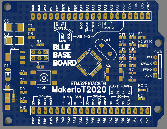
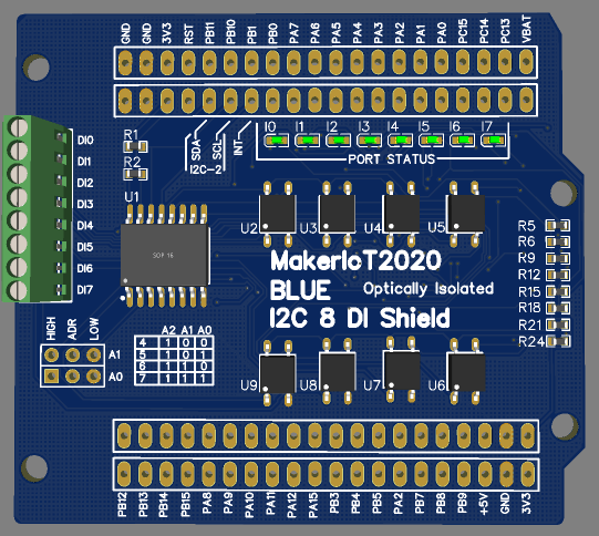
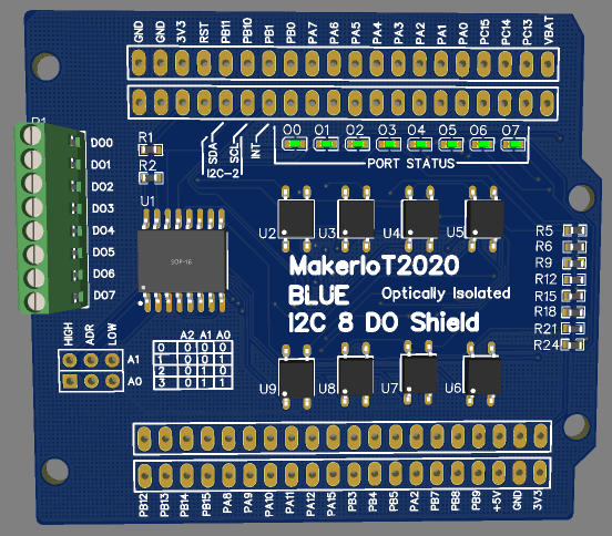
Everyone likes some free stuff once in a while. I have decided to release 3 recent PCB projects for free, no strings attached. The PCB’s include a STM32F103C8T6 ( BluePill ) in Arduino Uno Form Factor, as well as an additional two I2C IO Extender Shields, 8 DI and 8 DO, Both optically isolated, in a stack-able, addressable format.
Both I2C Shields are configured to use PB11 as SDA, PB10 as SCL and PB1 for interrupt. All other “Blue Pill” Pins are broken out on Headers, completely pin for pin compatible.
Blue Base Board, STM32 “Blue Pill” Clone in Uno Form Factor
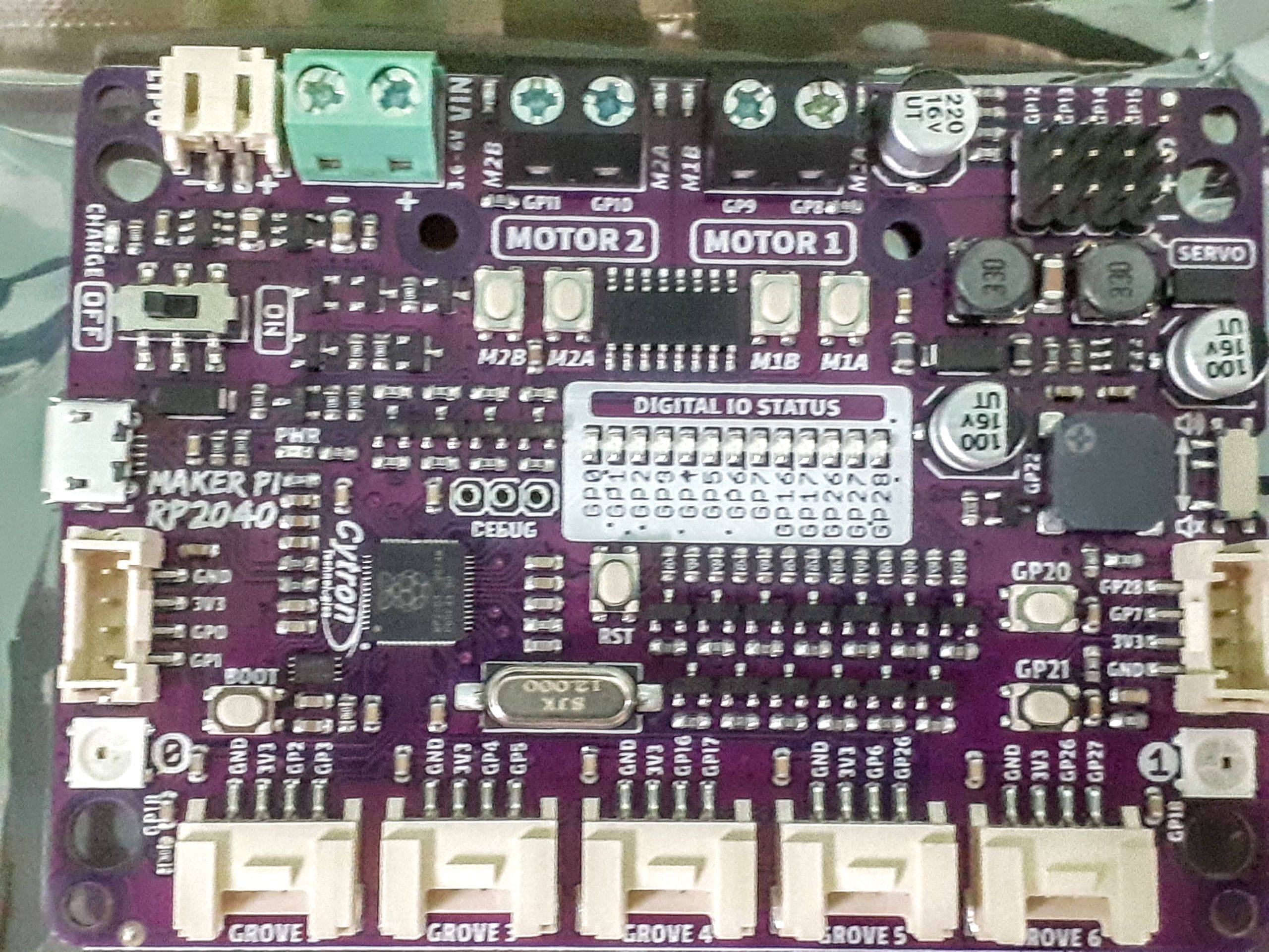
Cytron Technologies has done it again, this time by releasing an in-house designed complete robotics controller board, based on the brand new RP2040 MCU from the Raspberry Pi Foundation.
This post will be part one of a detailed look at this new product.. So, as it is an introduction, lets get some technical specs and features…
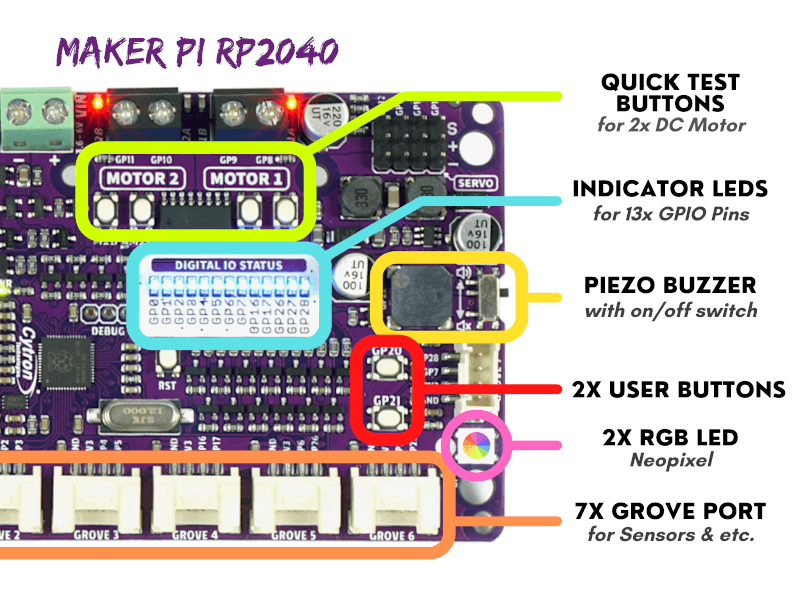
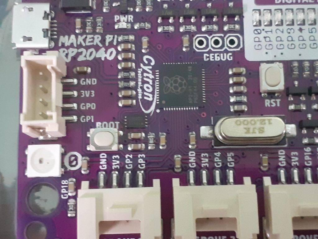
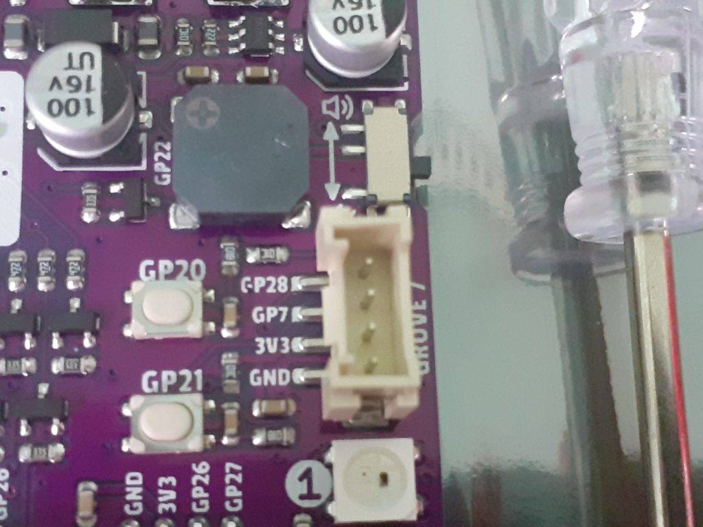
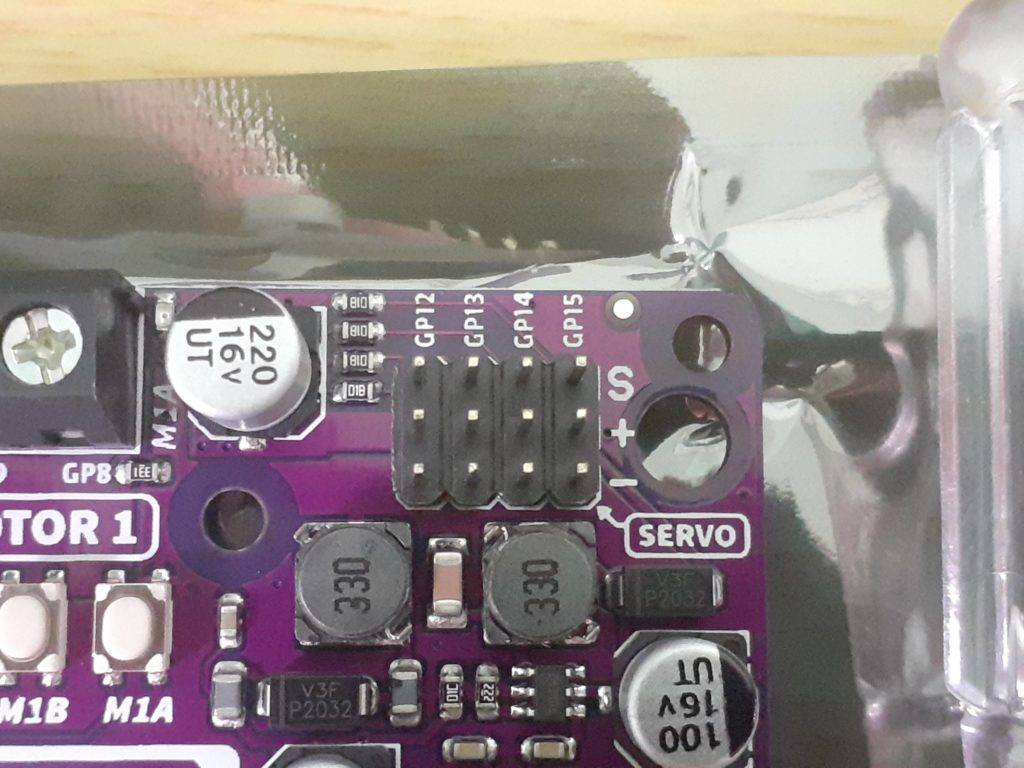
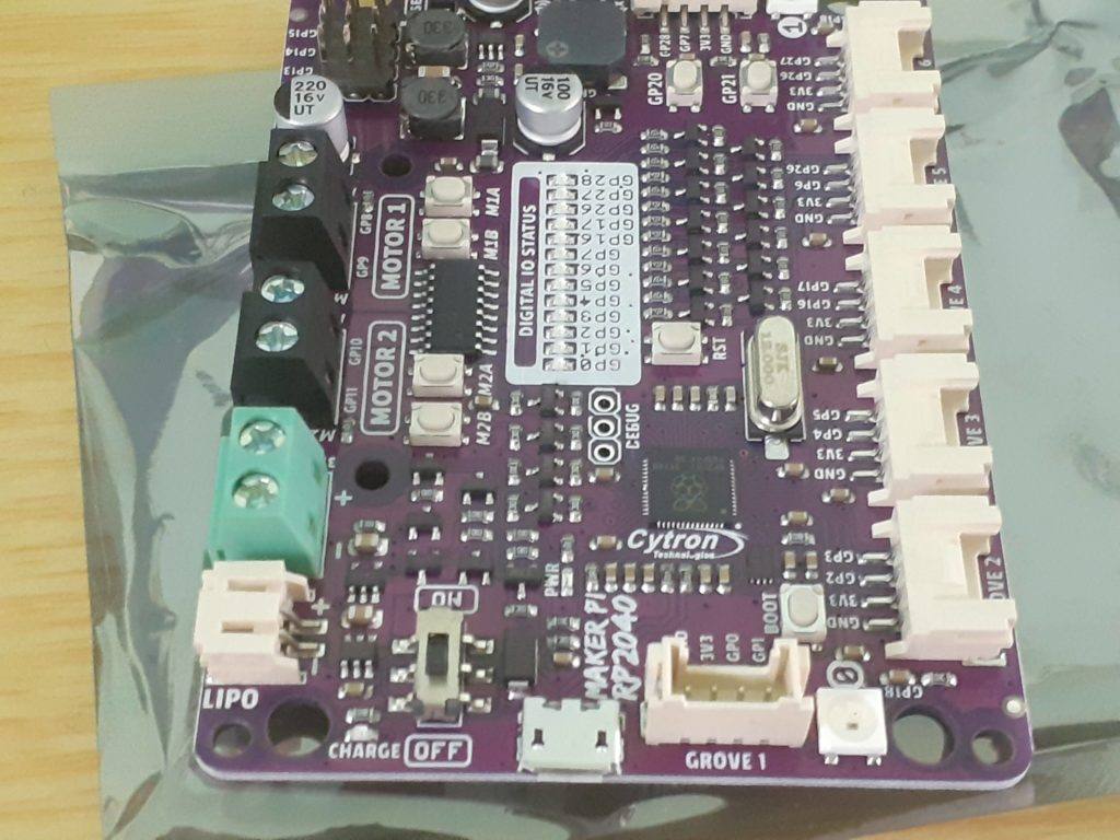
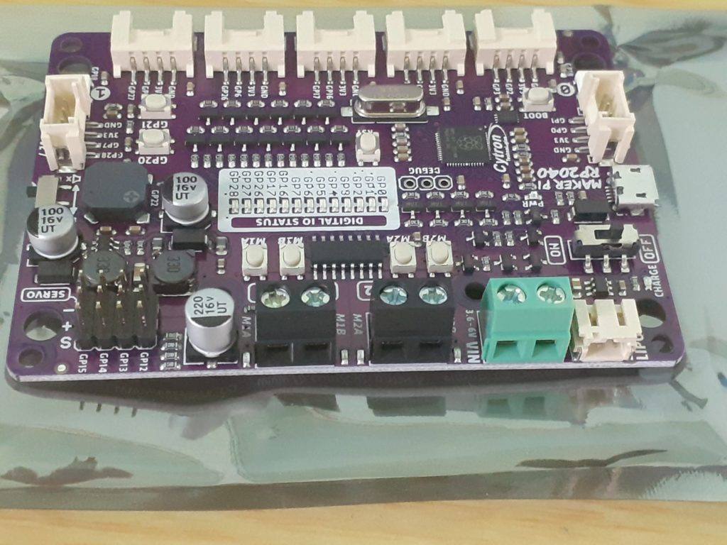
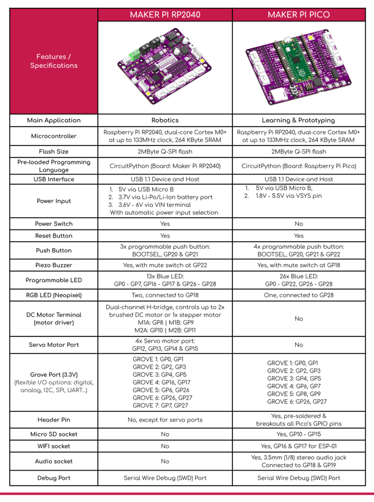
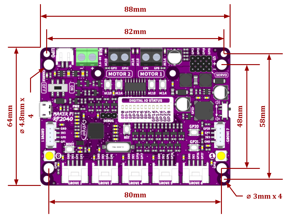
Cytron Maker Pi RP2040 features the first micro-controller designed by Raspberry Pi – RP2040, embedded on a robot controller board. The board also comes with dual channel DC motor driver, 4 servo motor ports and 7 Grove I/O connectors, ready for your next DIY robot / motion control project. Now you can build robot, while trying out the new RP2040 chip.
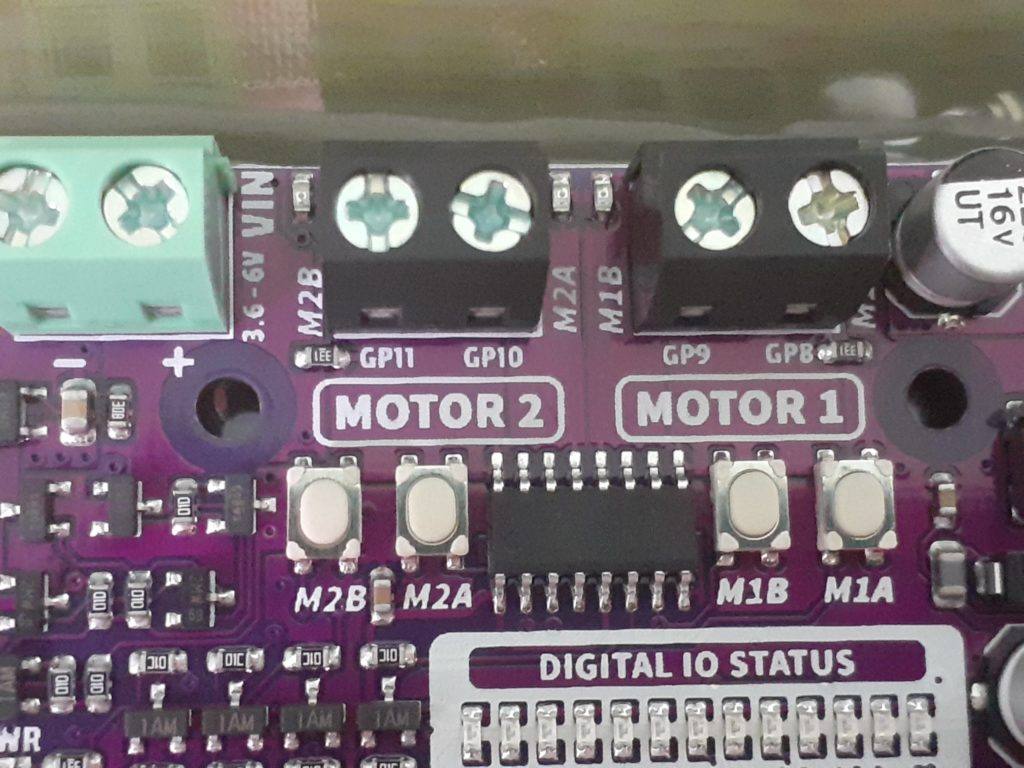
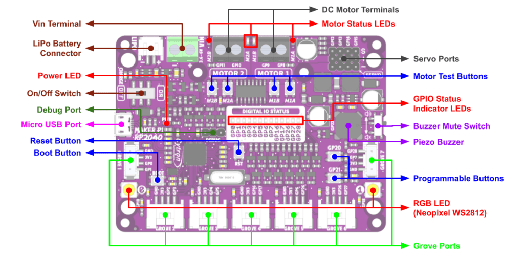
The DC motor driver onboard is able to control 2x brushed DC motors or 1x bipolar/unipolar stepper motor rated from 3.6V to 6V, providing up to 1A current per channel continuously. The built-in Quick Test buttons and motor output LEDs allow functional test of the motor driver in a quick and convenient way, without the need of writing any code. Vmotor for both DC and servo motors depends on the input voltage supplied to the board.
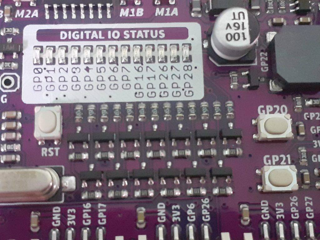
ker Pi RP2040 features all the goodness of Cytron’s Maker series products. It too has lots of LEDs useful for troubleshooting (& visual effects), is able to make quite some noise with the onboard piezo buzzer and comes with push buttons ready to detect your touch.
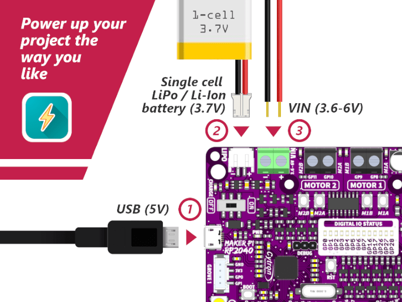
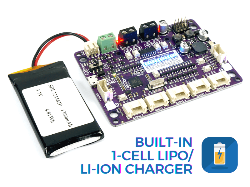
There are three ways to supply power to the Maker Pi RP2040 – via USB (5V) socket, with a single cell LiPo/Li-Ion battery or through the VIN (3.6-6V) terminals. However only one power source is needed to power up both controller board and motors at a time. Power supply from all these power sources can all be controlled with the power on/off switch onboard.
Cytron Maker Pi RP2040 is basically the Raspberry Pi Pico + Maker series’ goodness + Robot controller & other useful features. Therefore this board is compatible with the existing Pico ecosystem. Software, firmware, libraries and resources that are developed for Pico should work seamlessly with Cytron Maker Pi RP2040 too.
CircuitPython is preloaded on the Maker Pi RP2040 and it runs a simple demo program right out-of-the-box. Connect it to your computer via USB micro cable and turn it on, you will be greeted by a melody tune and LEDs running light. Press GP20 and GP21 push buttons to toggle the LEDs on/off, while controlling any DC and servo motors connected to it to move and stop. With this demo code, you get to test the board the moment you receive it!
 Out-of-the-box Demo for Cytron Maker Pi RP2040

 This demo code is written in CircuitPython and it serves
 as an easy quality check when you first receive the board.
 #
 It plays a melody upon power up (slide power switch to ON)
 and shows running lights (blue LEDs) at the same time.
 Then the two RGB LEDs will animate the colors, while the
 program checking push buttons' state, repeatedly.

 Press GP20 button to play a short melody, lights up all
 blue LEDs, move servo motors to 0 degree and run DC motors
 at 50% and -50% speeds.
 Press GP21 button to play another melody, turn off all blue
 LEDs, move servo motors to 180 degree & brake DC motors.

 Maker Pi RP2040 also has four DC motors quick test buttons
 built-in. You may press the onboard M1A, M1B, M2A or M2B
 push buttons to run your motors without writing any code.
 #
 More info:
 http://www.cytron.io/p-maker-pi-rp2040
 https://circuitpython.org/board/raspberry_pi_pico
 #
 Email: support@cytron.io
 *
 import board
 import digitalio
 import neopixel
 import simpleio
 import time
 import pwmio
 from adafruit_motor import servo, motor
 Initialize LEDs
 LEDs placement on Maker Pi RP2040
 LED_PINS = [board.GP0,
             board.GP1,
             board.GP2,
             board.GP3,
             board.GP4,
             board.GP5,
             board.GP6,
             board.GP7,
             board.GP16,
             board.GP17,
             board.GP26,
             board.GP27,
             board.GP28]
 LEDS = []
 for pin in LED_PINS:
     # Set pins as digital output
     digout = digitalio.DigitalInOut(pin)
     digout.direction = digitalio.Direction.OUTPUT
     LEDS.append(digout)
 Initialize Neopixel RGB LEDs
 pixels = neopixel.NeoPixel(board.GP18, 2)
 pixels.fill(0)
 Melody
 MELODY_NOTE = [659, 659, 0, 659, 0, 523, 659, 0, 784]
 MELODY_DURATION = [0.15, 0.15, 0.15, 0.15, 0.15, 0.15, 0.15, 0.15, 0.2]
 Define pin connected to piezo buzzer
 PIEZO_PIN = board.GP22
 Initialize buttons
 btn1 = digitalio.DigitalInOut(board.GP20)
 btn2 = digitalio.DigitalInOut(board.GP21)
 btn1.direction = digitalio.Direction.INPUT
 btn2.direction = digitalio.Direction.INPUT
 btn1.pull = digitalio.Pull.UP
 btn2.pull = digitalio.Pull.UP
 Initialize servos
 50% duty cycle: 2**15 = 32768 = 1/2 of 65536 (16-bit)
 servo_motors = []  # create an array and add servo objects.
 servo_motors.append(servo.Servo(pwmio.PWMOut(board.GP12, duty_cycle=215, frequency=50))) servo_motors.append(servo.Servo(pwmio.PWMOut(board.GP13, duty_cycle=215, frequency=50)))
 servo_motors.append(servo.Servo(pwmio.PWMOut(board.GP14, duty_cycle=215, frequency=50))) servo_motors.append(servo.Servo(pwmio.PWMOut(board.GP15, duty_cycle=215, frequency=50)))
 Initialize DC motors
 m1a = pwmio.PWMOut(board.GP8, frequency=50)
 m1b = pwmio.PWMOut(board.GP9, frequency=50)
 motor1 = motor.DCMotor(m1a, m1b)
 m2a = pwmio.PWMOut(board.GP10, frequency=50)
 m2b = pwmio.PWMOut(board.GP11, frequency=50)
 motor2 = motor.DCMotor(m2a, m2b)
 -------------------------------------------------
 ON START: Show running light and play melody
 -------------------------------------------------
 for i in range(len(LEDS)):
     LEDS[i].value = True
 if i < len(MELODY_NOTE):     # Play melody tones     simpleio.tone(PIEZO_PIN, MELODY_NOTE[i], duration=MELODY_DURATION[i]) else:     # Light up the remainding LEDs     time.sleep(0.15)
 Turn off LEDs one-by-one very quickly
 for i in range(len(LEDS)):
     LEDS[i].value = False
     time.sleep(0.02)
 color = 0
 state = 0
 -------------------------------------------------
 FOREVER LOOP: Check buttons & animate RGB LEDs
 -------------------------------------------------
 while True:
 # Check button 1 (GP20) if not btn1.value:  # button 1 pressed     # Light up all LEDs     for i in range(len(LEDS)):         LEDS[i].value = True     # Move servos to 0 degree     for i in range(len(servo_motors)):         servo_motors[i].angle = 0     # Move motors at 50% speed     motor1.throttle = 0.5  # motor1.throttle = 1 or -1 for full speed     motor2.throttle = -0.5     # Play tones     simpleio.tone(PIEZO_PIN, 262, duration=0.1)     simpleio.tone(PIEZO_PIN, 659, duration=0.15)     simpleio.tone(PIEZO_PIN, 784, duration=0.2) # Check button 2 (GP21) elif not btn2.value:  # button 2 pressed     # Turn off all LEDs     for i in range(len(LEDS)):         LEDS[i].value = False     # Move servos to 180 degree     for i in range(len(servo_motors)):         servo_motors[i].angle = 180     # Brake motors     motor1.throttle = 0  # motor1.throttle = None to spin freely     motor2.throttle = 0     # Play tones     simpleio.tone(PIEZO_PIN, 784, duration=0.1)     simpleio.tone(PIEZO_PIN, 659, duration=0.15)     simpleio.tone(PIEZO_PIN, 262, duration=0.2) # Animate RGB LEDs if state == 0:     if color < 0x101010:         color += 0x010101   # increase rgb colors to 0x10 each     else:         state += 1 elif state == 1:     if (color & 0x00FF00) > 0:         color -= 0x000100   # decrease green to zero     else:         state += 1 elif state == 2:     if (color & 0xFF0000) > 0:         color -= 0x010000   # decrease red to zero     else:         state += 1 elif state == 3:     if (color & 0x00FF00) < 0x1000:         color += 0x000100   # increase green to 0x10     else:         state += 1 elif state == 4:     if (color & 0x0000FF) > 0:         color -= 1          # decrease blue to zero     else:         state += 1 elif state == 5:     if (color & 0xFF0000) < 0x100000:         color += 0x010000   # increase red to 0x10     else:         state += 1 elif state == 6:     if (color & 0x00FF00) > 0:         color -= 0x000100   # decrease green to zero     else:         state += 1 elif state == 7:     if (color & 0x00FFFF) < 0x001010:         color += 0x000101   # increase gb to 0x10     else:         state = 1 pixels.fill(color)  # fill the color on both RGB LEDs # Sleep to debounce buttons & change the speed of RGB color swipe time.sleep(0.05)
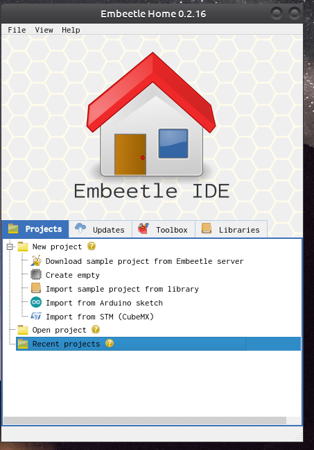
So you have finally decided to give the Embeetle IDE a try, I mean, why not, you have nothing to loose right ? After starting the IDE, you get to this screen…
The Embeetle IDE Home Screen
You are presented with many different options, but which one should you choose… Many of you will choose “Create Empty”, but be warned: This is not what you want. For those of us that come from standard IDE software, especially the Arduino IDE, we believe that the source files should only contain void setup() and void loop()… and then we can continue with our coding …
This is however very very wrong… Many IDE’s hide most of the code from you, in an effort to make it “easier to use”. Embeetle does not do that. So unless you are very confident in your C/C++ skills, Do not choose this option.
Embeetle requires you to use real C++ when you write code, so while you can still do all the things you are used to do with “Arduino C” there will definitely be a few differences that you need to take account of. Professional developers will not have a problem however, as you are already used to declaring function prototypes etc…
So where do we start then?
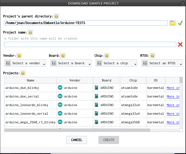
Select the “Download Sample Project from Embeetle Server” option.
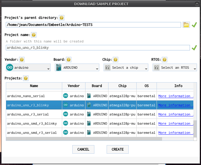
After a few seconds, you will be presented with this screen:
Now, we have to mention another point about Embeetle. Embeetle does not only support Arduino Boards. Embeetle supports many other devices, and the list is growing.. so you will have to choose your device… So as an example, I will show you how to load the standard “blink” sketch on the Arduino Uno R3 ..
After selecting a Vendor and a Board, and some scrolling, I have selected the Arduino Uno R3 Blinky sketch. Go ahead and click on the “Create” button. Embeetle will now generate your sketch, generate a makefile and all the other needed files that are normally hidden away from you, and then open the editor window…
An important note here:
When you have installed Embeetle for the first time, you may not have all the required toolchains and other drivers installed on your computer. Usually, this can be a real pain to figure out. But, once again, Embeetle will take care of it… with a little bit of your help, of course… You may be presented with a small window, asking you to choose toolchain and or linker applications. Click on the drop-down menu, and select the option in GREEN. nothing else, and click apply… Embeetle will automatically download and install it, no further actions required from you!~ Easy, is it not ?
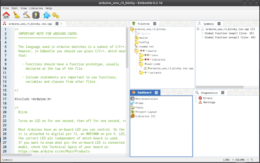
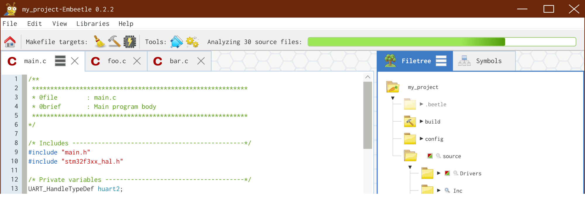
The Embeetle Editor
So now, the Editor has opened, and you are all confused, as it does not look anything like what you are used to, so what do we do now ? Lets look around the IDE quickly…
At the top left, we have a menu bar, and below that, a few tool buttons, not many, as we dont need all of those cluttered buttons anyway… The most important here is : The Broom : Cleans your project The Hammer: Builds ( compiles ) your project The Chip : Flashes the project onto the device The Serial Port: Opens the Serial Monitor
In the center column, we have the File tree, showing all the files your project are using, with green dots in front, meaning in use, and red meaning not used,
and directly below that, the Dashboard…
This is where you will select your tools, as well as the serial port your device is connected to…
On the Far right, you have a symbol table, and some diagnostics ( but this is usually for the more advanced users, although everyone can benefit from using how to use these
Connecting your Device
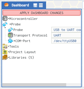
Let us connect our device. 1.) Start by plugging you Arduino Uno R3 into the USB Cable, and connecting the cable to your computer. 2.)In the Dashboard window, Click on Probe -> Com-Port -> Select and choose your port ( on Ubuntu, it wil be /dev/ttyUSB0 or similar, on Windows it may be com3 or similar
After selecting your device communications port
3.) A red warning will now appear, “APPLY DASHBOARD CHANGES”. Click on this to confirm your changes. 4.) your device are now connected, and you can start coding…
Let us have a quick look at the coding style, as is is quite different from what you would use in an the Arduino IDE
The most important change is that you will need to declare function “prototypes” This is normal in standard C/C++ but is not needed in the Arduino IDE…
this means doing this:
void setup(); void loop();
You will have to declare any other functions that you write on your own as well… including their datatypes, and any parameters that they require… Once again, this is usually not a problem for the casual home user, and the professional developers already know what this means…
The complete sketch is below
/*
  IMPORTANT NOTE FOR ARDUINO USERS
  ================================

  The language used in Arduino sketches is a subset of C/C++.
  However, in Embeetle you should use plain C/C++, which means
  that:

    - Functions should have a function prototype, usually
      declared at the top of the file.

    - Include statements are important to use functions,
      variables and classes from other files.

*/

#include <Arduino.h>

/*
  Blink

  Turns an LED on for one second, then off for one second, repeatedly.

  Most Arduinos have an on-board LED you can control. On the UNO, MEGA and ZERO
  it is attached to digital pin 13, on MKR1000 on pin 6. LED_BUILTIN is set to
  the correct LED pin independent of which board is used.
  If you want to know what pin the on-board LED is connected to on your Arduino
  model, check the Technical Specs of your board at:
  https://www.arduino.cc/en/Main/Products

  modified 8 May 2014
  by Scott Fitzgerald
  modified 2 Sep 2016
  by Arturo Guadalupi
  modified 8 Sep 2016
  by Colby Newman

  This example code is in the public domain.

  http://www.arduino.cc/en/Tutorial/Blink
*/

// the setup function runs once when you press reset or power the board

void setup();

void loop();

void setup() {
  // initialize digital pin LED_BUILTIN as an output.
  pinMode(LED_BUILTIN, OUTPUT);
}

// the loop function runs over and over again forever
void loop() {
  digitalWrite(LED_BUILTIN, HIGH);   // turn the LED on (HIGH is the voltage level)
  delay(1000);                       // wait for a second
  digitalWrite(LED_BUILTIN, LOW);    // turn the LED off by making the voltage LOW
  delay(1000);                       // wait for a second
}

Now, let us build and flash the code to the device

Click on the hammer tool...
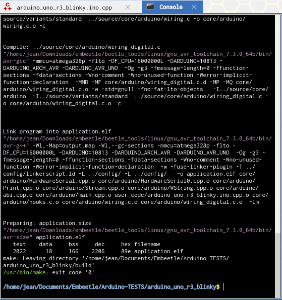
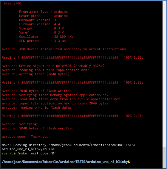
Embeetle will compile and build your code, and inform you at the bottom of the console if all went well. If it did, click on the Chip Tool to Flash it to your device
Once again, Embeetle will inform you of the status of the Upload, and if you did everything correctly, the led on the UNO will start flashing….
In our next article, we will look at how to use the Library manager. This is definitely one of the most powerful features of Embeetle, only to be surpassed by the source analyser and the symbol generator.. but more on that later.
Official Arduino IDE support for the Raspberry Pi Pico is finally here. It took a while,and those of us that could not be bothered with Micro-Python, or complex C tool-chains, can finally take out Pico’s out of the drawer, and start putting them through their paces…
This is also an excellent opportunity to really push the Maker Pi Pico, from Cytron Technologies, so its limits, as the rich library environment from the Arduino IDE, will definitely allow quick and fast access to all of the Maker Pi Pico’s built in hardware…
Adding Pico Support to the Arduino IDE
Before we can use the Pico with the Arduino IDE, we first have to add support for the board into the Arduino IDE. This is done with the Boards Manager, Although very easy, there are however a few things that you have to take note of. You have to remove support for ALL other Pi Pico boads packages that you may have installed into the Arduino IDE, previously, as well as any additional board url’s in the preferences menu…
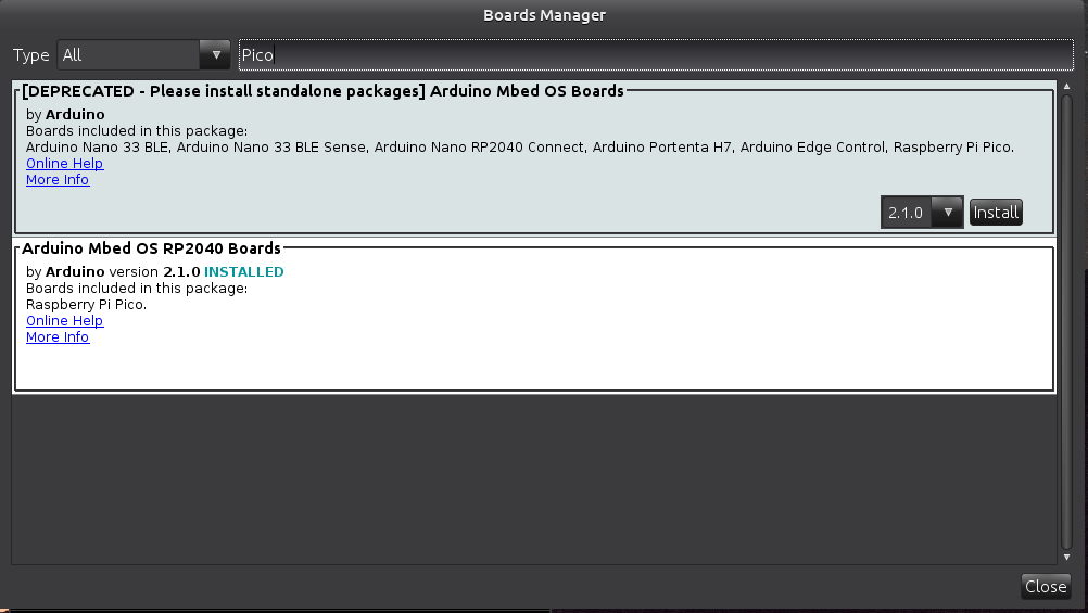
Then, after removing that all, restart your Arduino IDE, go to the Tools menu, and then Boards _> Boards Manager. Type Pico into the search box. Press Enter…
Select and Install the “Arduino MBed OS RP2040 Boards”… Wait for this to install, It will take a while, depending on your internet speed…
When this is finished, we can configure your Pico board.
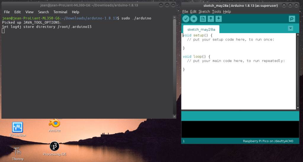
Please Note: On Linux operating systems, like Ubuntu, you will have to perform an additional step. This is because of permissions on hardware devices. You will have to start the Arduino IDE as a superuser, i.e. with sudo, from the command line, and then install the RP2040 support AS WELL…. Once that is done, keep the IDE open, and continue with the rest of this guide….
To do this do the following:
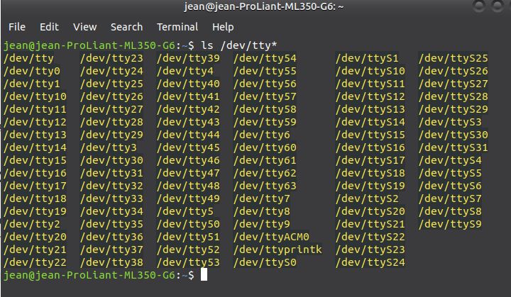
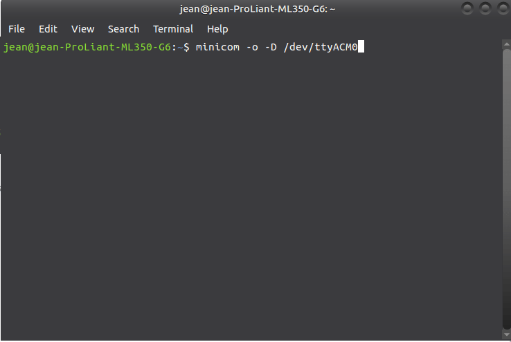
Open a Terminal Window go to the Arduino installation folder, on my system ( Ubuntu 20.04 LTS it is /home/jean/Downloads/arduino-1.8.13 ) and then issue the command $ sudo ./arduino
You will get a similar display as above … Now open the boards manager again, and install the “Arduino MBed OS RP2040 Boards” board support files ….
Continue to the next step below…
Uploading your first sketch to the Pico
DO NOT PLUG THE PICO INTO A USB PORT YET
With the Arduino IDE Open, ( As superuser on Ubuntu or other Linux), open a blank sketch, and select the Raspberry Pi Pico, from the Boards menu under Tools ( It will be under Arduino MBed OS RP2040)
Open a blank sketch, or the standard blink example sketch.
Now, while holding the BOOTSEL button on the PICO pressed in, plug in your PICO, and then release the button. The Pico will open a File Dialog on your computer, similar to when you loaded Micro-Python Support. Do NOT search for a Com port at this stage, it will not exist yet !
Ignore the File window, and click on the upload button in the Arduino IDE. The sketch will upload, and the PICO will reset automatically.
UBUNTU or other Linux Users, If this was successful, you can close the Arduino IDE as superuser, and open your standard Arduino IDE.
After this step, you will not have to hold down BOOTSEL every time to upload a sketch, even if you have unplugged the PICO, but you will have to select a valid COM port in the Arduino IDE… On Ubuntu, it will be /dev/ttyACM0 or similar, please look in the ports menu under tools in the Arduino IDE.
You can now make use of all the existing Arduino libraries with your Raspberry Pi Pico…
A few points to note:
I2C is on GP6 (SCL) and GP7 (SDA) -> confirmed as definitely working ( i2c1, not i2c0 !) SPI is as mentioned in this post -> GitHUB ( Please note that there seem to still be a bit of teething problems, your mileage may vary )
A few months ago, I was approached by one of the Embeetle team members, to give some feedback on a new IDE that they were working on. I decided to do that, and what a good decision it was… I am not your average developer, and as such, doesn’t spend a lot of my time on fancy IDE software. I rather focus on getting things done… I have been outgrowing the popular Arduino IDE for a long time now, as it is quite limiting in some areas, but stuck to it, as it sort of still serves a purpose in my style of development…
Embeetle changed that outlook completely, and I was hooked almost immediately. Working closely with the development team over the last few months to add Arduino support to Embeetle was also extremely rewarding, especially being able to use bleeding edge software, and actively participating in helping find bugs and discussing new ways to implement new features.
The support team is great, and bugs gets fixed extremely fast, only one advantage of a small dedicated team of programmers, that are focused on quality…
With the now public release of Embeetle, with Arduino Support, a brand new serial monitor, and also a very intuitive library manager, I really hope that more users will give this new IDE a try and hopefully, like me, become hooked and stay with it in the long run…
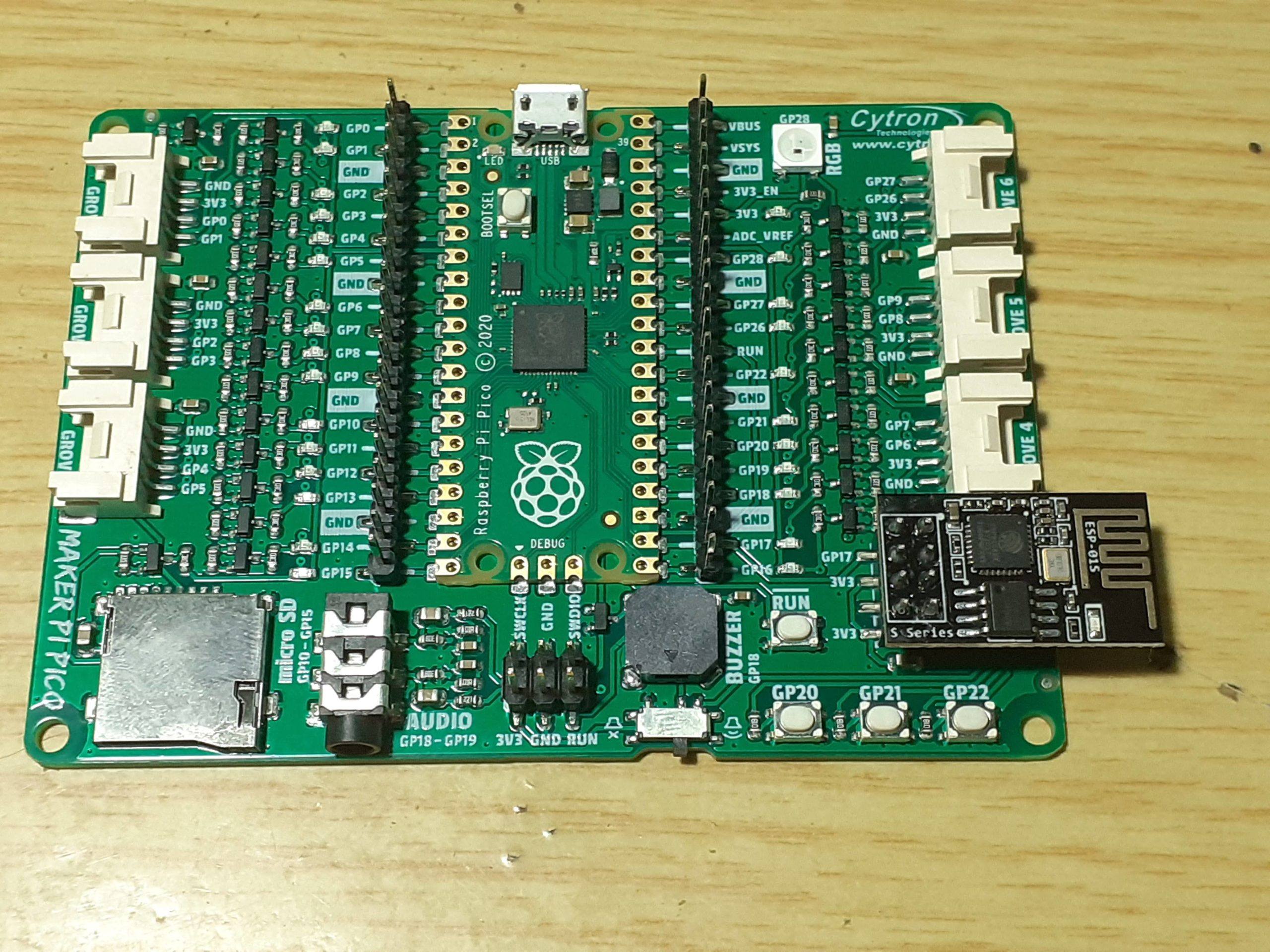
It has been a while since my last post, most of which has been spent dealing with other things, as well as waiting for electronics modules to arrive from overseas. A lot of my time has also been spent on getting to grips with the Raspberry Pi Pico, and in particular, the Maker Pi Pico, from Cytron Technologies. This has been an experience with quite a lot of mixed feelings… As Usual, Cytron has done an excellent job with the development board, which, while apparently still in Beta, seems to be rock solid. Most of my frustration came from the “patchy” C/C++ support for the Pi Pico (Yes, I know there are great support, BUT it is not exactly user friendly 🙂 ). That left me with MicroPython, which although I am fluent, are not my goto language…
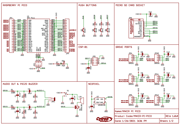
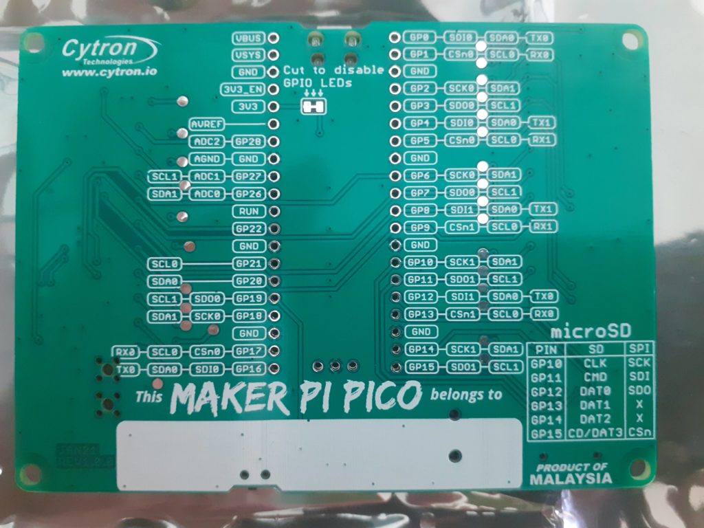
Lets get back on track though… The Maker Pi Pico has built in support for an ESP01/ESP01S Module. Lets look at the schematic….
Maker Pi Pico Schematic
As we can see, Cytron has provided us with access to Tx (GP17) and Rx(GP16) directly on the Pi Pico. Power (+3.3v) and Ground are connected as well… On this version of the board, no access to IO0,IO2 and the Reset Pin for the ESP01/ESP01S was provided… Maybe this will change in future…?
I have used the standard AT command firmware that comes pre-loaded onto the ESP01/S module. This allows you to send AT commands to the ESP01 Module to control it. It is also possible to setup a transparent WiFi “channel” to communicate between Pico and a remote application , making it possible to control Pico remotely. I have however not prepared and example of that for release yet….
MicroPython Code to communicate with ESP01 from Maker Pi Pico
import uos
from machine import UART, Pin
import utime
"""
ESPRESSIF AT Command Set
https://docs.espressif.com/projects/esp-at/en/latest/AT_Command_Set/
"""
print()
print("Machine: \t" + uos.uname()[4])
print("MicroPython: \t" + uos.uname()[3])
#indicate program started visually
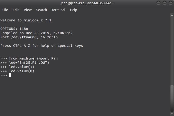
led_onboard = machine.Pin(25, machine.Pin.OUT)
led_onboard.value(0) # onboard LED OFF/ON for 0.5/1.0 sec
utime.sleep(0.5)
led_onboard.value(1)
utime.sleep(1.0)
led_onboard.value(0)
uart0 = UART(0, rx=Pin(17), tx=Pin(16), baudrate=115200)
# NOTE that we explicitly set the Tx and Rx pins for use with the UART
# If we do not do this, they WILL default to Pin 0 and Pin 1
# Also note that Rx and Tx are swapped, meaning Pico Tx goes to ESP01 Rx
# and vice versa.
print(uart0)
def sendCMD_waitResp(cmd, uart=uart0, timeout=2000):
print("CMD: " + cmd)
uart.write(cmd)
waitResp(uart, timeout)
print()
def waitResp(uart=uart0, timeout=2000):
prvMills = utime.ticks_ms()
resp = b""
while (utime.ticks_ms()-prvMills)<timeout:
if uart.any():
resp = b"".join([resp, uart.read(1)])
print("resp:")
try:
print(resp.decode())
except UnicodeError:
print(resp)
sendCMD_waitResp('AT\r\n') #Test AT startup
sendCMD_waitResp('AT+GMR\r\n') #Check version information
#sendCMD_waitResp('AT+RESTORE\r\n') #Restore Factory Default Settings
sendCMD_waitResp('AT+CWMODE?\r\n') #Query the Wi-Fi mode
sendCMD_waitResp('AT+CWMODE=1\r\n') #Set the Wi-Fi mode = Station mode
sendCMD_waitResp('AT+CWMODE?\r\n') #Query the Wi-Fi mode again
#sendCMD_waitResp('AT+CWLAP\r\n', timeout=10000) #List available APs
sendCMD_waitResp('AT+CWJAP="jean_iot","master123abc"\r\n', timeout=5000) #Connect to AP
utime.sleep(1)
sendCMD_waitResp('AT+CIFSR\r\n') #Obtain the Local IP Address
You can now extend and adapt this code to suit your purposes…
The ESP01/ESP01S AT Command Datasheet is available for download here
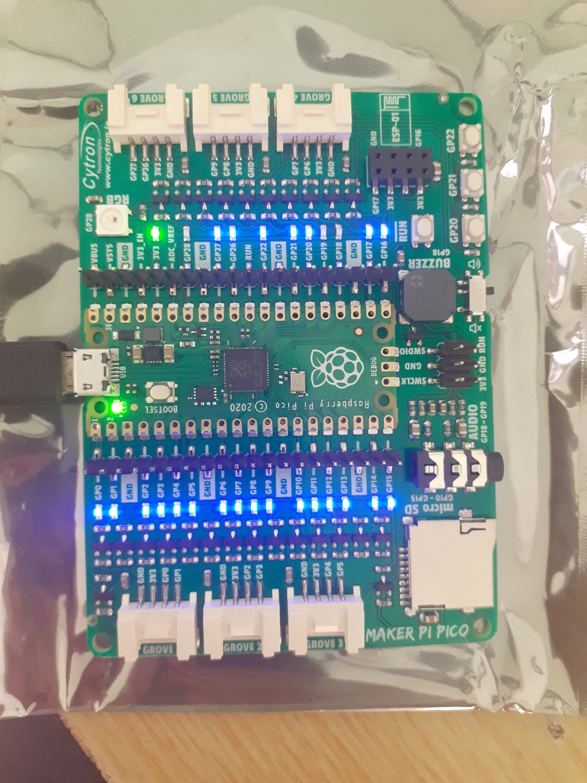
It has been almost a week now since I received my Maker Pi Pico from Cytron Technologies in Malysia. Most of this time has been spent getting to know the RP2040 Microchip, and how to effectively program it. Cytron has done an excellent job being very quick to market with a development board based on the RPi Pico, as well as providing a very good starting foundation to new Pico users ( which I believe is all of us, at least at this stage 🙂 )
It is super easy to put your Maker Pi Pico into Upload Mode. No need to plug and unplug your USB Cable. – Push and hold the RUN Button ( Located on the Bottom Right, Above the GP20 Push Button) . – While holding RUN pressed, press the BOOTSEL button on the Pico, and keep it pressed. – Release RUN and then release BOOTSEL.
You are now in BOOTSEL Mode. You can donload the official Micropython .uf2 file from the link below, or from the Raspberry Pi Website. It is also possible to install Micropython directly from inside the Thonny Python IDE.
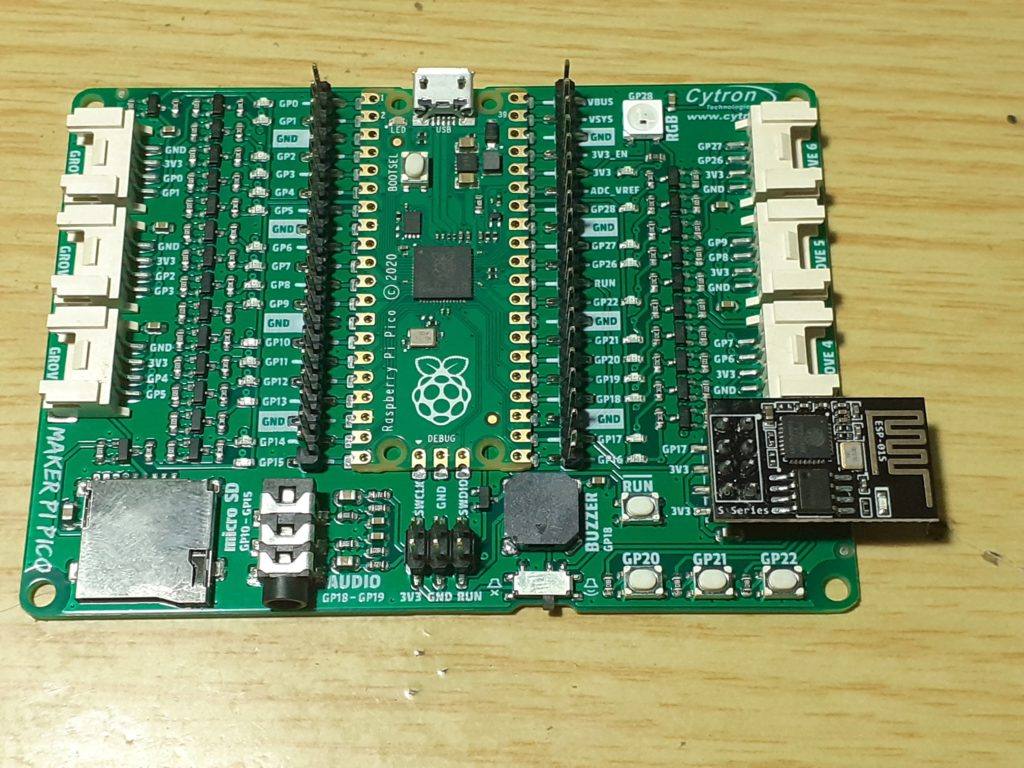
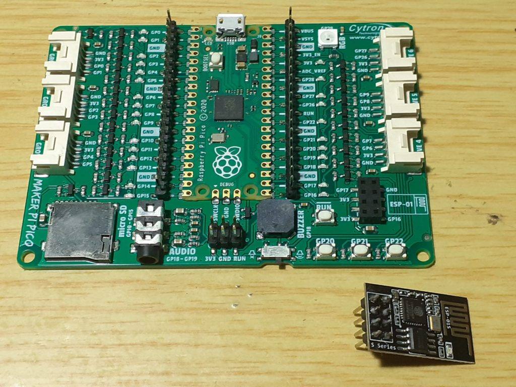
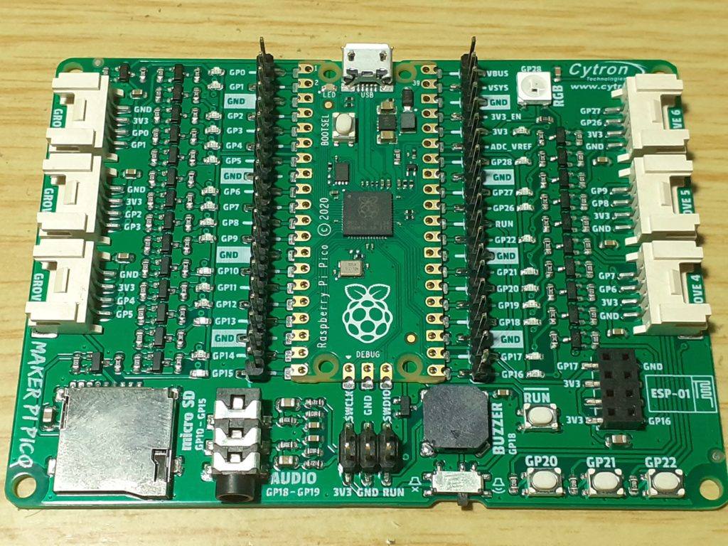
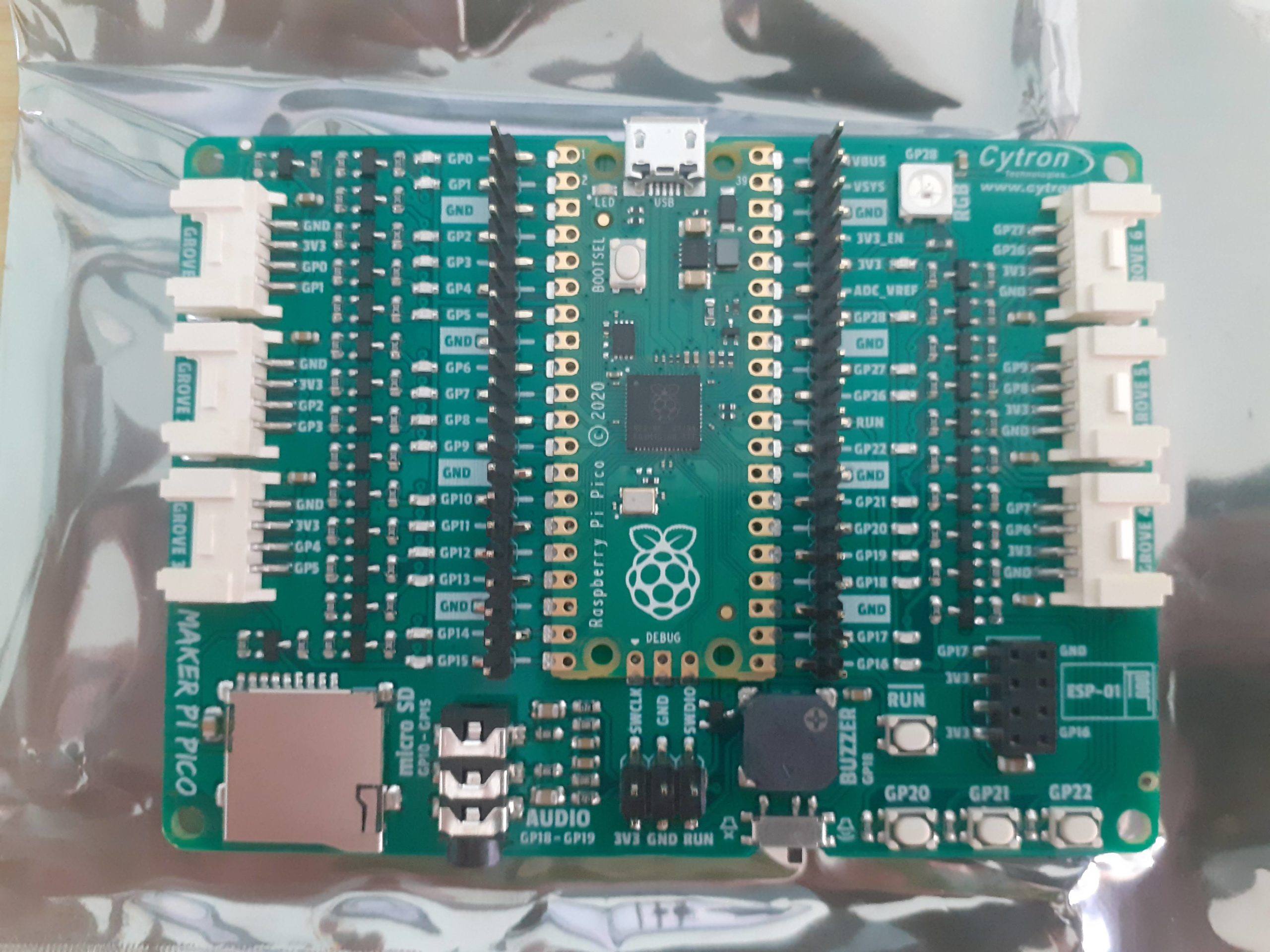
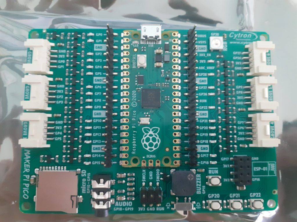
While everybody in the Maker Community are slowly coming to terms with the release of the RPi Pico (The new development board based on the RP2040 by the Raspberry Pi Foundation) a few days ago, I got my hands on one of the first maker-friendly development boards designed with the Pico in mind. The Maker Pi Pico, made by Cytron Technologies, definitely makes it very easy to get started with the new RPi Pico.
A one-sided SMD development board, packed with useful peripherals, in a 93.98 x 68.58mm form factor, with the following components already onboard:
Access to all Raspberry Pi Pico’s pins on two 20 ways pin headers
LED indicators on all GPIO pins
3x programmable push button (GP20-22)
1x RGB LED – NeoPixel (GP28)
1x Piezo buzzer (GP18)
1x 3.5mm stereo audio jack (GP18-19)
1x Micro SD card slot (GP10-15)
1x ESP-01 socket (GP16-17)
6x Grove ports
Over the next few days, I will go into some of this exiting new development board`s features, as well as show you how to program it using Micropython as well as C/C++
UPDATE 5 February 2021
Although the Raspberry Pi Foundation has provided excellent documentation on programming the PICO with C/C++, I will not do any review of that here at this time. The reasons being the following:
1) It seems that PICO was indeed designed as a companion to a Raspberry PI 4B. All the C/C++ tools are geared towards that or Linux. I use Linux in my everyday computing life, but most of you don’t. 2) At the moment, the most reliable way that I can program this board in C/C++ is from the command line. Support for many IDE’s seems to be available. But it is PAINFUL, to say the least. VS Source or CLION or ECLIPSE, neither IDE’s that I like or use, due to their clutter and slow performance / unnecessary complexity etc. 3) It is possible to use MS Windows or a MAC, but same rules apply.
Another reason is that you have to enter BOOTSEL mode each time you want to upload or use a debugger, which, if you don’t have a PI, means another PICO. Plugging and unplugging a USB cable that often can not be good for the connector in the long term.
For these reasons, and to keep it simple and easily understandable for everyone, I shall keep to Micropython for the time being.
Please stay in touch for more updates, and feel free to contact me for more information.
Welcome to Part two of my RPi Pico Series. You can buy yours from Cytron Technologies. In this post, we will look at some more of the features of the board, as well as how to get started using this development board. I will focus on MicroPython in this post, and cover C/C++ in the next post.
But before we do that, lets run over some of the specifications of the board first… The Python Stuff will be at the end of this post…
Board Specifications
Raspberry Pi Pico is a low-cost, high-performance microcontroller board with flexible digital interfaces. Key features include:
RP2040 microcontroller chip designed by Raspberry Pi in the United Kingdom
Dual-core Arm Cortex M0+ processor, flexible clock running up to 133 MHz
264KB of SRAM, and 2MB of on-board Flash memory
Castellated module allows soldering direct to carrier boards
USB 1.1 with device and host support
Low-power sleep and dormant modes
Drag-and-drop programming using mass storage over USB
8 × Programmable I/O (PIO) state machines for custom peripheral support
Utilities
What is on your Pico?
If you have forgotten what has been programmed into your Raspberry Pi Pico, and the program was built using our Pico C/C++ SDK, it will usually have a name and other useful information embedded into the binary. You can use the Picotool command line utility to find out these details. Full instructions on how to use Picotool to do this are available in the ‘getting started‘ documentation.
It is possible to use one Raspberry Pi Pico to debug another Pico. This is possible via picoprobe, an application that allows a Pico to act as a USB → SWD and UART converter. This makes it easy to use a Pico on non-Raspberry Pi platforms such as Windows, Mac, and Linux computers where you don’t have GPIOs to connect directly to your Pico. Full instructions on how to use Picoprobe to do this are available in the ‘getting started‘ documentation.
Pico’s BOOTSEL mode lives in read-only memory inside the RP2040 chip, and can’t be overwritten accidentally. No matter what, if you hold down the BOOTSEL button when you plug in your Pico, it will appear as a drive onto which you can drag a new UF2 file. There is no way to brick the board through software. However, there are some circumstances where you might want to make sure your Flash memory is empty. You can do this by dragging and dropping a special UF2 binary onto your Pico when it is in mass storage mode.
/**
 * Copyright (c) 2020 Raspberry Pi (Trading) Ltd.
 *
 * SPDX-License-Iden
/**
 * Copyright (c) 2020 Raspberry Pi (Trading) Ltd.
 *
 * SPDX-License-Identifier: BSD-3-Clause
 */

// Obliterate the contents of flash. This is a silly thing to do if you are
// trying to run this program from flash, so you should really load and run
// directly from SRAM. You can enable RAM-only builds for all targets by doing:
//
// cmake -DPICO_NO_FLASH=1 ..
//
// in your build directory. We've also forced no-flash builds for this app in
// particular by adding:
//
// pico_set_binary_type(flash_nuke no_flash)
//
// To the CMakeLists.txt app for this file. Just to be sure, we can check the
// define:
#if !PICO_NO_FLASH
#error "This example must be built to run from SRAM!"
#endif

#include "pico/stdlib.h"
#include "hardware/flash.h"
#include "pico/bootrom.h"

int main() {
    flash_range_erase(0, PICO_FLASH_SIZE_BYTES);
    // Leave an eyecatcher pattern in the first page of flash so picotool can
    // more easily check the size:
    static const uint8_t eyecatcher[FLASH_PAGE_SIZE] = "NUKE";
    flash_range_program(0, eyecatcher, FLASH_PAGE_SIZE);

    // Flash LED for success
    gpio_init(PICO_DEFAULT_LED_PIN);
    gpio_set_dir(PICO_DEFAULT_LED_PIN, GPIO_OUT);
    for (int i = 0; i < 3; ++i) {
        gpio_put(PICO_DEFAULT_LED_PIN, 1);
        sleep_ms(100);
        gpio_put(PICO_DEFAULT_LED_PIN, 0);
        sleep_ms(100);
    }

    // Pop back up as an MSD drive
    reset_usb_boot(0, 0);
}tifier: BSD-3-Clause
 */

// Obliterate the contents of flash. This is a silly thing to do if you are
// trying to run this program from flash, so you should really load and run
// directly from SRAM. You can enable RAM-only builds for all targets by doing:
//
// cmake -DPICO_NO_FLASH=1 ..
//
// in your build directory. We've also forced no-flash builds for this app in
// particular by adding:
//
// pico_set_binary_type(flash_nuke no_flash)
//
// To the CMakeLists.txt app for this file. Just to be sure, we can check the
// define:
#if !PICO_NO_FLASH
#error "This example must be built to run from SRAM!"
#endif

#include "pico/stdlib.h"
#include "hardware/flash.h"
#include "pico/bootrom.h"

int main() {
    flash_range_erase(0, PICO_FLASH_SIZE_BYTES);
    // Leave an eyecatcher pattern in the first page of flash so picotool can
    // more easily check the size:
    static const uint8_t eyecatcher[FLASH_PAGE_SIZE] = "NUKE";
    flash_range_program(0, eyecatcher, FLASH_PAGE_SIZE);

    // Flash LED for success
    gpio_init(PICO_DEFAULT_LED_PIN);
    gpio_set_dir(PICO_DEFAULT_LED_PIN, GPIO_OUT);
    for (int i = 0; i < 3; ++i) {
        gpio_put(PICO_DEFAULT_LED_PIN, 1);
        sleep_ms(100);
        gpio_put(PICO_DEFAULT_LED_PIN, 0);
        sleep_ms(100);
    }

    // Pop back up as an MSD drive
    reset_usb_boot(0, 0);
}
Getting Started with MicroPython on the RPi Pico
Drag and drop MicroPython
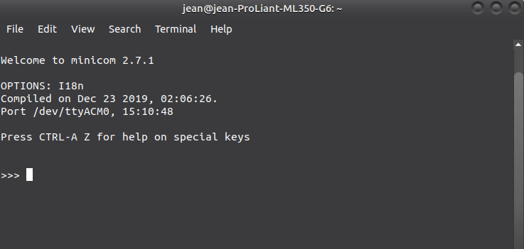
You can program your Pico by connecting it to a computer via USB, then dragging and dropping a file onto it, so we’ve put together a downloadable UF2 file to let you install MicroPython more easily. Following the procedure below, you can install MicroPython onto the Pico in a few seconds…
1. Download and unzip the UF2 file below into a folder on your computer.
2. Hold down the Bootsel button on the Pico, and connect it to a USB cable that was already connected to your computer. ( This means, connect ons side of the usb cable to the computer, but dont connect the Pico yet. then hold down BOOTSEL, and connect the cable to the pico)
3. Now, release the BootSEL button
4. After a few Seconds, you will have a new USB storage device on your computer, called RPI-RP2
5. Drag the UF2 file into this USB Storage device. The Pico will reboot… You have now installed MicroPython on your RPi Pico
It is not often that we get the opportunity to be one of the first people to get our hands onto a new product, So when my friends at Cytron Technologies asked me if I would like to do a review on a new Raspberry Pi product last week, I was definitely interested. Details were few, as the product was still under an NDA, but at last, I got the datasheets and some details on Tuesday, enough to start writing about the new product before the big Launch on Thursday the 21st of January 2021…
So, what am I trying to say? Well, It seems that the Raspberry Pi Foundation has released a new product, and from first impressions, it seems to be a game-changer… Lets not get confused. I am not speaking about a full size Raspberry Pi Board, or the compute module… No, The Pi Foundation has released an RP2040 Microprocessor based development board, in the same form factor as an Arduino Nano.
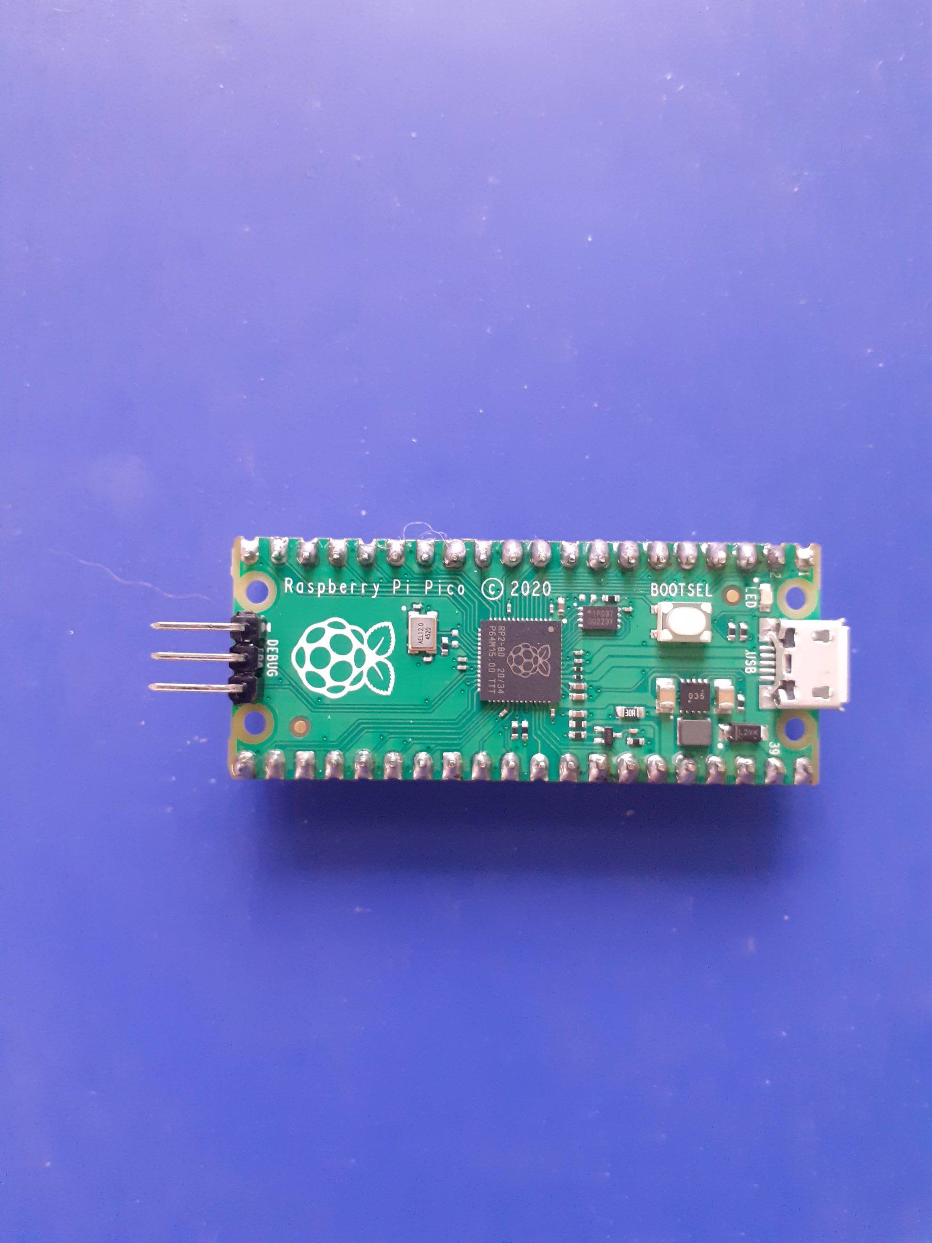
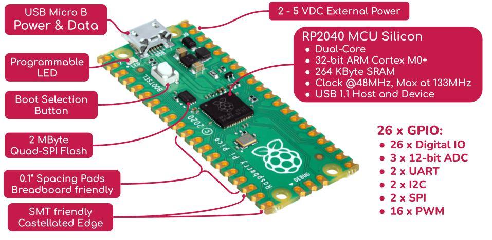
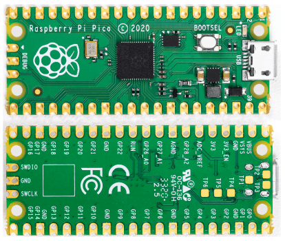
Raspberry Pi Pico Microcontroller Board
This will be an introduction post, and when I receive the device to play with, which will be soon, I will start with a short series on its features and capabilities… For now, lets look at some of the specifications
Front and Back view of the Raspberry Pi Pico
Features:
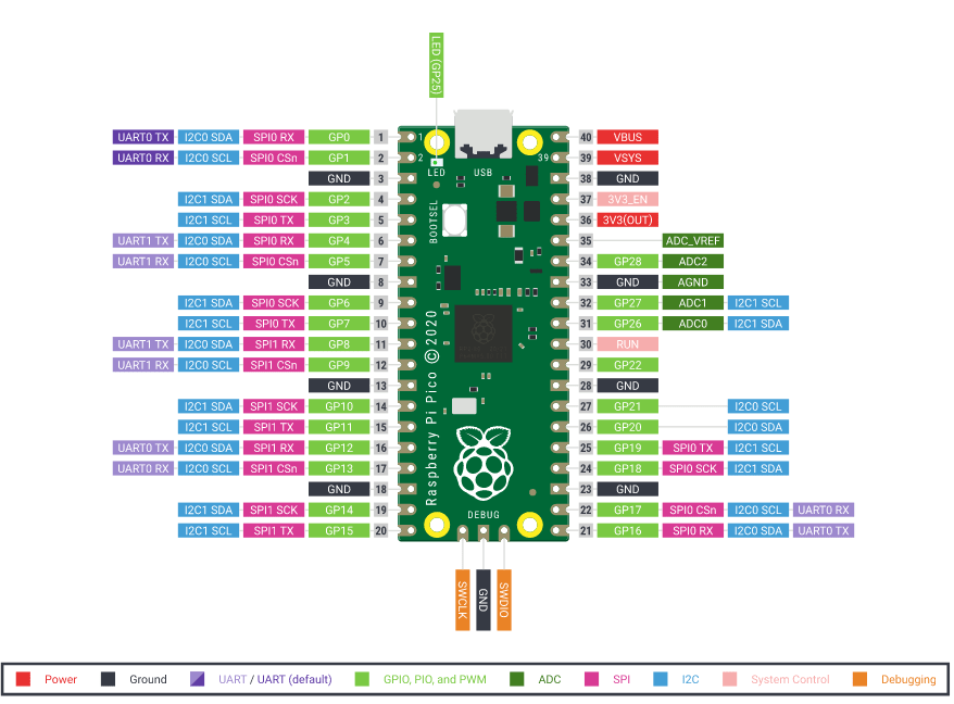
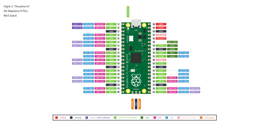
Raspberry Pi Pico has been designed to be a low cost yet flexible development platform for RP2040, with the following key features: • RP2040 microcontroller with 2MByte Flash • Micro-USB B port for power and data (and for reprogramming the Flash) • 40 pin 21×51 ‘DIP’ style 1mm thick PCB with 0.1″ through-hole pins also with edge castellations ◦ Exposes 26 multi-function 3.3V General Purpose I/O (GPIO) ◦ 23 GPIO are digital-only and 3 are ADC capable ◦ Can be surface mounted as a module • 3-pin ARM Serial Wire Debug (SWD) port • Simple yet highly flexible power supply architecture ◦ Various options for easily powering the unit from micro-USB, external supplies or batteries • High quality, low cost, high availability • Comprehensive SDK, software examples and documentation RP2040 key features: (Datasheet available for download at the bottom of this post) • Dual-core cortex M0+ at up to 133MHz ◦ On-chip PLL allows variable core frequency • 264K multi-bank high performance SRAM • External Quad-SPI Flash with eXecute In Place (XIP) • High performance full-crosspoint bus architecture • On-board USB1.1 (device or host) • 30 multi-function General Purpose IO (4 can be used for ADC) ◦ 1.8-3.3V IO Voltage (NOTE Pico IO voltage is fixed at 3.3V) • 12-bit 500ksps Analogue to Digital Converter (ADC) • Various digital peripherals ◦ 2x UART, 2x I2C, 2x SPI, up to 16 PWM channels ◦ 1x Timer with 4 alarms, 1x Real Time Counter • Dual Programmable IO (PIO) peripherals ◦ Flexible, user-programmable high-speed IO ◦ Can emulate interfaces such as SD Card and VGA
Pico provides minimal (yet flexible) external circuitry to support the RP2040 chip (Flash, crystal, power supplies and decoupling and USB connector). The majority of the RP2040 microcontroller pins are brought to the user IO pins on the left and right edge of the board. Four RP2040 IO are used for internal functions – driving an LED, on-board Switched Mode Power Supply (SMPS) power control and sensing the system voltages. Pico has been designed to use either soldered 0.1″ pin-headers (it is one 0.1″ pitch wider than a standard 40-pin DIP package) or can be used as a surface mountable ‘module’, as the user IO pins are also castellated. There are SMT pads underneath the USB connector and BOOTSEL button, which allow these signals to be accessed if used as a reflow-soldered SMT module.
The Pico uses an on-board buck-boost SMPS which is able to generate the required 3.3 volts (to power RP2040 and external circuitry) from a wide range of input voltages (~1.8 to 5.5V). This allows significant flexibility in powering the unit from various sources such as a single Lithium-Ion cell, or 3 AA cells in series. Battery chargers can also be very easily integrated with the Pico powerchain. Reprogramming the Pico Flash can be done using USB (simply drag and drop a file onto the Pico which appears as a mass storage device) or via the Serial Wire Debug (SWD) port. The SWD port can also be used to interactively debug code running on the RP2040.
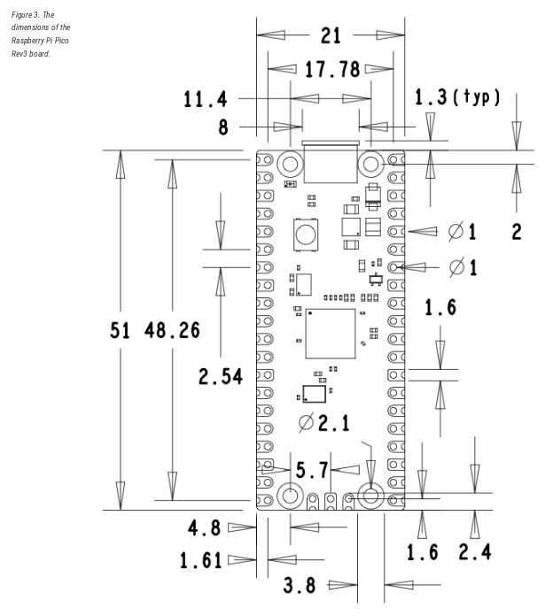
Mechanical Specifications
The Raspberry Pi Pico is a single sided 51x21mm 1mm thick PCB with a micro-USB port overhanging the top edge and dual castellated/through-hole pins around the remaining edges. Pico is designed to be usable as a surface mount module as well as being in Dual Inline Package (DIP) type format, with the 40 main user pins on a 2.54mm (0.1″) pitch grid with 1mm holes and hence compatible with veroboard and breadboard. Pico also has 4x 2.1mm (+/- 0.05mm) drilled mounting holes to provide for mechanical fixing, see Figure 3.
Mechanical specifications for the Raspberry Pi Pico
I hope that this is enough details to get all of you interested and eager for more details… In the next part of this series, I will focus on getting started with this new board, as well as do the official unboxing… Please stay tuned for more details…