Multiple I2C Devices on the same Bus, I2C Part 3

Today I will continue my series on I2C by showing you how to use multiple devices on the I2C bus. This will be an extremely short post, as it builds on skills that we have already covered.

I will connect the following

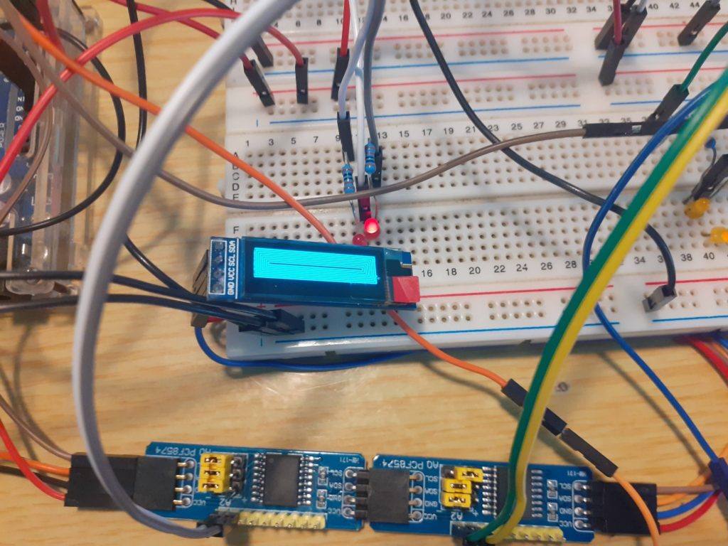
1 x 16×2 I2C LCD Screen address 0x27
1x 128×32 I2C OLED Display address 0x3C
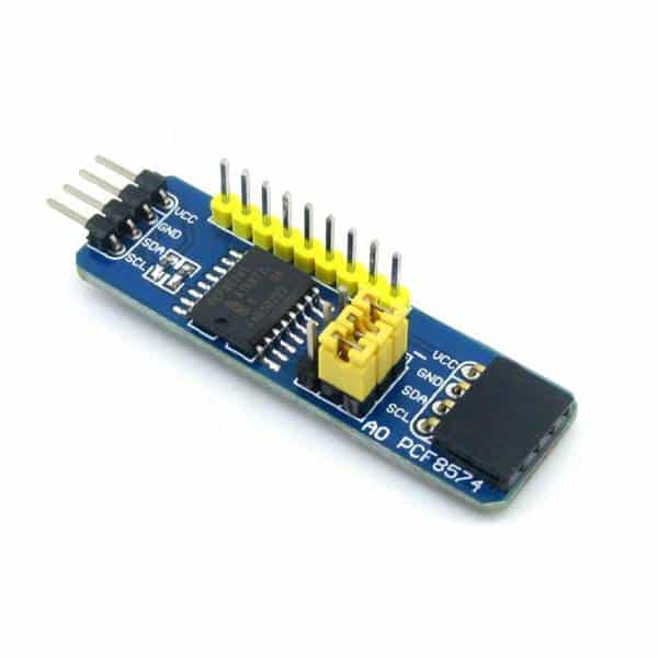
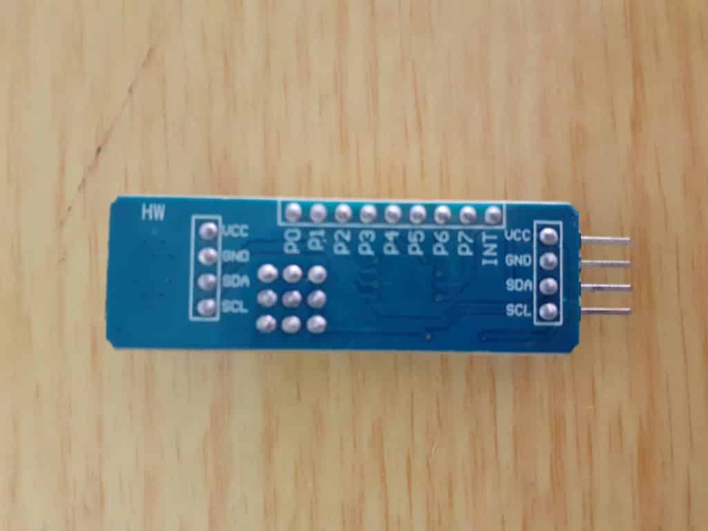
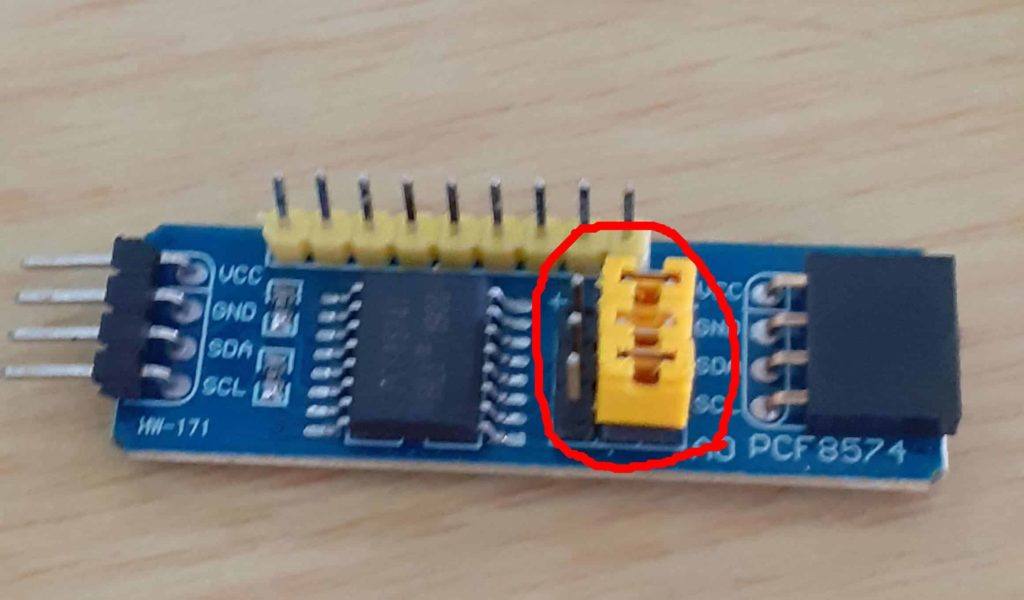
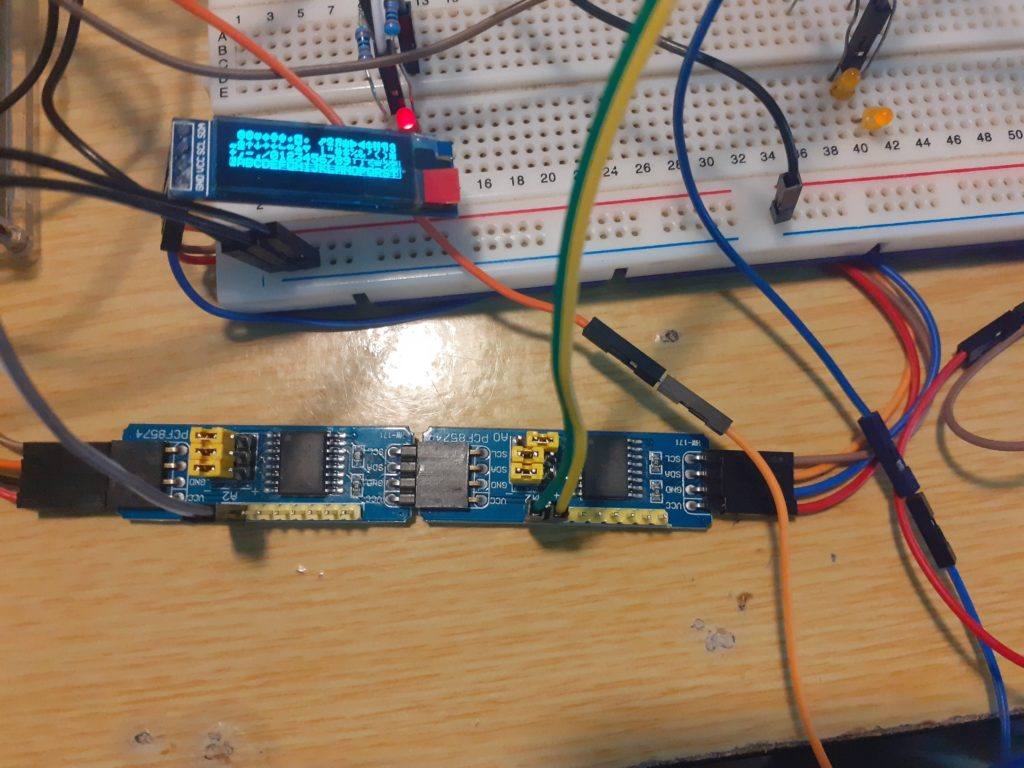
2x PCF8574 I2C Io Extenders address 0x20 and 0x21

All of these devices will be controlled from Arduino Uno, using the following libraries


LiquidCrystal_I2C.h to control the LCD screen,
Wire.h and PCF8574.h to control the I2C IO extenders and
Adafruit_GFX, Adafruit_SSD1306.h and SPI.h to control the SSD1306 128×32 OLED display.

With DuPont wires and breadboards being the reliable things they are, I decided that, after initial testing, I will not show you how to do button inputs on the PCF8574 at this stage. The amount of stray capacitance floating around on the breadboards, and small momentary push-button switches, made for a very impressive but unreliable mess of wires, with no real learning value to it 😉 Maybe some more on that later when I do a decent real-world example using these technologies 🙂

As the total distance between the devices is relatively short, it was not necessary to use pull-up resistors on the I2C bus in my setup. I suspect that that is due to the fact that they may already be included on some of my devices.

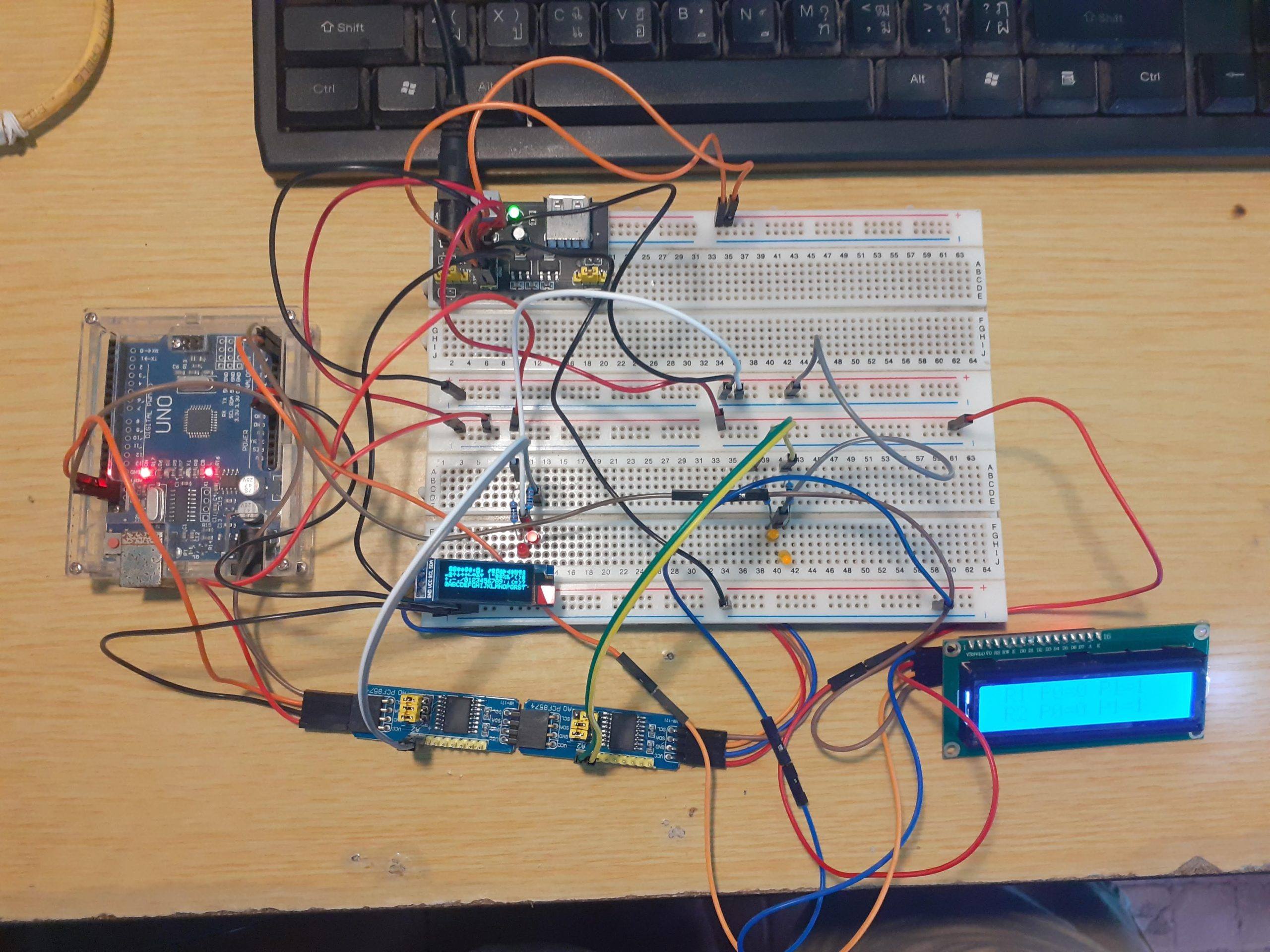
The circuit is quite straight forward.

  1. Connect all SDA pins on the I2C devices together serially, and connect that to the Arduino SDA pin ( That is usually A4)
  2. Connect all SCL pins on the I2C devices together serially, and connect that to the Arduino SCL pin ( That is usually A5)

    A note: On my Uno clone, there is an additional I2C breakout at the top of the device, near the USB adapter. I chose to use that as well as A4 and A5, as the bus hung itself up when connected to the breadboard. Your mileage may vary on this one 🙂
  3. Connect all 5v (Vcc) lines to 5v on the Arduino, and all Ground (GND) lines to GND on the Arduino.
  4. Now connect 4 LEDs, through a suitable resistor ( 640 ohms up to 1k ohm ) to pin P0 and P1 on both of the PCF8574 IO extenders. Also, connect the other leg of the LED to ground.
  5. I have powered my Uno from an external 5v power supply, as I did not want to pull too much current from the regulator on the actual Uno clone.

That should complete your hardware setup. Double check all your connections, and then load the i2c scanner sketch in the Arduino IDE, you may find it under the examples for the Wire.h library.

Power up the circuit, and upload the sketch to the Uno. Open the Serial Monitor.

You should see 4 I2C devices being detected. Note their addresses. If you dont see 4 devices, check your wiring and addresses. You may have a device with a conflicting address or a bad connection. If you used the breadboard to connect the bus, chances are very good that you will not see all the devices.

Good, if all of that is working, copy paste the following code into a new Arduino IDE window.
I will explain the code in the section below:

/*
  Multiple devices on the I2C bus
  Maker and Iot Ideas, MakerIoT2020
*/
// Include the libraries that we will need
#include <SPI.h> // needed for OLED display. 
#include <PCF8574.h> // PCF8574
#include <Wire.h> // Generic I2C library
#include <Adafruit_GFX.h> // for OLED display
#include <Adafruit_SSD1306.h> // for OLED display
#include <LiquidCrystal_I2C.h> // For I2C LCD display

// we need to define the size of the OLED screen

#define OLED_WIDTH 128
#define OLED_HEIGHT 32

// mine does not have an onboard reset pin. If yours do, specify the 
// pin that it is connected to on the Arduino here. To use the 
// Arduino reset pin, specify -1 as below

#define OLED_RESET -1

// Define the OLED display, width,hight protocol and reset pin
Adafruit_SSD1306 oled(OLED_WIDTH,OLED_HEIGHT, &Wire, OLED_RESET);

// Define the I2C LCD screen address and pin configuration
LiquidCrystal_I2C lcd(0x27,2,1,0,4,5,6,7,3,POSITIVE);

// Define the PCF8574 devices ( you can have up to 8 on a bus )
// but in this case, my LCD uses address 0x27, so I will have a 
// conflicting address if I were to use 8 of them together with the
// LCD

PCF8574 Remote_1(0x20); 
PCF8574 Remote_2(0x21);

// Note the I2C addresses. You can obtain them from the i2c_scanner

void setup() {
  // serial debugging if needed
  Serial.begin(115200);
  // Start OLED Display Init

  if (!oled.begin(SSD1306_SWITCHCAPVCC,0x3C)) { // Init the OLED 
    Serial.println(F("OLED INIT FAILED"));
    for(;;); // Dont proceed ... loop forever
  }
  oled.display();
  delay(2000); // This delay is required to give display time to 
  // initialise properly
  oled.clearDisplay();
  oled.setTextSize(0);
  oled.setTextColor(SSD1306_WHITE);
  oled.setCursor(0,0);
  oled.println("TEST SCREEN");
  oled.display();
  delay(2000);
  oled.clearDisplay();
  oled.setCursor(1,0);
  oled.println("OLED SCREEN ON");
  oled.display();

  // Start the LCD

  lcd.begin(16,2);
  
  // Set the initial state of the pins on the PCF8574 devices
  // I found that the PCF8574 library sometimes does funny things
  // This is also an example of how to use native i2c to set the 
  // status of the pins
  
  Wire.begin();
  Wire.beginTransmission(0x20); // device 1
  Wire.write(0x00); // all ports off
  Wire.endTransmission();
  Wire.begin();
  Wire.beginTransmission(0x21); // device 2
  Wire.write(0x00); // all ports off
  Wire.endTransmission();
  // Set pinModes for PCF8574 devices
  // Note that there are two of them

  Remote_1.pinMode(P0,OUTPUT);
  Remote_1.pinMode(P1,OUTPUT);
  Remote_2.pinMode(P0,OUTPUT);
  Remote_2.pinMode(P1,OUTPUT);
  
  // Start both IO extenders

  Remote_1.begin();
  Remote_2.begin();

  // and set ports to low on both
  // you may find that if you ommit this step, they come up in an
  // unstable state.

  Remote_1.digitalWrite(P0,LOW);
  Remote_1.digitalWrite(P1,LOW);
  Remote_2.digitalWrite(P0,LOW);
  Remote_2.digitalWrite(P1,LOW);
  
}

void loop() {
  // Draw a character map on the OLED display.
  // This function is borrowed from the Adafruit library

  testdrawchar();

  // Write to the IO extenders

  Remote_1.digitalWrite(P0,HIGH);
  Remote_1.digitalWrite(P1,LOW);
  Remote_2.digitalWrite(P0,HIGH);
  Remote_2.digitalWrite(P1,LOW);
  
  // Display their status on the LCD
  lcd.setCursor(0,0);
  lcd.print(" R1 P0=1 P1=0");
  lcd.setCursor(0,1);
  lcd.print(" R2 P0=1 P1=0");
  delay(500);

  // Change status
  Remote_1.digitalWrite(P1,HIGH);
  Remote_1.digitalWrite(P0,LOW);
  Remote_2.digitalWrite(P1,HIGH);
  Remote_2.digitalWrite(P0,LOW);

  // Update LCD
  lcd.setCursor(0,0);
  lcd.print(" R1 P0=0 P1=1");
  lcd.setCursor(0,1);
  lcd.print(" R2 P0=0 P1=1");
  delay(500);
  // Do some graphics on the OLED display
  // Function borrowed from Adafruit
  testdrawrect();
  oled.clearDisplay();
  delay(500);
  // repeat indefinitely

}

void testdrawrect(void) {
  oled.clearDisplay();

  for(int16_t i=0; i<oled.height()/2; i+=2) {
    oled.drawRect(i, i, oled.width()-2*i, oled.height()-2*i, SSD1306_WHITE);
    oled.display(); // Update screen with each newly-drawn rectangle
    delay(1);
  }

  delay(500);
}

void testdrawchar(void) {
  oled.clearDisplay();

  oled.setTextSize(1);      // Normal 1:1 pixel scale
  oled.setTextColor(SSD1306_WHITE); // Draw white text
  oled.setCursor(0, 0);     // Start at top-left corner
  oled.cp437(true);         // Use full 256 char 'Code Page 437' font

  // Not all the characters will fit on the display. This is normal.
  // Library will draw what it can and the rest will be clipped.
  for(int16_t i=0; i<256; i++) {
    if(i == '\n') oled.write(' ');
    else          oled.write(i);
  }

  oled.display();
  delay(500);
}

This concludes a quick and dirty show and tell… I hope that it will stimulate questions and ideas for a lot of people.

Thank you

Extending Arduino/Esp32/STM32 GPIO Pins – PART 2

In the first part of this series, I showed you how to extend the available output pins on your microprocessor by using a SIPO (Serial In, Parallel Out) Shift Register. These work great to extend your outputs, but they do tend to involve a bit of extra work and organisation in your code. They are also a bit slower than the normal GPIO pins, because data has to be serially shifted into them, and then latched out onto the parallel port.

I have also mentioned that there are I2C devices available that can make this much easier… In today’s article, I will show you how to use one of these I2C devices, the PCF8574.

These little modules have some quite impressive features, for one, allowing you to cascade up to 8 of them together, giving you a quite impressive 64 GPIO ports ! I am also happy to tell you, that if you can find the PCF8574A variant, as well, you can increase the total amount of ports to 128! ( If you chain 8x PCF8574 as well as 8x PCF8574A together) This is possible because the I2C addresses of the two series of chips are different. Thus allowing us to add a total of 16 of them to the I2C bus.

It must however be said that you should calculate your bus resistance very carefully if you plan on doing that. For most of us, I do not believe we will need that much GPIO on a single microprocessor!

Enough introduction, let us start by looking closely at the chip, as well as the modules that you can purchase for around 1 USD each…

A word of caution, there is also another version of these available, which is specifically designed to be used with LCD screens. You should thus be careful when you buy a premade module, that you choose the io-extender version, and not the LCD controller version.

PCF8574 I2C IO Extender module – Front View
PCF8574 I2C IO Extender – Back View

As we can see, the GPIO ports are clearly labeled, from P0 to P7, with the INT (Interrupt Pin) on the very right.

As I have said before, you can cascade up to 8 of these onto the I2C bus. This is done by setting the I2C address of the module. This is done by setting the jumpers as seen in the picture below.

Address Jumpers on the PCF8574 I2C IO Extender Module

The Address can be set by using the following table to lookup the address and set the jumpers accordingly.

A2A1A0I2C Device Address
0000x20
0010x21
0100x22
0110x23
1000x24
1010x25
1100x26
1110x27
Available I2C Addresses for PCF8574 selected by setting the jumpers

Connecting the device is very easy. You only have to supply 5v and Ground, as well as connect it to the SCL and SDA Pins on your microprocessor. For Arduino Uno / Nano that is A4 (SDA) and A5 (SCL)

As far as the coding is concerned, you have two options. You can either use the built-in Wire library, or you can download a special library. Both works equally well, but I do believe that the built-in Wire library might be a little bit faster.

Another point to make is that there are a lot of “fake” modules on the market these days. These modules work, but some of them have extremely weak current sourcing abilities. ( I recently bought a pair online, and they are unable to properly light an LED even without a current limiting resistor. I fixed that issue by driving the LED through a small BJT transistor, like the 2n2222a.

You should also take note that the ports will start up in a weak HIGH state when the module is powered up. This should be taken into consideration when designing your circuit to drive external devices through the outputs. In other words, you should take precautions to prevent the devices from switching on before the microprocessor takes control of the module.

Let us start to look at the coding that you will need to do to use this device.
I will start with the built-in wire Library that is included with the Arduino IDE.

#include <Wire.h> // Wire.h provide access to I2C functions

void setup()
{
Wire.begin(); // Start I2C
}

void loop()
{

Wire.beginTransmission(0x20); // Our device is on Address 0x20
Wire.write(0x0F); // This is equal to 0b00001111, meaning it will switch ports P0 to P3 High
Wire.endTransmission();
delay(1000);
Wire.beginTransmission(0x20);
Wire.write(0xF0); // This is equal to 0b11110000, meaning it will switch ports P4 to P7 High
Wire.endTransmission();
delay(1000);
}

The code above will alternate between switching 4 ports high and low every one second.
You can observe this by connecting 8 LEDs through 330ohm resistors to ports P0 through P7


Reading the status of a port (meaning that you configured it as an input) can be done using the following code

#include<Wire.h>

void setup()
{
  Serial.begin(9600);
  Wire.begin();
  Wire.beginTransmission(0x20);
  Wire.write(0x00);  //LED1 is OFF
  Wire.endTransmission();
}

void loop()
{
  Wire.requestFrom(0x20, 4); // Read the state of P4
  byte x = Wire.read();
  if (bitRead(x, 4) == LOW)
  {
    Wire.beginTransmission(0x20);
    Wire.write(0x01);  //LED1 is ON
    Wire.endTransmission();
  }
  else
  {
    Wire.beginTransmission(0x20);
    Wire.write(0x00);  //LED1 is OFF
    Wire.endTransmission();
  }
  delay(1000);
}

This code assumes that you have connected a LED throught a resistor to P0, and that you have connected a pullup resistor of 10k to P4, with a pushbutton to GROUND.

The LED should switch on when you press the switch, and go off again once you release it.

If you want to use the special library, you can download it below:

Install this into your Arduino Libraries, and use the following code:

include “Arduino.h”

include “PCF8574.h

// Set i2c address
PCF8574 pcf8574(0x20);

void setup()
{
Serial.begin(115200);

// Set pinMode to OUTPUT

pcf8574.pinMode(P0, OUTPUT);

pcf8574.begin();

}

void loop()
{
pcf8574.digitalWrite(P0, HIGH);
delay(1000);
pcf8574.digitalWrite(P0, LOW);
delay(1000);
}

Reading the status of an Input can be done like this:

include “Arduino.h”

include “PCF8574.h”

// Set i2c address
PCF8574 pcf8574(0x20);

void setup()
{
Serial.begin(115200);

pcf8574.pinMode(P0, OUTPUT);
pcf8574.pinMode(P1, INPUT);
pcf8574.begin();

}

void loop()
{
uint8_t val = pcf8574.digitalRead(P1);
if (val==HIGH) Serial.println(“KEY PRESSED”);
delay(50);

}

There are also excellent examples included with the library. These include using the interrupt pin.

I hope that this will be useful to somebody.

Extending the Inputs and Outputs of your Arduino/ESP32/STM32

There will come a time that you will run out of available input or output pins on your Arduino/ESP32 or STM32 device. Today, I will show you one way to work around this problem and how to add additional input and/or outputs to your device.

There are many ways to do this, the easiest of them being adding some sort of i2c
chip (the Waveshare PCF8574 IO Expansion Board is a good example).

This particular device can be cascaded to provide up to 64 IO ports on the i2c bus.

At Maker and IoT Ideas, we would however like to show you electronics that you can build yourself, or stuff that have not already been made up into some kind of commercial project.

So, keeping this DIY attitude going, I will teach you how to use a shift register today.

Before we do that, we have to look at what a shift register is, and how they work…

A shift register, at its basic level, is actually just a series of D Type Flip-Flops.

D Type Flip Flop

These flip flops are connected together to give this

Parallel in, Serial out Shift Register

There are three basic types of Shift Register
– Serial In, Serial Out (SISO)
– Serial In, Parallel Out (SIPO) and
– Parallel In, Serial Out (PISO)

We can see that they these type of shift registers are mainly used to convert between an serial and parallel data interface.

Serial In, Serial Out ( SISO)

This is the easiest configuration for a shift register. It is basically just a row of flip flops, with the output of the first, connected to the input of the next… and so on. This type of shift register is mainly used to introduce a delay into the data stream. This means that for a 8 bit SISO Shift register, the first data will only appear at the output after 8 clock cycles !

Serial In, Parallel Out (SIPO)

This kind of Shift Register has the same configuration as the SISO type, but it differs in that there is output after every flip-flop. That makes this type of shift register a good choice to use to extend the outputs on a microcontroller like Arduino or ESP32. The downside of using a shift register as a parallel output device is that the outputs will be slightly slower than if you used the native outputs on the microcontroller.

Parallel In, Serial Out (PISO)

A Parallel In, Serial out shift register can be used to read inputs from buttons or other digital devices. These inputs are then serially shifted into a serial pin on the microcontroller to be processed. It is also slightly slower than if you used the native inputs on the microcontroller.

Universal Shift register

You are also able to use a universal shift register. These chips can be used as both inputs and outputs. They are however only available in a 4 bit configuration.

The Chips (IC’s)

TYPELOGICCHIP NUMBERBITS
SISO / SIPOTTL74HC5958 bit
SIPOTTL74LS1648 bit
PISOTTL74HC1668 bit
UNIVERSALTTL74LS1944 bit
UNIVERSALTTL74LS1954 bit
UNIVERSALCMOSCD40354 bit
Some common Shift Register Chips

Example using Arduino with 74HC595n SIPO Shift Register

We will look at an example to connect the 74HC5959N to Arduino to drive eight (8) LEDs.
This example can be adapted to drive other loads as well by using a small BJT transistor and current limiting resistor instead of the LED

74hc595n Pin NumberDescription and Connection
Q0…Q7 (15,1,2,3,4,5,6,7)Parallel outputs of the shift register to write up to 8 signals with only 3 pins on your Arduino or ESP32 microcontroller
GND (8)Connect to the ground on the microcontroller
VCC (16)Connect to 3.3V or 5V on the microcontroller
DS (14)Serial data input has to be connected to the microcontroller (in this example D4)
OE (13)Output enable input do we not need and connected to ground
STCP (Latch) (12)Storage register clock input has to be connected to the microcontroller (in this example D5)
SHCP (11)Shift register clock input has to be connected to the microcontroller (in this example D6)
MR (10)Master reset connected to VCC because is active with LOW and we do not want to reset the register
Q7S (9)Serial data output not needed and therefore not connected
Connections for 74HC595n to Arduino

The operation of the 74hc595n SIPO Shift Register can easily be explained in three steps:

  1. The latch (STCP pin) is pulled LOW because the data is only stored in the register on a LOW to HIGH transition of this pin.
  2. Data is shifted out to the register with the data pin (DS) and with a LOW to HIGH transition of the clock signal (SHCP).
  3. The latch (STCP pin) is pulled HIGH to save the data in the register.

Make the following connections to your Arduino and Breadboard ( we will use Arduino Nano today, but you can use the same pins and code for Arduino Uno )

Breadboard Layout for 74HC595 Shift Register as Output Extender with Arduino Nano
Schematic Diagram for using 74HC595 Shift Register as Output Extender with Arduino Nano

Double-check all your connections, and then you can start the coding. The code will be much easier than you may think, as there is already a builtin function in the Arduino C language that we will use to shift the data out to the register.

// Define the Control Pins for the register
int latch-Pin = 5;
int clock-Pin = 7;
int data-Pin = 6;

void setup()
{
pinMode(latch-Pin, OUTPUT);
pinMode(data-Pin, OUTPUT);
pinMode(clock-Pin, OUTPUT);

Serial.begin(9600);
}

void loop()
{
byte leds = 0;
updateShiftRegister();
delay(1000);
for (int i = 0; i < 8; i++)
{
bitSet(leds, i);
updateShiftRegister();
for (int i = 7; i >= 0; i–)
{
bool b = bitRead(leds, i);
Serial.print(b);
}
delay(1000);
Serial.println(” “);
}
}

void updateShiftRegister()
{
digitalWrite(latch-Pin, LOW);
shiftOut(data-Pin, clock-Pin, LSBFIRST, less);
digitalWrite(latch-Pin, HIGH);
}

In this example, we output a HIGH to each led in turn, shifting from 0 to 7.

I hope that this will make sense to everybody, and be useful.
Questions and comments are welcome. Next time, we will look as using a PISO Shift register to extend the inputs on you Arduino/ESP32/STM32

Thank you.