Today I will continue my series on I2C by showing you how to use multiple devices on the I2C bus. This will be an extremely short post, as it builds on skills that we have already covered.
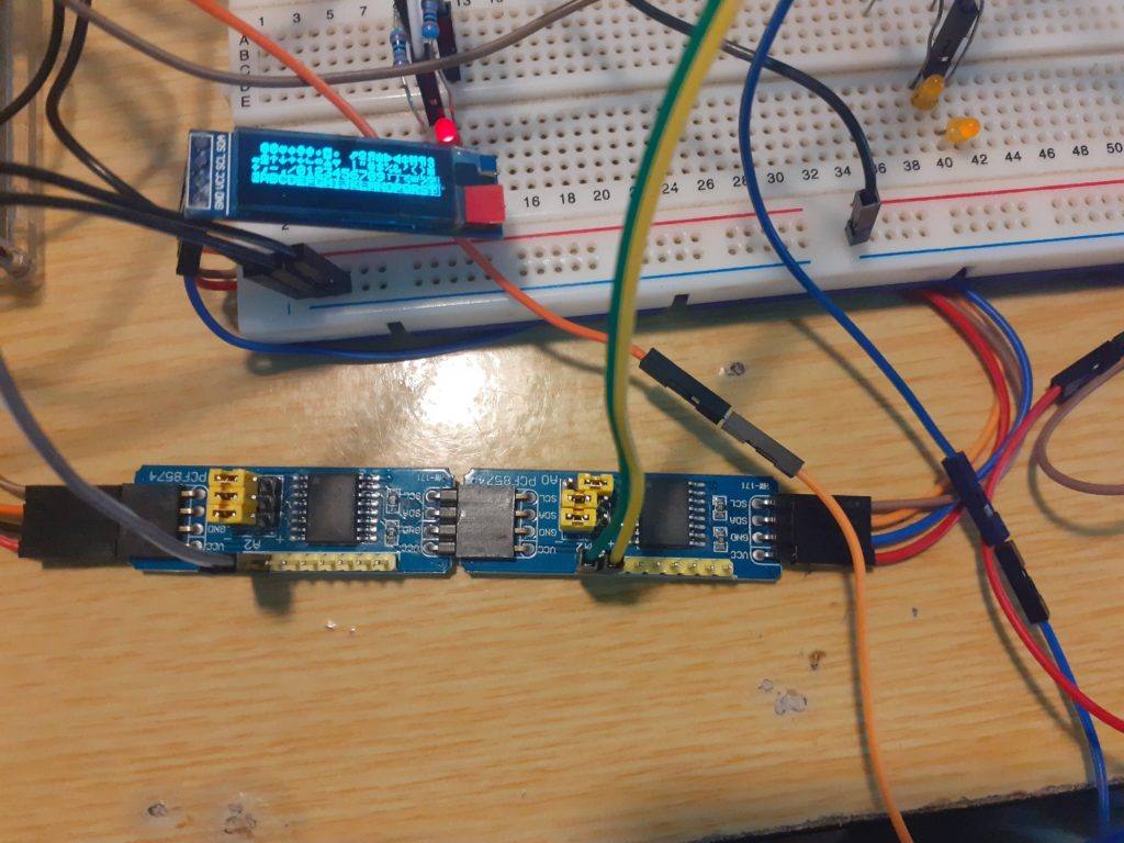
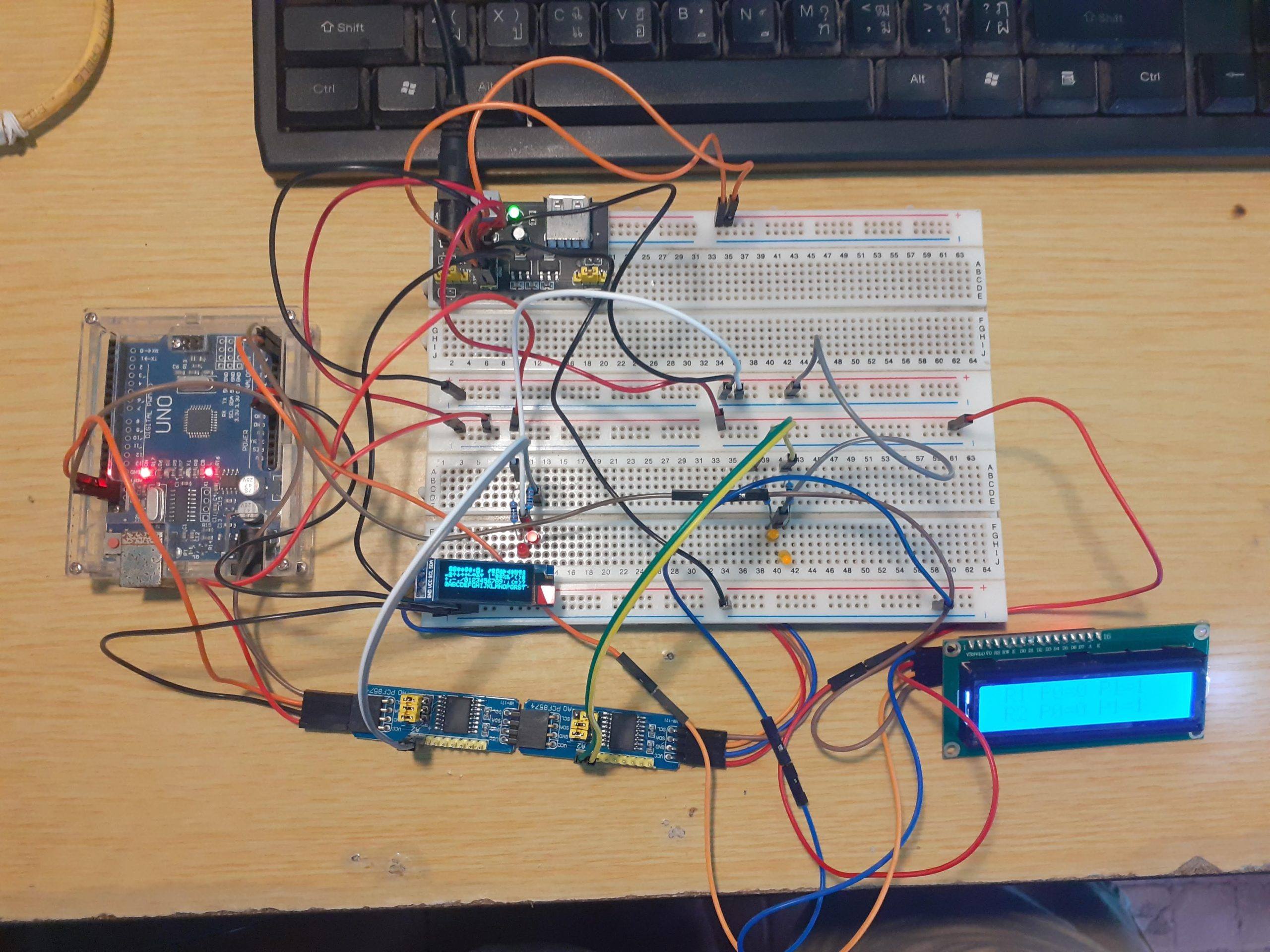
I will connect the following
1 x 16×2 I2C LCD Screen address 0x27
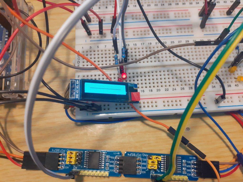
1x 128×32 I2C OLED Display address 0x3C
2x PCF8574 I2C Io Extenders address 0x20 and 0x21
All of these devices will be controlled from Arduino Uno, using the following libraries
LiquidCrystal_I2C.h to control the LCD screen,
Wire.h and PCF8574.h to control the I2C IO extenders and
Adafruit_GFX, Adafruit_SSD1306.h and SPI.h to control the SSD1306 128×32 OLED display.
With DuPont wires and breadboards being the reliable things they are, I decided that, after initial testing, I will not show you how to do button inputs on the PCF8574 at this stage. The amount of stray capacitance floating around on the breadboards, and small momentary push-button switches, made for a very impressive but unreliable mess of wires, with no real learning value to it 😉 Maybe some more on that later when I do a decent real-world example using these technologies 🙂
As the total distance between the devices is relatively short, it was not necessary to use pull-up resistors on the I2C bus in my setup. I suspect that that is due to the fact that they may already be included on some of my devices.
The circuit is quite straight forward.

- Connect all SDA pins on the I2C devices together serially, and connect that to the Arduino SDA pin ( That is usually A4)
- Connect all SCL pins on the I2C devices together serially, and connect that to the Arduino SCL pin ( That is usually A5)
A note: On my Uno clone, there is an additional I2C breakout at the top of the device, near the USB adapter. I chose to use that as well as A4 and A5, as the bus hung itself up when connected to the breadboard. Your mileage may vary on this one 🙂 - Connect all 5v (Vcc) lines to 5v on the Arduino, and all Ground (GND) lines to GND on the Arduino.
- Now connect 4 LEDs, through a suitable resistor ( 640 ohms up to 1k ohm ) to pin P0 and P1 on both of the PCF8574 IO extenders. Also, connect the other leg of the LED to ground.
- I have powered my Uno from an external 5v power supply, as I did not want to pull too much current from the regulator on the actual Uno clone.
That should complete your hardware setup. Double check all your connections, and then load the i2c scanner sketch in the Arduino IDE, you may find it under the examples for the Wire.h library.
Power up the circuit, and upload the sketch to the Uno. Open the Serial Monitor.
You should see 4 I2C devices being detected. Note their addresses. If you dont see 4 devices, check your wiring and addresses. You may have a device with a conflicting address or a bad connection. If you used the breadboard to connect the bus, chances are very good that you will not see all the devices.

Good, if all of that is working, copy paste the following code into a new Arduino IDE window.
I will explain the code in the section below:
/*
  Multiple devices on the I2C bus
  Maker and Iot Ideas, MakerIoT2020
*/
// Include the libraries that we will need
#include <SPI.h> // needed for OLED display.
#include <PCF8574.h> // PCF8574
#include <Wire.h> // Generic I2C library
#include <Adafruit_GFX.h> // for OLED display
#include <Adafruit_SSD1306.h> // for OLED display
#include <LiquidCrystal_I2C.h> // For I2C LCD display

// we need to define the size of the OLED screen

#define OLED_WIDTH 128
#define OLED_HEIGHT 32

// mine does not have an onboard reset pin. If yours do, specify the
// pin that it is connected to on the Arduino here. To use the
// Arduino reset pin, specify -1 as below

#define OLED_RESET -1

// Define the OLED display, width,hight protocol and reset pin
Adafruit_SSD1306 oled(OLED_WIDTH,OLED_HEIGHT, &Wire, OLED_RESET);

// Define the I2C LCD screen address and pin configuration
LiquidCrystal_I2C lcd(0x27,2,1,0,4,5,6,7,3,POSITIVE);

// Define the PCF8574 devices ( you can have up to 8 on a bus )
// but in this case, my LCD uses address 0x27, so I will have a
// conflicting address if I were to use 8 of them together with the
// LCD

PCF8574 Remote_1(0x20);
PCF8574 Remote_2(0x21);

// Note the I2C addresses. You can obtain them from the i2c_scanner

void setup() {
  // serial debugging if needed
  Serial.begin(115200);
  // Start OLED Display Init

  if (!oled.begin(SSD1306_SWITCHCAPVCC,0x3C)) { // Init the OLED
    Serial.println(F("OLED INIT FAILED"));
    for(;;); // Dont proceed ... loop forever
  }
  oled.display();
  delay(2000); // This delay is required to give display time to
  // initialise properly
  oled.clearDisplay();
  oled.setTextSize(0);
  oled.setTextColor(SSD1306_WHITE);
  oled.setCursor(0,0);
  oled.println("TEST SCREEN");
  oled.display();
  delay(2000);
  oled.clearDisplay();
  oled.setCursor(1,0);
  oled.println("OLED SCREEN ON");
  oled.display();

  // Start the LCD

  lcd.begin(16,2);

  // Set the initial state of the pins on the PCF8574 devices
  // I found that the PCF8574 library sometimes does funny things
  // This is also an example of how to use native i2c to set the
  // status of the pins

  Wire.begin();
  Wire.beginTransmission(0x20); // device 1
  Wire.write(0x00); // all ports off
  Wire.endTransmission();
  Wire.begin();
  Wire.beginTransmission(0x21); // device 2
  Wire.write(0x00); // all ports off
  Wire.endTransmission();
  // Set pinModes for PCF8574 devices
  // Note that there are two of them

  Remote_1.pinMode(P0,OUTPUT);
  Remote_1.pinMode(P1,OUTPUT);
  Remote_2.pinMode(P0,OUTPUT);
  Remote_2.pinMode(P1,OUTPUT);

  // Start both IO extenders

  Remote_1.begin();
  Remote_2.begin();

  // and set ports to low on both
  // you may find that if you ommit this step, they come up in an
  // unstable state.

  Remote_1.digitalWrite(P0,LOW);
  Remote_1.digitalWrite(P1,LOW);
  Remote_2.digitalWrite(P0,LOW);
  Remote_2.digitalWrite(P1,LOW);

}

void loop() {
  // Draw a character map on the OLED display.
  // This function is borrowed from the Adafruit library

  testdrawchar();

  // Write to the IO extenders

  Remote_1.digitalWrite(P0,HIGH);
  Remote_1.digitalWrite(P1,LOW);
  Remote_2.digitalWrite(P0,HIGH);
  Remote_2.digitalWrite(P1,LOW);

  // Display their status on the LCD
  lcd.setCursor(0,0);
  lcd.print(" R1 P0=1 P1=0");
  lcd.setCursor(0,1);
  lcd.print(" R2 P0=1 P1=0");
  delay(500);

  // Change status
  Remote_1.digitalWrite(P1,HIGH);
  Remote_1.digitalWrite(P0,LOW);
  Remote_2.digitalWrite(P1,HIGH);
  Remote_2.digitalWrite(P0,LOW);

  // Update LCD
  lcd.setCursor(0,0);
  lcd.print(" R1 P0=0 P1=1");
  lcd.setCursor(0,1);
  lcd.print(" R2 P0=0 P1=1");
  delay(500);
  // Do some graphics on the OLED display
  // Function borrowed from Adafruit
  testdrawrect();
  oled.clearDisplay();
  delay(500);
  // repeat indefinitely

}

void testdrawrect(void) {
  oled.clearDisplay();

  for(int16_t i=0; i<oled.height()/2; i+=2) {
    oled.drawRect(i, i, oled.width()-2*i, oled.height()-2*i, SSD1306_WHITE);
    oled.display(); // Update screen with each newly-drawn rectangle
    delay(1);
  }

  delay(500);
}

void testdrawchar(void) {
  oled.clearDisplay();

  oled.setTextSize(1);      // Normal 1:1 pixel scale
  oled.setTextColor(SSD1306_WHITE); // Draw white text
  oled.setCursor(0, 0);     // Start at top-left corner
  oled.cp437(true);         // Use full 256 char 'Code Page 437' font

  // Not all the characters will fit on the display. This is normal.
  // Library will draw what it can and the rest will be clipped.
  for(int16_t i=0; i<256; i++) {
    if(i == '\n') oled.write(' ');
    else          oled.write(i);
  }

  oled.display();
  delay(500);
}
This concludes a quick and dirty show and tell… I hope that it will stimulate questions and ideas for a lot of people.
Thank you

