In part 1 of this article, I introduced my new I2C 8DI Optically Isolated Arduino Shield. Today, I will show you how the full design, as well as the circuit diagram.
This shield was designed to allow an input of between 3.0v and 32.0v to be applied to the various inputs. This will be completely galvanic isolated from the rest of the circuitry on the shield, and thus also from your Arduino, or other micro-controller if you choose to use another one 🙂 Yes, This is possible, as long as you power the shield with 3.0v to 5.0v. You will also have to connect your I2C bus to the SCL and SDA Lines marked on the shield.
Please note that, if you decide to do that, the other Arduino specific pins, as broken out on the shield headers, will have no connections to anything else. :), an obvious fact, but it should be stated, it seems 🙂
The Circuit Diagram
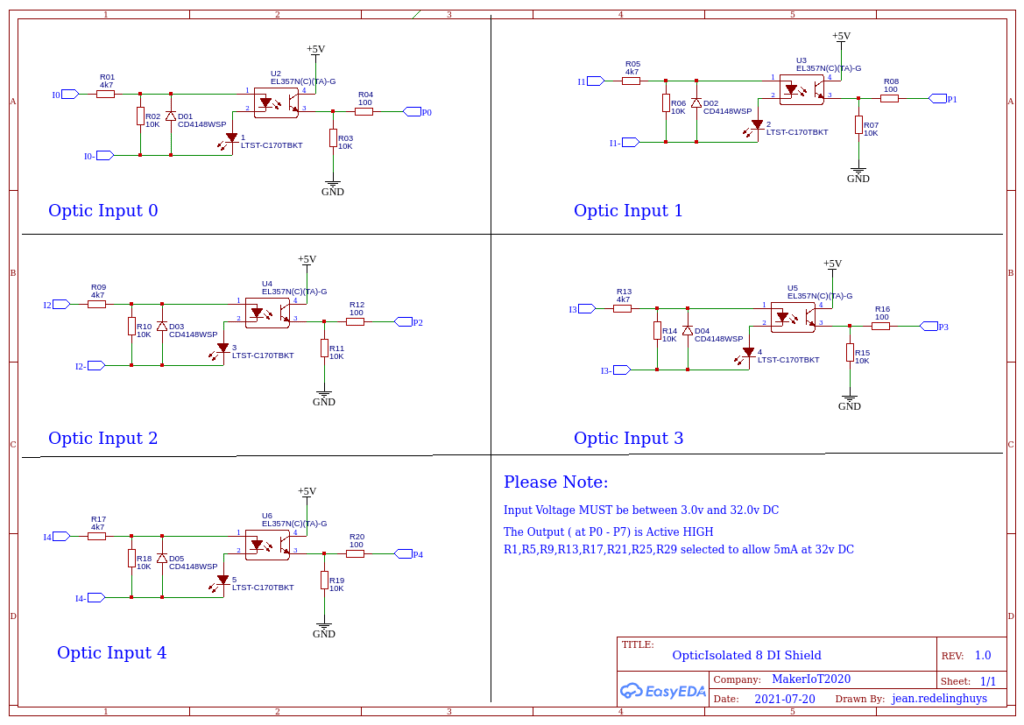
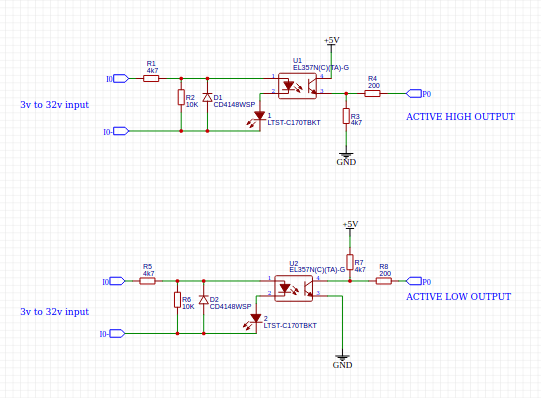
As you can see on page 1, each optically isolated input has a voltage divider resistor network in front of the Opto Coupler. This resistor network also limits the current that can be used by the infrared LED inside of the EL357N chip to 5mA at 32v DC. ( The chip can accept up to 50mA, but it should not be driven so hard 🙂 ) A diode provides reverse-polarity protection to each input as well.
Another voltage divider on the output side limits the current to the PCF8574 Chip. This can also only source or sink 25mA per IO.
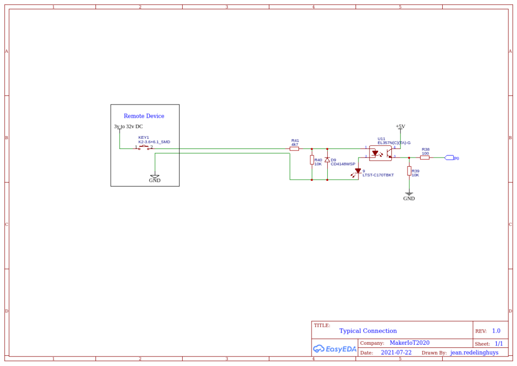
Note that there is NO common ground between the input and output sides of this circuit. That means that you have to provide another ground, usually from your external device… This ensures that galvanic isolation between the two circuits is maintained.
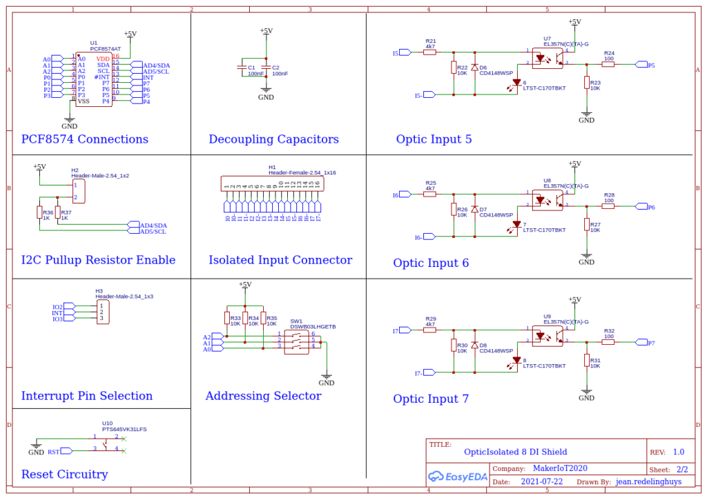
On page 2, we can see the various net connections to the connectors, PCF8574 chip, as well as various jumper headers, to select the interrupt pin [H3] ( For Arduino, D2 or D3, other micro-controllers: you are free to select any GPIO to connect to the D2 or D3 header pin ).
You can also select to enable or disable the pull-up resistors on the I2C bus, by shorting the jumper on [H2].
This is usually only needed on the first shield, or in other words, you need one pair of pullup resistors per i2c bus, not one pair per device!
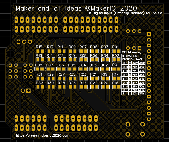
Device addressing is selected with SW1. 8 addresses are available but switching this switch as per the table on the back of the PCB. It is worth mentioning that depending on the version of the PCF8574 chip that is on the shield, there are 8 addresses available, with 0x20h to 0x27h being common on the PCF8574, and 0x38h to 0x3fh being used on the PCF8574A/T version.
Typical Connection
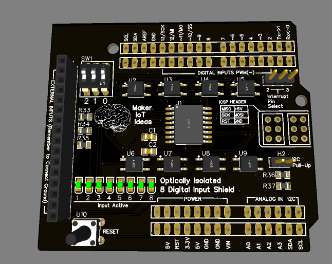
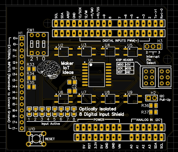
The PCB
The shield is built on a double-sided PCB or 71.12mm x 61.72mm. This is only slightly bigger than the standard Arduino Uno. All resistors, capacitors and LED’s are of 0805 sizes. ( smaller than that is a bit hard on my eyes, although it can be done, just takes longer 🙂 ). A ground plane is provided on both sides of the PCB.
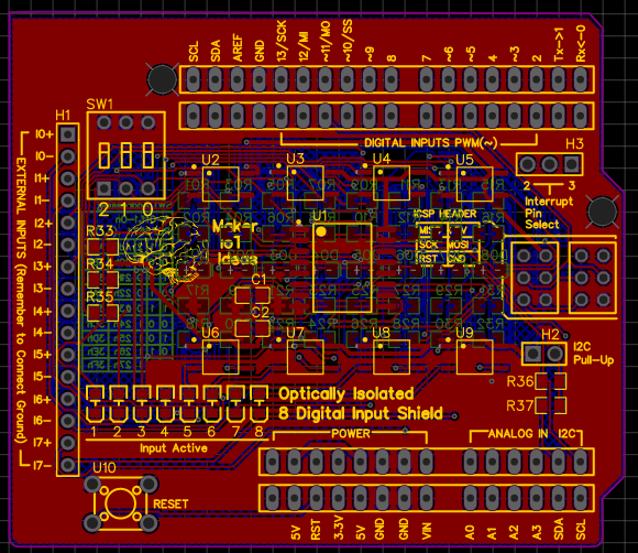
All Arduino pins are broken out on a double row of 2.54mm headers. This allows you to use either the outside row with stack-able male-female headers, like on most shields, or you can use dedicated male and female headers, in a zig-zag pattern to stack the shields.
I have done the same with the ICSP header, as on many other commercially available shields, there is only a single female 3×2 header on the bottom, making it quite annoying to use on another shield.
Manufacturing
This shield is currently being manufactured by PCBWay.

PCBWay provides a rapid and affordable PCB manufacturing service. They also provide PCB assembly, and even a 3D printing and CNC service. This can really help to bring new electronic prototypes to market quickly, as PCBWay can provide you with a complete turn-key solution to bring your product to market. The process to order a PCB is also completely automated, and you can easily do it online in a few minutes. Just upload your completed Gerber Files onto their system via their web interface, and you will get a quote in seconds. You can then pay and place your order immediately from the same page. They also have various shipping methods available, That really helps, as no one wants to pay for excessively expensive shipping, or be stuck having to use only one company.
The design files for this project will be made available as a project on the PCBWay website soon after the release of part 3, which will cover the assemble, testing and programming of the shield.