Why did I do this?
Of all the various development boards in my electronics lab, surely the most versatile, but most neglected must be the STM32 Blue Pill. Not that there is anything wrong with it, It is a very very nice board, but unfortunately, there are a few issues ( mostly personal ) that make it not jump out at me for use in a new project.
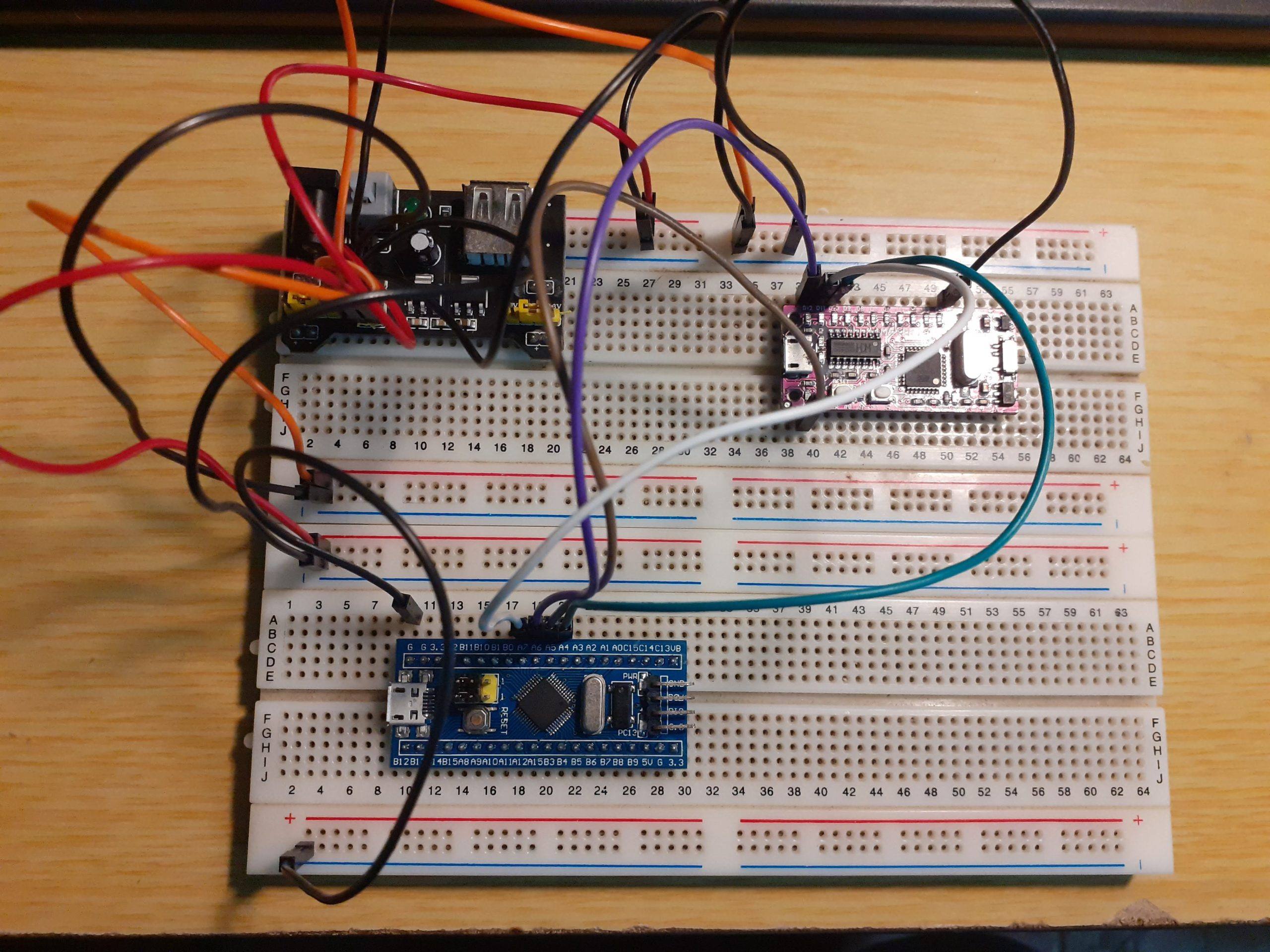
Of these, and quite similar to the Arduino Nano, and original Raspberry Pi Pico is the fact that it was designed to be mostly used on a breadboard, issues with using the USB port, wrong components installed at the factories, and needing magnification to read port numbers, made me decide to solve it in my own way.
It is also not possible to use it (the original Blue-Pill) with any of the ready-made shields for the Arduino Nano, due to different pin-outs etc. Thus requiring a mess of wires and more modules on a breadboard, or lying free on the bench, to add sensors and other devices to this particular development board…
It can be argued that its small size does make it attractive, with which I definitely do not disagree, but unlike the bigger STM32 development boards with a lot of included peripherals, or the Arduino Ecosystem, where it is possible to develop your hardware prototypes on an Arduino Uno, using various shields, and then move on to a custom PCB later, the blue pill’s development cycle seems to be very much tied to the use of a breadboard and/or modules connected with jumper wires etc…
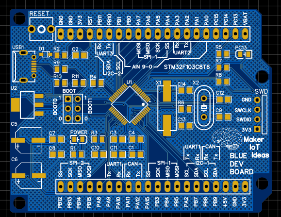
My idea was thus to take some inspiration from the bigger STM32 Nucleo and Discovery type platforms, add very detailed, and readable pin numbers, and peripheral descriptions, as well as lay a foundation onto which I can in future design stackable shields to expand the functionality of the device.
In order to make it easier for Makers and Hobby Electronics Enthusiasts, the new PCB was designed with 0805 SMD components. These are still quite easy to solder by hand, and usually do not require the use of any special equipment (That most beginners just starting out with the hobby won’t necessarily own or have access to by default). All of this was done with the hope that more people will start using this form factor, as well as to stimulate the development of shields and add-on cards to truly bring the blue pill to the same level regarding ease-of-use that the Arduino Ecosystem currently occupies.
What changes did I make?
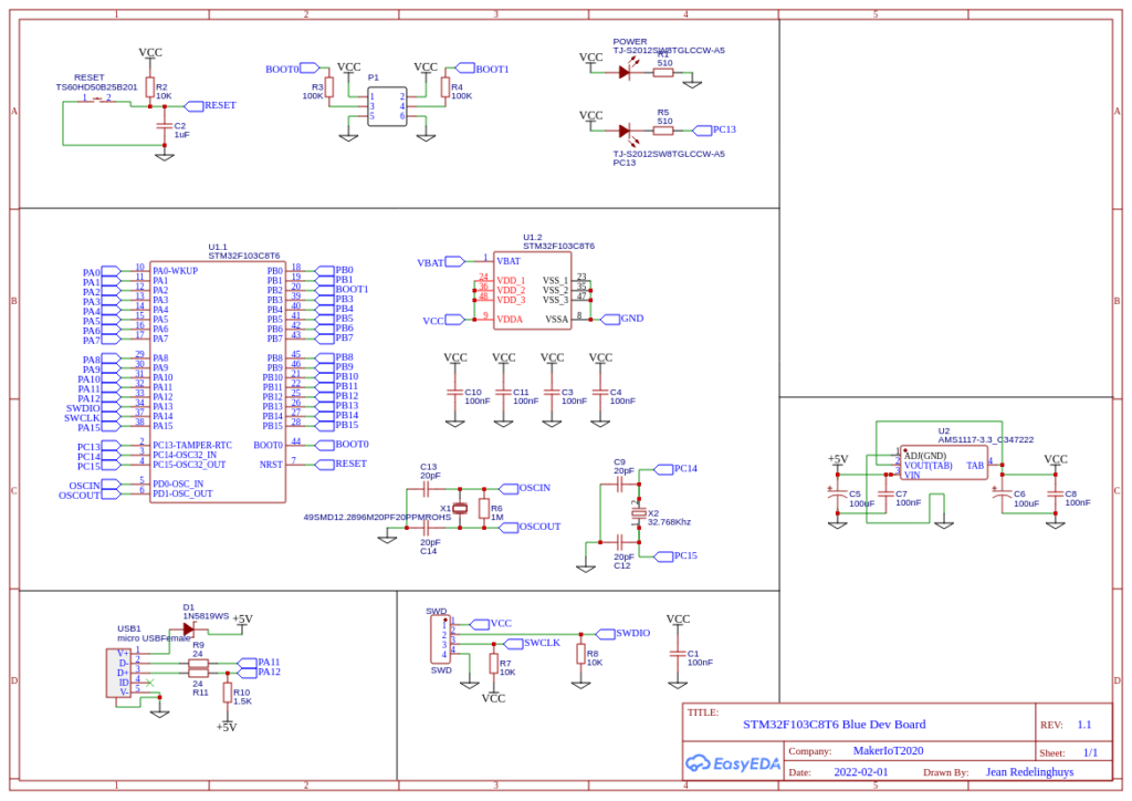
The schematic diagram was not changed at all. All ports and pin numbers are 100% compatible with the original Blue Pill. Components sizes were changed from 0402 to 0805. I also made sure that the USB port would be functional, and would not require any modifications to be performed to make it useable (unlike some of the blue pill PCB’s available in Asia, which ships with a wrong value resistor at R10.
The PCB form factor has been changed to be the same size as the Arduino Uno, but with two rows of 20-pin 2.54mm headers. A more powerful 3.3v LDO regulator and additional smoothing capacitors were added. The main changes are to the silkscreen, where the pin numbering was enlarged to be more easily readable, and detailed labelling of the various possible peripherals were added. The board is also a single layer PCB, whereas the original was a double layer PCB, due to its small size.
Where and when can you get one?
The PCB is currently in production at PCBWay. When I have completed all testing of the PCB, it will be available as a PCBWay shared project, which means that you can order your own, or freely download the Manufacturing files to produce your own if you so choose. You can also contact me directly.
I plan to have completed all testing and to make available the manufacturing files, by the end of February 2022. Please be patient.

This PCB was manufactured at PCBWAY. The Gerber files and BOM, as well as all the schematics, will soon be available as a shared project on their website. If you would like to have PCBWAY manufacture one of your own, designs, or even this particular PCB, you need to do the following…
1) Click on this link
2) Create an account if you have not already got one of your own.
If you use the link above, you will also instantly receive a $5USD coupon, which you can use on your first or any other order later. (Disclaimer: I will earn a small referral fee from PCBWay. This referral fee will not affect the cost of your order, nor will you pay any part thereof.)
3) Once you have gone to their website, and created an account, or login with your existing account,

4) Click on PCB Instant Quote

5) If you do not have any very special requirements for your PCB, click on Quick-order PCB
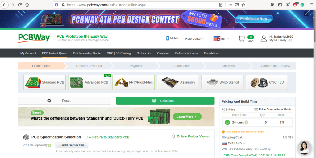
6) Click on Add Gerber File, and select your Gerber file(s) from your computer. Most of your PCB details will now be automatically selected, leaving you to only select the solder mask and silk-screen colour, as well as to remove the order number or not. You can of course fine-tune everything exactly as you want as well.


7) You can also select whether you want an SMD stencil, or have the board assembled after manufacturing. Please note that the assembly service, as well as the cost of your components, ARE NOT included in the initial quoted price. ( The quote will update depending on what options you select ).
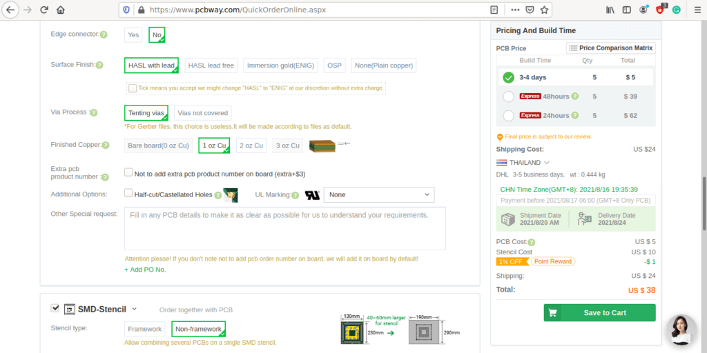

8) When you are happy with the options that you have selected, you can click on the Save to Cart Button. From here on, you can go to the top of the screen, click on Cart, make any payment(s) or use any coupons that you have in your account.
Then just sit back and wait for your new PCB to be delivered to your door via the shipping company that you have selected during checkout.