
Sometimes it is necessary to send data between two microprocessors.
The SPI bus is a very fast serial data-bus that is normally used to interface with various peripherals like OLED Screens, Radios and various sensors. In today’s very short post, I will show you how to interface the STM32F103C8T6 “Blue Pill” with an Arduino Nano to send bidirectional data via the SPI Interface between the two microprocessors. You will need the following to experiment with this by yourself.
1) An STM32F103C8T6 ” Blue Pill”
2) An Arduino Compatible or Original Uno or Nano
3) Two Breadboards
4) Some Linkup wires (at least 4 male-to-male DuPont wires)
Let us look at the pin configuration on the two boards
| PIN NAME | “Blue Pill” | Arduino Nano or Uno |
| MOSI | PA7 | D11 |
| MISO | PA6 | D12 |
| SCK | PA5 | D13 |
| SS | PA4 | D10 |

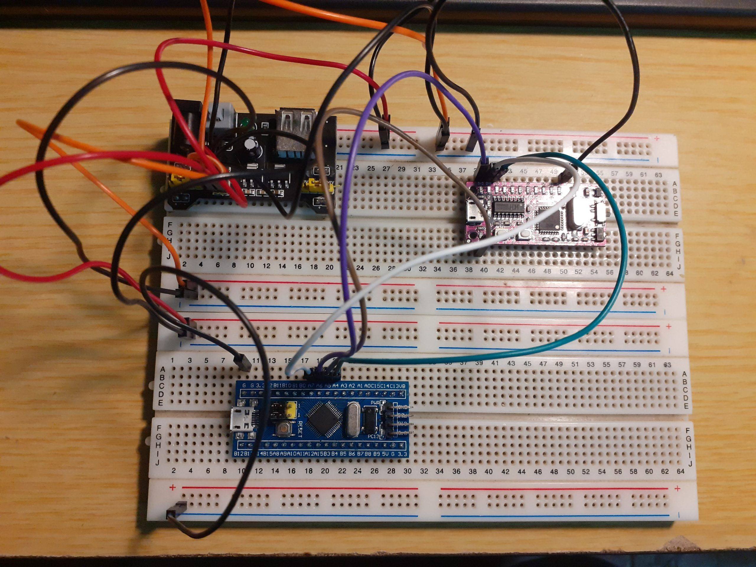
Connections for the “Blue Pill” are shown above

Connections for Maker NANO are shown above
You can now type in the code for the Master ( The Blue Pill ) into your Arduino IDE
#include<SPI.h>
// Define Constants and Variables
#define SS PA4
#define led PC13
unsigned char MasterSend;;
unsigned char MasterReceive;
void setup() {
pinMode(led,OUTPUT);
Serial.begin(115200);
// SPI Init
SPI.begin();
SPI.setClockDivider(SPI_CLOCK_DIV16);
digitalWrite(SS,HIGH); // set as master
MasterSend = 0xFF;
}
void loop() {
Serial.print(“Sent to Slave “);
Serial.print(” [0x”);
Serial.println(MasterSend,HEX);
MasterReceive = SPI.transfer(MasterSend);
Serial.print(“Received from Slave “);
Serial.print(” [0x”);
Serial.print(MasterReceive,HEX);
Serial.println(“]”);
digitalWrite(led,!digitalRead(led));
delay(200);
}
And in ANOTHER INSTANCE of the Arduino IDE, the code for the SLAVE (Maker NANO)
//SPI Slave Code for Arduino
//SPI Communication between STM32F103C8 & Arduino
#include<SPI.h>
volatile boolean received;
volatile unsigned char SlaveReceived;
volatile unsigned char SlaveSend;
void setup()
{
Serial.begin(115200);
pinMode(MISO,OUTPUT);
SPCR |= _BV(SPE);
received = false;
SPI.attachInterrupt();
SlaveSend = 0xAA;
}
ISR(SPI_STC_vect)
{
SlaveReceived = SPDR;
received = true;
}
void loop() {
Serial.print(“Received from Master”);
Serial.print(” [0x”);
Serial.print(SlaveReceived,HEX);
Serial.println(“] “);
SPDR = SlaveSend;
Serial.print(“Sent to Master”);
Serial.print(” [0x”);
Serial.print(SlaveSend,HEX);
Serial.println(“]”);
delay(200);
}
Upload the code to the boards, and open the serial monitors on both instances of the Arduino IDE.
Set the Baud Rate to 115200
You will see that the Master sends a byte to the Slave, and the Save replies with a byte of it’s own.
Master sends data to Slave, Receives Data Back

Slave received data from Master, and replies with data of its own

This sketch can now very easily be modified to send reading from sensors, or instructions to control other peripherals between the two microprocessors. It is limited only by your imagination, and your ability to code.
I hope you found this interesting and useful.