
Due to their high capacity and relatively low cost, LiPo cells are almost everywhere these days. This Low BOM cost 4-cell 18650 Charger module is my attempt to solve another issue.

The 18650 Lipo cell is quite common in my lab, and for an excellent reason, as mentioned above, they are cost-effective and also store quite a bit of energy. recharging them after use has however been quite a lengthy exercise in the past.
The usual process involved a few Lipo Charging modules, all connected via USB cables, charging one cell at a time. This not only takes up quite a bit of time and space but also occupies USB ports that could be used for other purposes.
Based on the ultra-cheap TP4056 chip, these single-cell charging modules cost peanuts, but with the required wiring and battery holders, as well as the cables to supply power, it does not really look very neat. I have thus been looking for a better solution for quite a while now, and had quite a few requirements for my “ideal” module.
The MCP73832 from MICROCHIP seemed like a good choice for a custom design, as it requires only 5 additional external components, which are only two resistors, two capacitors and an led. The chip is also extremely low-cost.

- High accuracy preset output voltage regulation (+/-0.75%)
- Output voltage options include 4.2V, 4.35V, 4.4V and 4.5V
- User-programmable charge current
- Open-drain status output
- On-chip thermal regulation
- Preconditioning and end-of-charge ratio options
- Under-voltage lockout
Includes integrated pass transistor, integrated current sensing, and reverse discharge protection in 5-pin SOT-23 and thermally-efficient 8-pin 2mm x 3mm DFN packages.

The Prototype Module

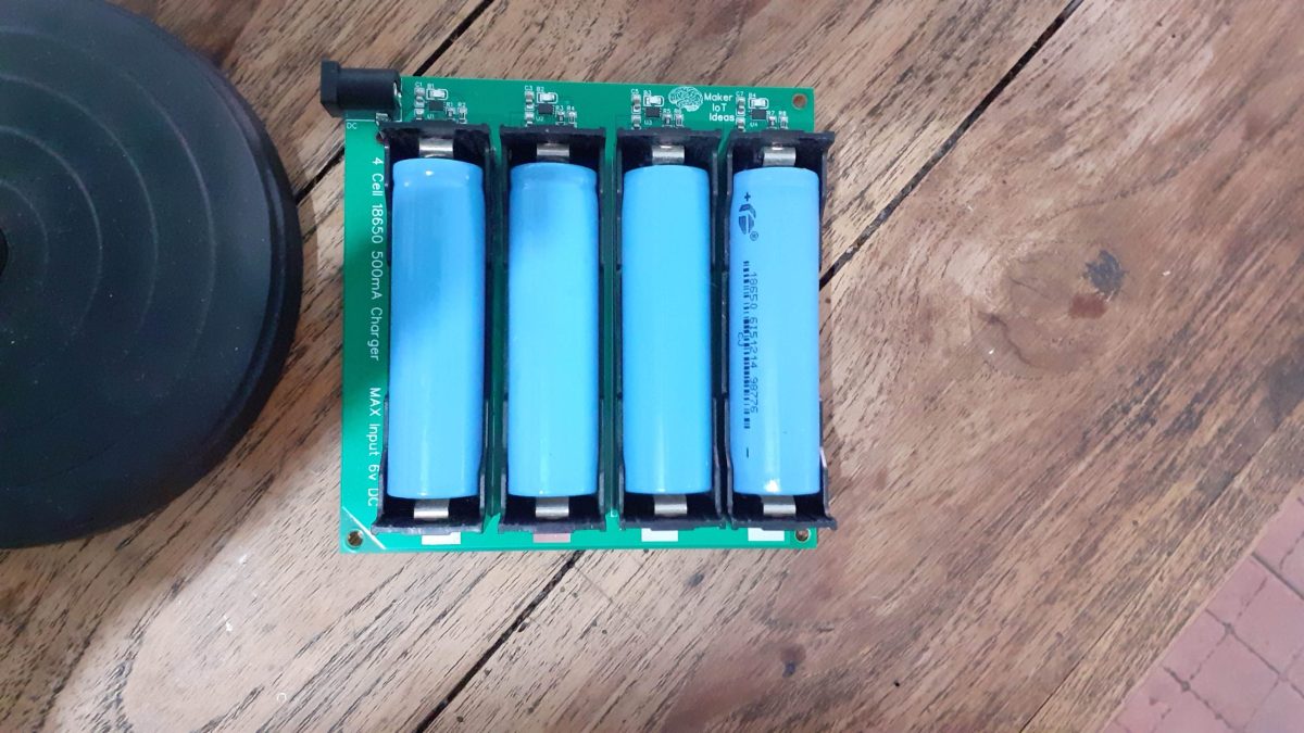
The design that I came up with, can charge 4-cell simultaneously. The maximum input voltage is limited to 6v DC.

Another interesting feature is the ability to use either through-hole battery holders or SMD ones. I did that because I have quite a few of the through-hole ones in stock, but as they were bought quite a while ago, the exact part number went on holiday. When having the module assembled in the factory,the SMD parts can be used, as there seems to be plenty in stock.
The Schematic

Because I enjoy a challenge, the design uses the smaller 3mm 2mm DFN8 package. Charging current is set with R9, which is 2k in this case, which will result in a charging current of the full 500mA. You can adjust it as per your requirements, to a value between 2k and 10k, as per the datasheet.
The full schematic is available here:
PCB Design

The PCB design was optimised to fit on a 10cm x 10cm board. Most of the board is made up of a solid copper pour to provide a good ground plane. Charging circuitry is placed as close together as possible, with a good connection of the thermal pad on the DFN8 package to the ground plane to help with thermal regulation. In this case, I have attempted to replicate the suggested reference design as closely as possible, while adapting it for use with the DFN8 package (Reference design uses the 5 lead SOT-23 package)

As seen in the close-up, components are placed as close as possible to the MCP73832, and via stitching are used to ensure a good connection to the ground, as well as allow the ground plane to serve as a heatsink.
Manufacturing
I choose PCBWay for my PCB manufacturing. Why? What makes them different from the rest?
PCBWay‘s business goal is to be the most professional PCB manufacturer for prototyping and low-volume production work in the world. With more than a decade in the business, they are committed to meeting the needs of their customers from different industries in terms of quality, delivery, cost-effectiveness and any other demanding requests. As one of the most experienced PCB manufacturers and SMT Assemblers in China, they pride themselves to be our (the Makers) best business partners, as well as good friends in every aspect of our PCB manufacturing needs. They strive to make our R&D work easy and hassle-free.
How do they do that?
PCBWay is NOT a broker. That means that they do all manufacturing and assembly themselves, cutting out all the middlemen, and saving us money.
PCBWay’s online quoting system gives a very detailed and accurate picture of all costs upfront, including components and assembly costs. This saves a lot of time and hassle.
PCBWay gives you one-on-one customer support, that answers you in 5 minutes ( from the Website chat ), or by email within a few hours ( from your personal account manager). Issues are really resolved very quickly, not that there are many anyway, but, as we are all human, it is nice to know that when a gremlin rears its head, you have someone to talk to that will do his/her best to resolve your issue as soon as possible.
Find out more here

Assembly
Assembly of this module definitely requires the use of a stencil. The DFN-8 package of the IC is only 3mm x 2mm, and there are 8 leads as well as a thermal pad crammed in there. A stencil will ensure that you add just the correct amount of solder paste to each pad.

As we can clearly see in this cropped picture of the stencil, those pads are SUPER tiny.
I chose to use the hotplate, as well as some hot air for the SMD component assembly. The battery holders and DC barrel-connector are all through-hole, and were thus assembled using a standard soldering iron, with slightly thicker solder, and a bit more heat than normal, as the pads are quite big, and the big copper pour really sucks the heat away from the joints.
Testing
Testing the module went really well. I used four 18650 cells that needed recharging, and they were very quickly ( in about 1 hour ) charged to 4.20 volt.
The Charge Indicator LED on each charging circuit works in reverse from what we would normally expect, with it lighting up while charging, and going out when done.
The current draw (measured on the bench power supply) verified that each cell was charging at the 500mA as designed. The current draw also reduced as each cell charging cycle completed and eventually went down to very close to zero (The Ampere meter on my bench supply can not measure very low current with a lof of accuracy -:) )
Measuring each cell that have completed its charging cycle with a standard multimeter confirmed that they were indeed at 4.20v, and that the charging circuitry was no longer feeding current to any of them.
Drawing current out of a single cell (I used a set of clips ) to power a dummy load, resulted in an automatic recharge cycle being initiated once the cell voltage dropped past the set charging threshold.
It is however VERY important to note that this module is by NO means a balanced cell charger. It is a 4-way single cell charger that charges 4 cells independently from each other, at the same time. It is thus completely possible as well as probable that the four cells will/may be at slightly different voltages at the end of each respective charging cycle.
Conclusion
This project is most definitely high on the list of my most needed items. Keeping a bunch of 18650 cells charged and correctly maintained can be quite a chore, and the way that I have done it in the past was definitively not ideal.
It has also cost me quite a few cells that died way before their time.
Using this module, the chore of charging these cells will be reduced by a lot, and hopefully, in the future, I will come up with a solution to augment this module so that I can have these cells on a semi-permanent charge, with monitoring and only charging those cells that needs it.
Pictures


