
Using STM32F103C8T6 “Blue Pill” Development Board with Arduino IDE.
I have recently bought an STM32F103C8T6 “Blue Pill” from Cytron Technologies for around $USD 3.21
Today I will show you how to use the Arduino IDE to program this board.
Please Note:
There is however a problem with many “Blue Pill” boards that the Resistor on the USB d+ line is a wrong value ( 4k7 or 10k where it should be 1k5 or 1k8). This error does not prevent the board from functioning, but it prevents you from uploading code with the Native USB port!
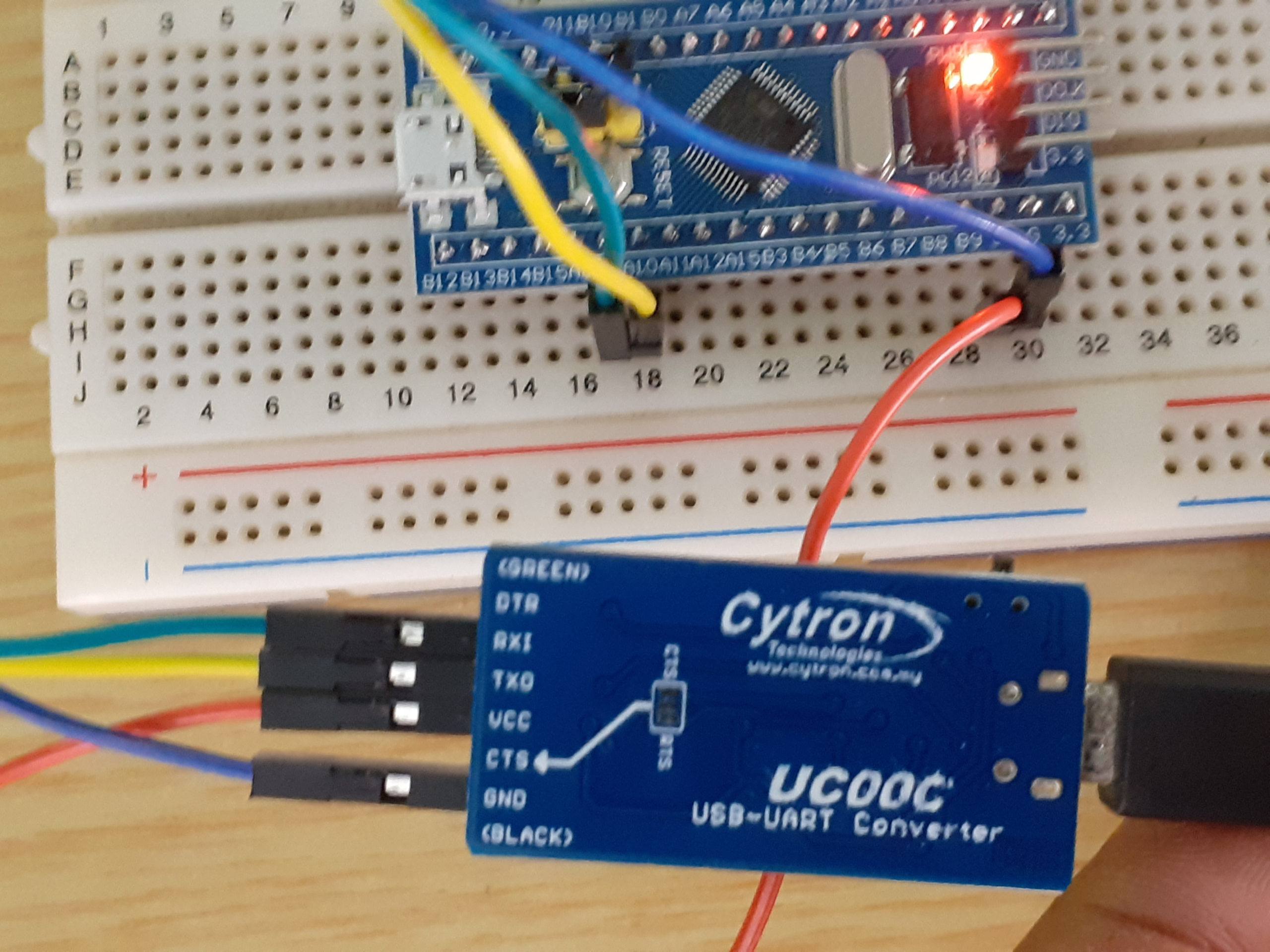
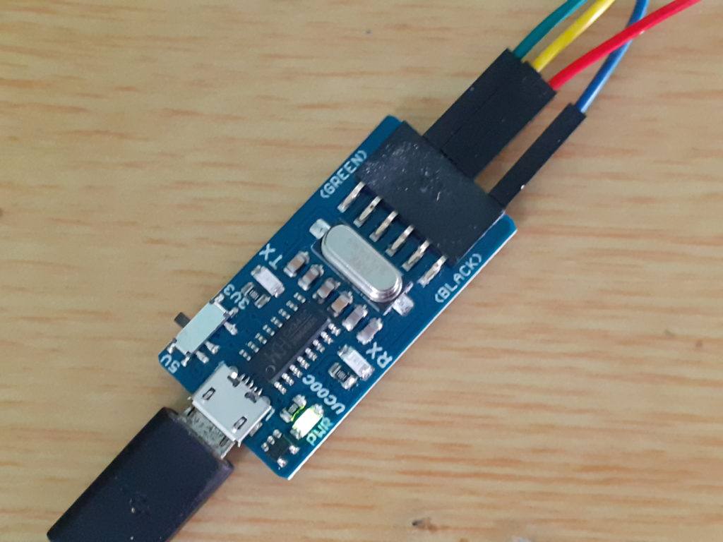
You can, however, use a USB to UART converter to upload code to the board. I have used Cytron’s UC00C, which has a selector switch to select the UART voltage between 5v and 3v3.

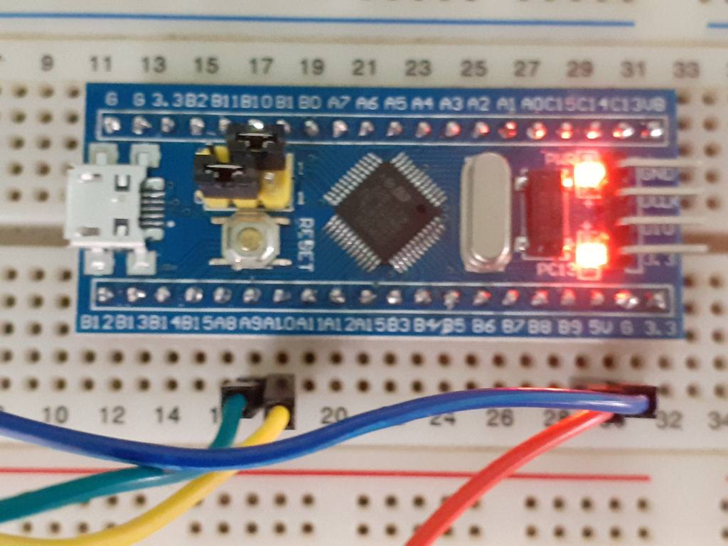
My connections are as follows
| UART PIN | “Blue Pill” Pin |
| VCC (Red) | 5v or 3v, depending on UART Selector switch setting |
| GND(Blue) | Any GND Pin |
| TxD(Yellow) | Pin A10 (RxD) |
| RxD(Green) | Pin A9 (TxD) |
Be sure that you dont connect 5v to a 3v3 pin, as you will damage the development board!
Configure the Arduino IDE
Next is to configure the Arduino IDE to allow us to write code and upload it to the STM32
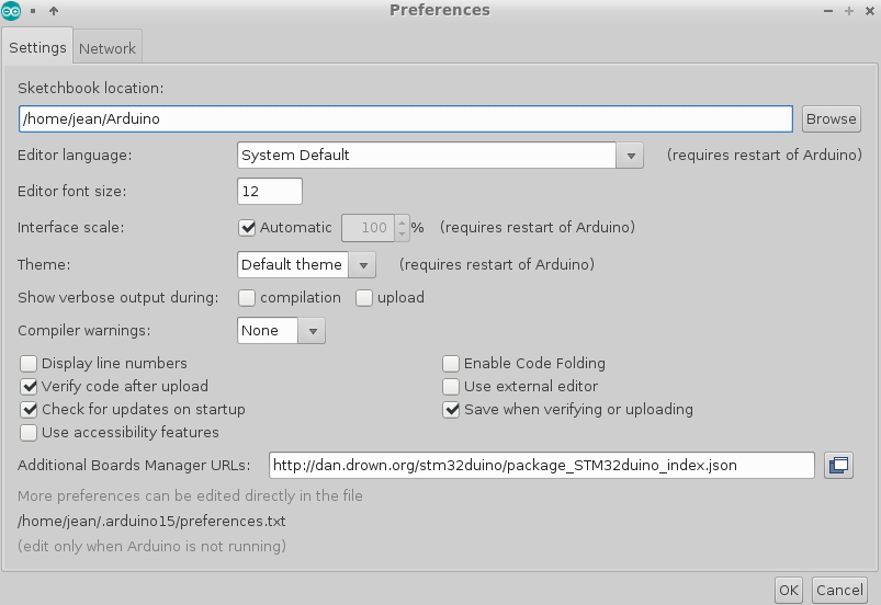
Open the IDE and Click on File -> Preferences
Paste the following url
http://dan.drown.org/stm32duino/package_STM32duino_index.jsoninto the additional board manager URL list and click on OK
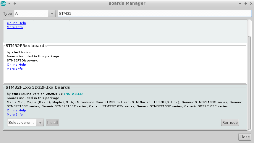
Then Click on Tools -> Board: -> Boards Manager
Type STM32 and select STM32F1xx/GD32F1xx by stm32duino
Click on install and when that is done, click on close
Close and restart the Arduino IDE.
Programming the “Blue Pill”
You are now ready to program the “Blue Pill” board with the Arduino IDE
To test it, Click on File -> Examples -> A_STM32_Examples->Digital->Blink
Please change PB1 to PC13 in the code, as our builtin led is connected to pin 13 on port c ( other boards may be different )
Click on Tools->Board: and select Generic-STM32F103C Series
Click on Tools->Upload Method and Select “Serial”
Change the jumpers on the “Blue Pill” as in the photograph to enable us to upload to system memory.
Plug the usb cable into the usart and computer, the red power light will light up.
Click Tools->Port and select the port of the USB to UART converter.
Now you may click on upload and if you are lucky the led will start flashing once a second, as programmed …
Change back the jumpers to their original position to have the board automatically run your code at startup
On Linux ( Ubuntu 18.04 ) I was not so lucky to have it work immediately, and after some additional reading and testing, found that there is some issue with the CH340 USB UART Chip and Linux CH340 Driver. I have a similar issue with ESP32 Wroom Modules..
The workaround is easy, but a bit of a pain. Press and hold down the reset button on the “Blue Pill”
Click and Hold Upload button in the IDE, Release Reset Button and Then Upload .. All should be well …
I hope this helps someone. Please note that this may not be an issue with Windows, but i wont know as my OS of choice is Linux.
By the way, there is an Arduino bootloader available to enable you to upload software to the “Blue Pill” via the USB port. In my next tutorial, I will show you how to use the Native USB Port