

Introduction
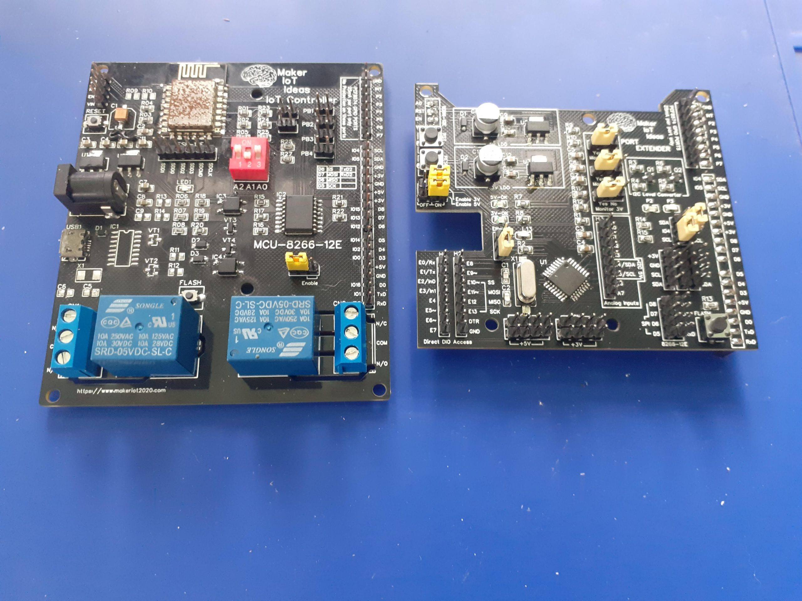
After quite a few experiments, and playing with a lot of ideas, we have finally produced and tested an almost final prototype for the MCU-8266-12E IoT Controller Port Extender Card. While the baseboard already has quite a lot of free GPIO pins for additional sensors and devices, It did however have quite a few issues, namely a lack of sufficient Power outputs, difficulty access to the I2C bus, as well as only 2 relay outputs. Granted that you do have access to unused pins on the PCF8574 Port Extender, We nonetheless decided that an add-on card would definitely make sense to allow this device to really be more useable.
While looking at various ideas for this card, the most flexible seemed to be the APE Protocol device as documented in ESPHome. They used a standard Arduino board for that, but we decided that, after testing it with an Arduino Nano, since it seems to work well, let us just design a dedicated PCB. It also looks much better as well 🙂

Some Features (Aside from being a fully functional Arduino clone as well)
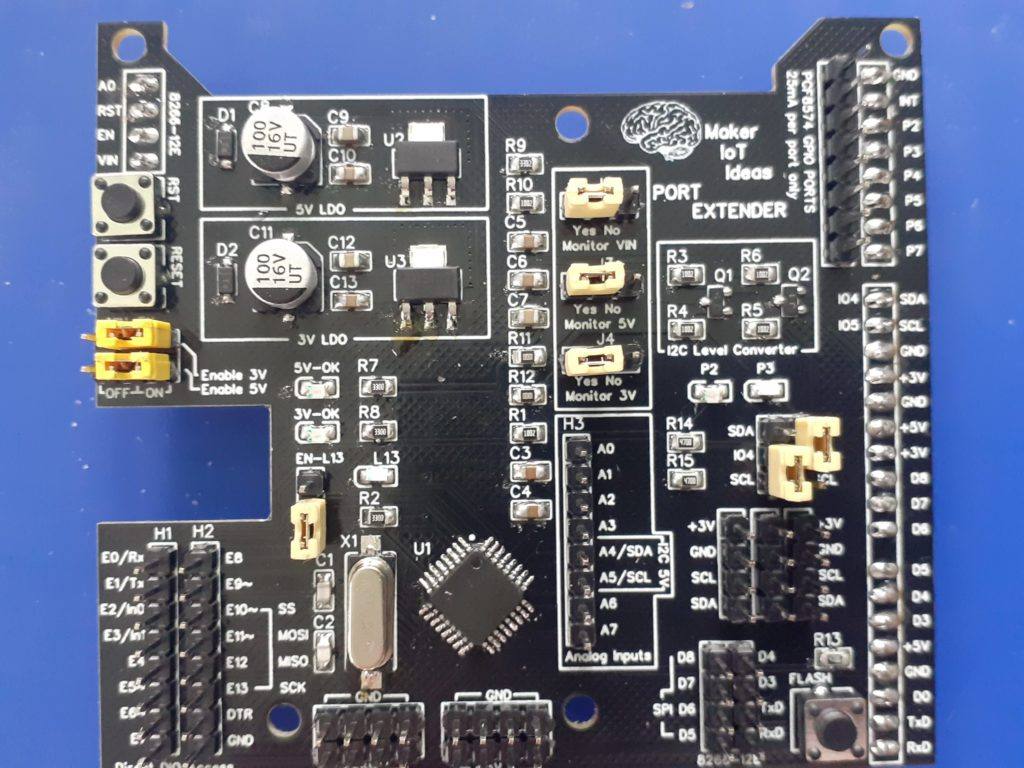
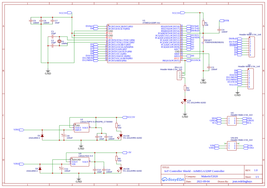
1). Dedicated LDO Regulators for 5v and 3.3v (800mA each), with jumpers to switch them on or off (receive power only from the IoT Motherboard).
2.) Dedicated Logic Level Converter on the I2C Bus ( This is sort of very much needed 🙂 The Atmega 328P-AU is running at 5v on this device, to enable it to run at 16Mhz.. and the ESP8266 on the Motherboard is a 3.3v device..
There are also 3x 3.3V I2C Headers, complete with 3.3v and Ground, as well as a single 5v I2C header
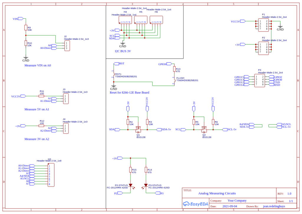
3). 8 Analog Inputs ( While practically you can only use 6 of these if you use I2C )
4). Voltage Divider provided on A0 to measure VIN ( to be safe, we calculated the resistors for 22v)
5). 100R current limiting resistor on A1 and A2, to measure 5v and 3.3v as well…
Analog inputs A0, A1 and A2 can be switched back to normal operation by changing the jumper at J2,J3 or J4 from On to Off.
6). 12 Digital Inputs/Outputs (14 if you use D0 and D1 as well), as well as a Jumper to remove the LED on D13.
7). Full access to the PCF8574 and ESP8266 Pins from the motherboard below.
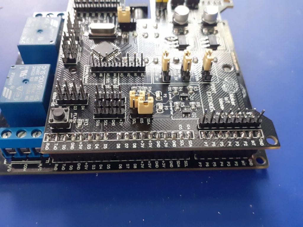
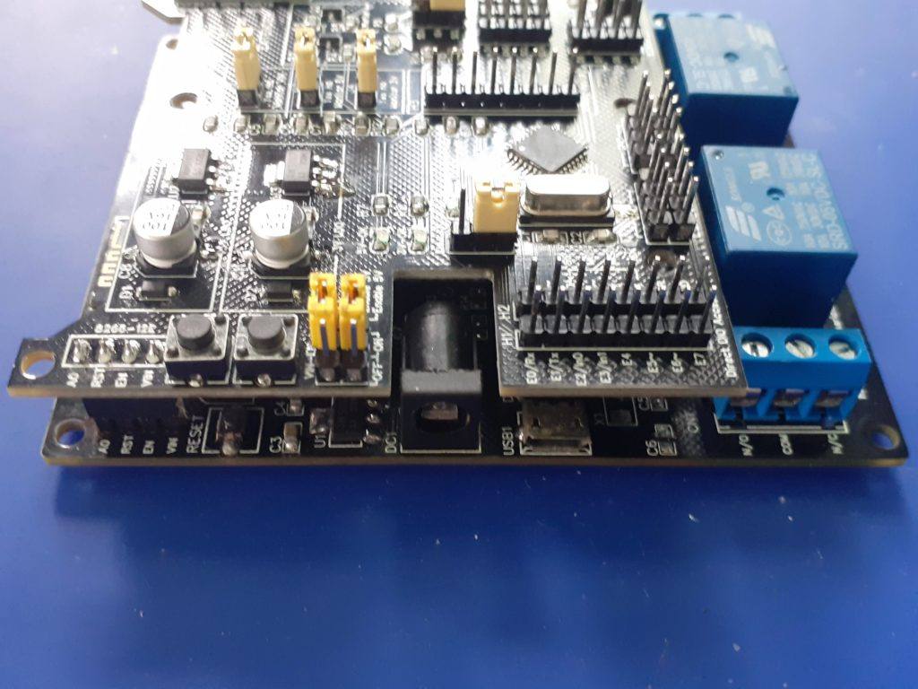
Pictures of the PCB

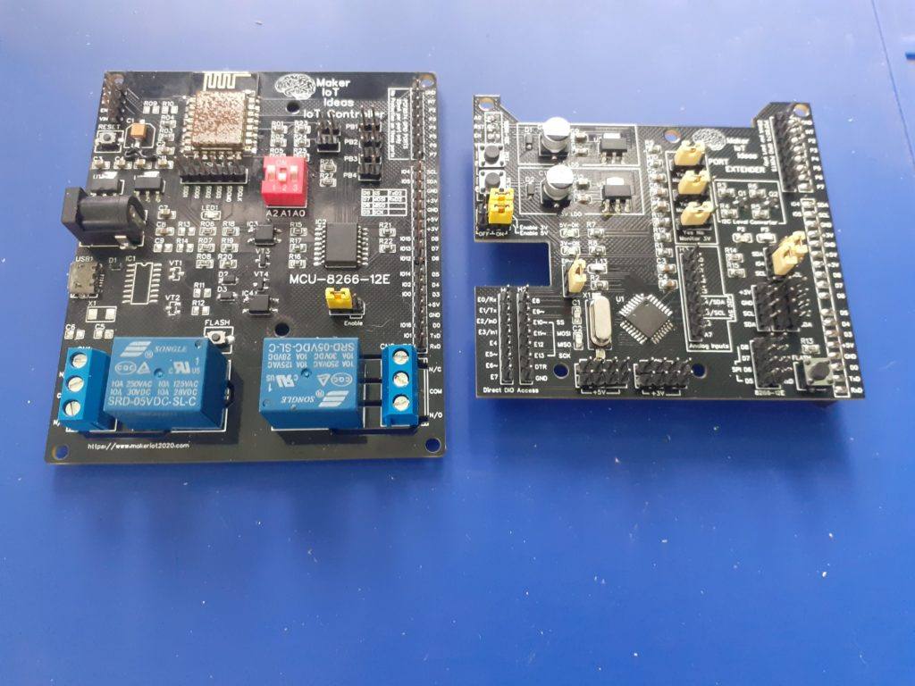
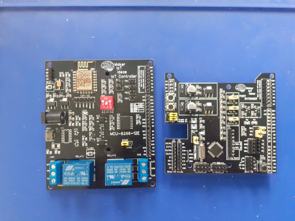
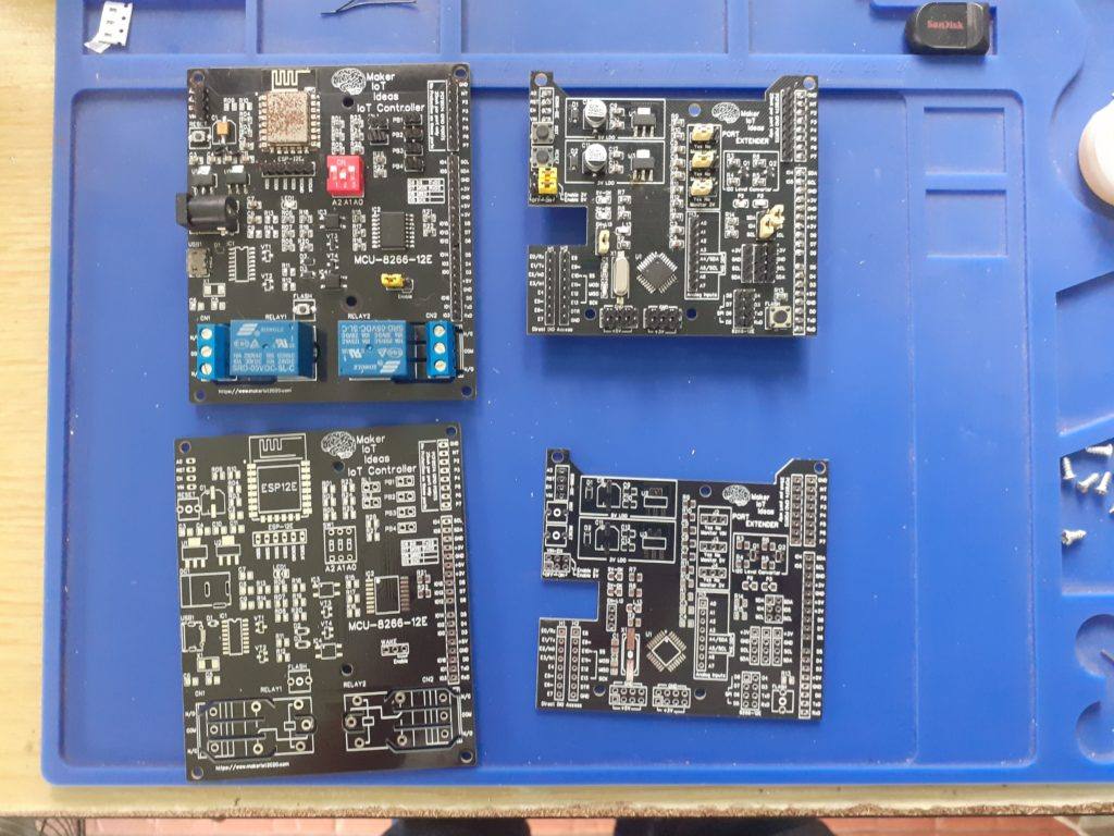
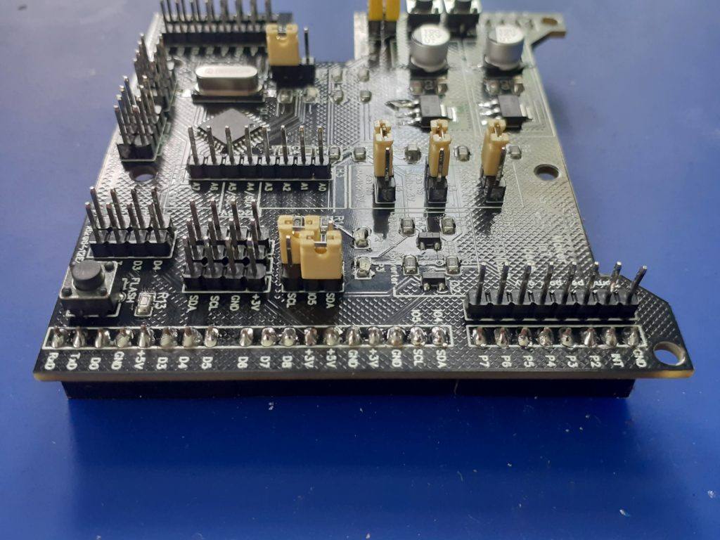
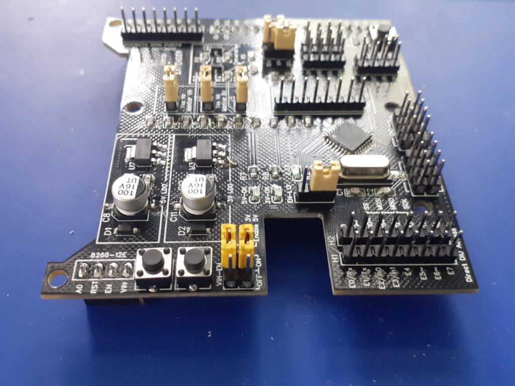
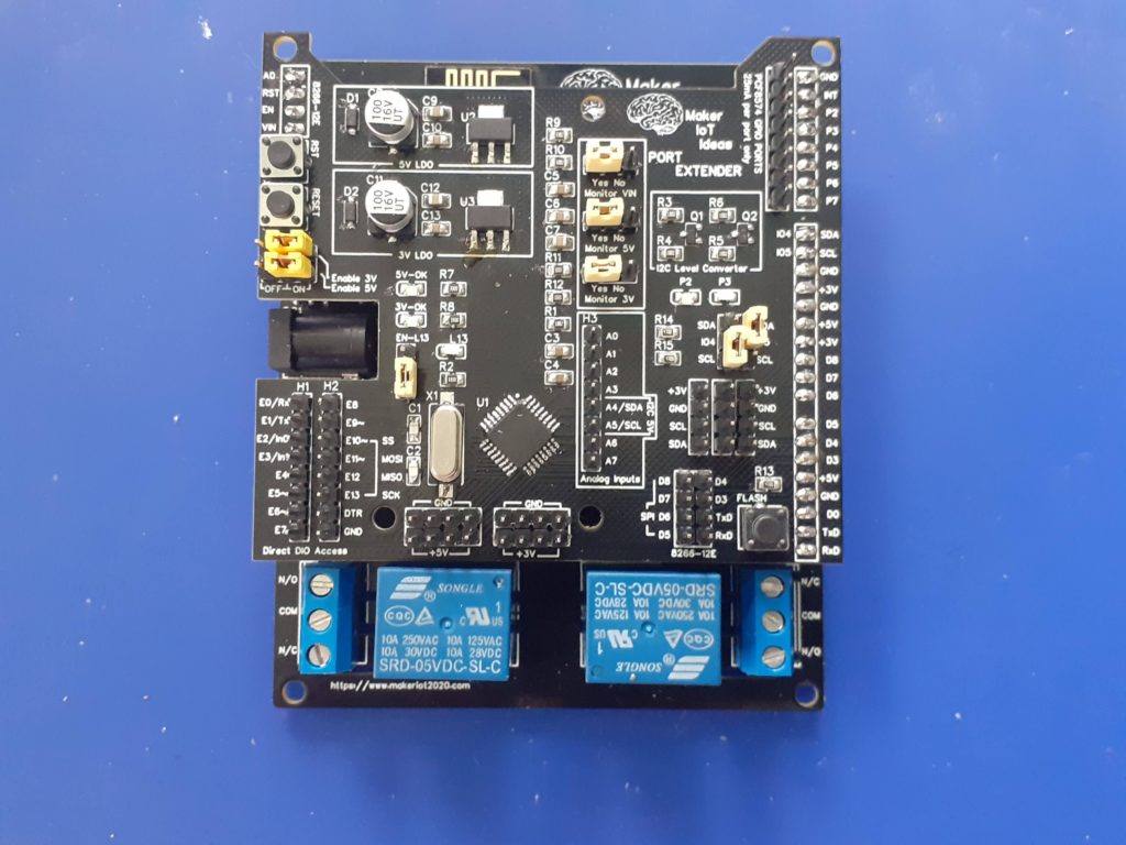
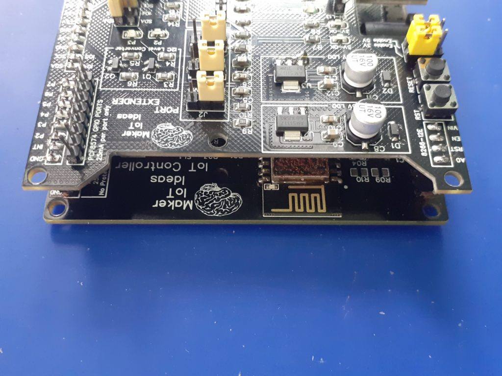
Side by side MCU-8266-12E (left) 8266-12E-Port Extender (right) Side by side MCU-8266-12E (left) 8266-12E-Port Extender (right) Side by side MCU-8266-12E (left) 8266-12E-Port Extender (right)
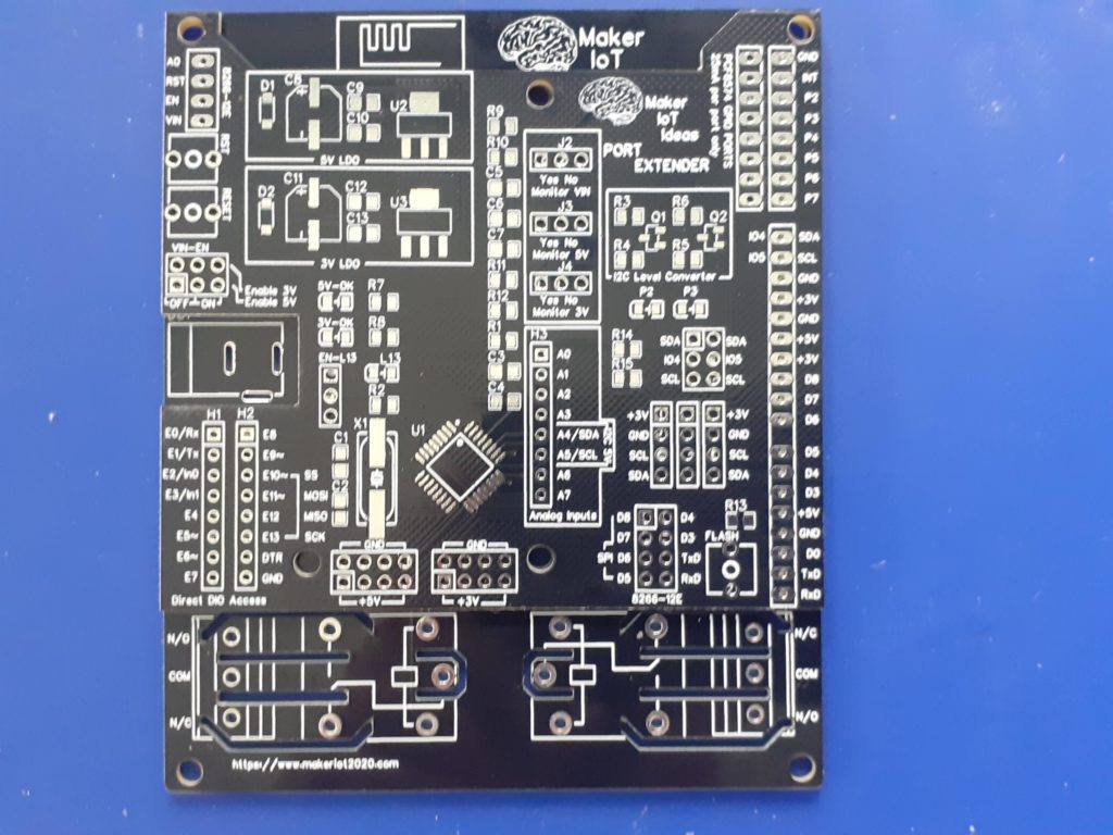
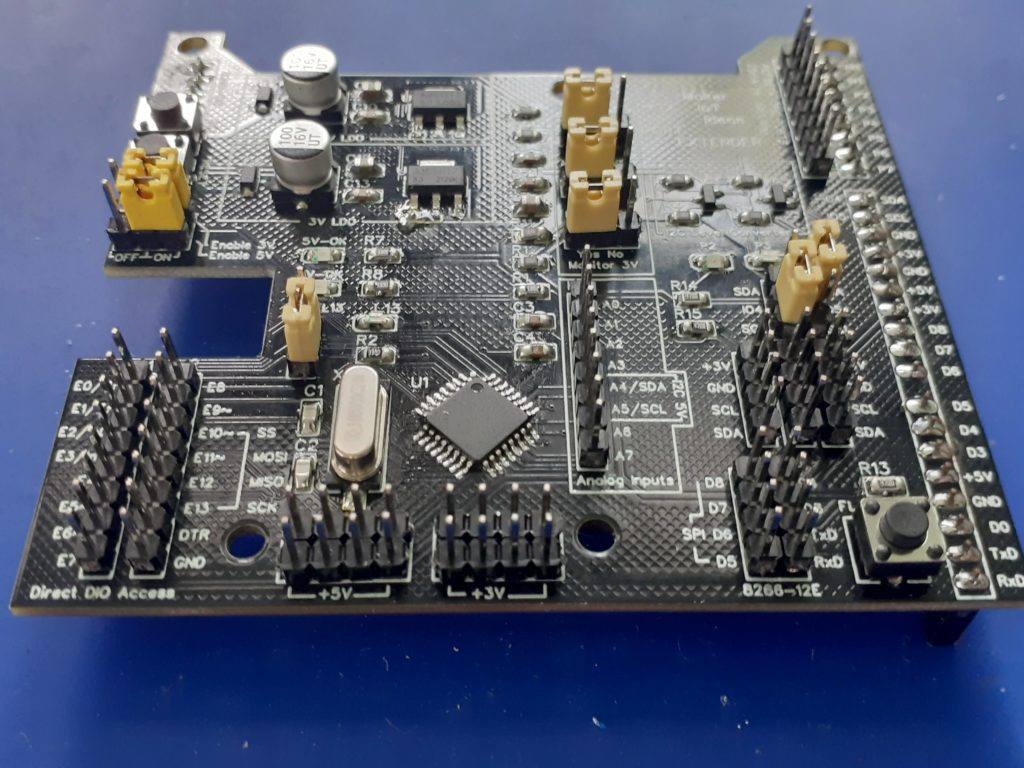
[ with unpopulated PCB at bottom]Blank PCB 8266-12E-Port Extender Blank PCB MCU-8266-12E IoT Controller Top view 8266-12E PE 8266-12E-PE side view { from bottom) Right side view – 8266-12E-PE Left side view – 8266-12E-PE Stacked on-top-of MCU-8266-12E Stacked – Top Side view Stacked – Right side view Stacked – Left side view

Circuit Diagram
Uploading Code to the ATMega328P
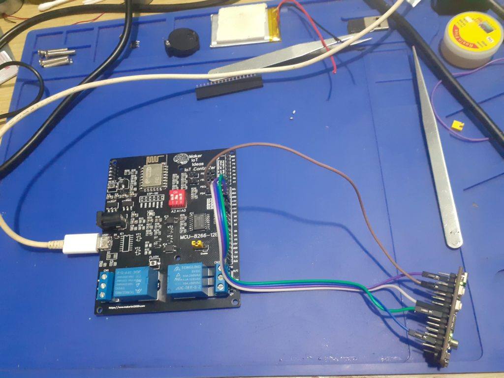
Uploading code to the device requires the use of either an ISCP programmer ( Arduino as ISP works well ) or in the case of a pre-boot loaded chip, a USB-to-Serial converter. We did not find it necessary to add a dedicated USB-to-Serial converter onto the PCB. It is quite easy enough to do any flashing with the tools mentioned above.
Make sure that the PCB is not stacked when doing this. ( This will prevent excessive current use of other components when you supply 5v to the PE card.
Procedure to upload using ICSP
During assembly, you are required to solder a single 90-degree bend pin header on the bottom side of the PCB, in the same hole as the board side edge of the RESET push-button. This will serve as the RESET Pin for the ISCP. Other connections are as follows:
H2 Header <- > ICSP Programmer
MOSI (E11~) – MOSI ( or Pin 11 on Arduino as ISP )
MISO (E12 ) – MISO ( or Pin 12 on Arduino as ISP )
SCK (E13) – D13 (or Pin 13 on Arduino as ISP )
RESET – D10 (or Pin 10 on Arduino as ISP )
5v and Ground from Arduino as ISP or ISCP Programmer to any 5v and ground pin on the PE Card
Please note the description above for assembly of the RESET pin header
Procedure to upload using USB-to-Serial converter
H1 Header
E0/Rx <- to Tx of USB-to-Serial converter
E1/Tx -> to Rx of USB-to-Serial converter
H2 Header
DTR <-> to DTR of USB-to-Serial converter [ This connection is needed for successful uploading. Don’t leave it out ]
5v and Ground from the USB-to-Serial converter to any 5v and ground pin on the PE Card
Testing with ESPHome APE protocol and the MCU-8266-12E IoT controller
The following Arduino Sketch needs to be uploaded to the device.
It will allow the device to function as a custom I2C device. Feel free to change the I2C address in the sketch as you choose, but remember to use the same address in your ESPHome YAML configuration file
/*
Ports:
  0 0 .. 13 13
  A0: 14, A1: 15, A2: 16, A3: 17: A4: 18: A5: 19: A6: 20, A7: 21
  port bits: 5 ... 0..32
  0:   0: 00000
  1:   1: 00001
  A7: 21: 10101
*/

#include <Arduino.h>
#include <Wire.h>

//#define DEBUG // remove debug so pin 0 and 1 can be used for IO

#define I2C_ADDRESS 8

void onRequest();
void onReceive(int);

void setup()
{
#ifdef DEBUG
  Serial.begin(115200);
  Serial.println(F("Init "));
#endif

  analogReference(INTERNAL);

  Wire.begin(I2C_ADDRESS);
  Wire.onRequest(onRequest);
  Wire.onReceive(onReceive);

#ifdef DEBUG
  Serial.println(F("Wire ok"));
#endif
}

void loop()
{
  //int temp = analogRead(A1);
  //Serial.println(temp);
}

volatile byte buffer[3];
volatile byte len = 1;

#define DIGITAL_READ(b, pin, mask) \
  if (digitalRead(pin))            \
    buffer[b] |= mask;

void readDigital()
{
  len = 3;
  buffer[0] = 0;
  DIGITAL_READ(0, 0, 1);
  DIGITAL_READ(0, 1, 2);
  DIGITAL_READ(0, 2, 4);
  DIGITAL_READ(0, 3, 8);
  DIGITAL_READ(0, 4, 16);
  DIGITAL_READ(0, 5, 32);
  DIGITAL_READ(0, 6, 64);
  DIGITAL_READ(0, 7, 128);

  buffer[1] = 0;
  DIGITAL_READ(1, 8, 1);
  DIGITAL_READ(1, 9, 2);
  DIGITAL_READ(1, 10, 4);
  DIGITAL_READ(1, 11, 8);
  DIGITAL_READ(1, 12, 16);
  DIGITAL_READ(1, 13, 32);
  DIGITAL_READ(1, A0, 64);
  DIGITAL_READ(1, A1, 128);

  buffer[2] = 0;
  DIGITAL_READ(2, A2, 1);
  DIGITAL_READ(2, A3, 2);

// I2C
//DIGITAL_READ(2, A4, 4);
//DIGITAL_READ(2, A5, 8);

// DIGITAL READ not supports on A3 .. A7
#ifdef DEBUG_READ
  Serial.print(F("Read 3 bytes: "));
  Serial.print(buffer[0]);
  Serial.print(' ');
  Serial.print(buffer[1]);
  Serial.print(' ');
  Serial.println(buffer[2]);

#endif
}
void readAnalog(int pin)
{
  int val = analogRead(A0 + pin);
  len = 2;
  buffer[0] = val & 0xFF;
  buffer[1] = (val >> 8) & 0b11;
#ifdef DEBUG_READ
  Serial.print(F("Read analog pin "));
  Serial.println(pin);
#endif
}

void onRequest()
{
  Wire.write(const_cast<uint8_t *>(buffer), len);
}

#define CMD_DIGITAL_READ 0x0

#define CMD_WRITE_ANALOG 0x2
#define CMD_WRITE_DIGITAL_HIGH 0x3
#define CMD_WRITE_DIGITAL_LOW 0x4

#define CMD_SETUP_PIN_OUTPUT 0x5
#define CMD_SETUP_PIN_INPUT_PULLUP 0x6
#define CMD_SETUP_PIN_INPUT 0x7

// 8 analog registers.. A0 to A7
// A4 and A5 not supported due to I2C
#define CMD_ANALOG_READ_A0 0b1000 // 0x8
// ....
#define CMD_ANALOG_READ_A7 0b1111 // 0xF

#define CMD_SETUP_ANALOG_INTERNAL 0x10
#define CMD_SETUP_ANALOG_DEFAULT 0x11

void onReceive(int numBytes)
{
#ifdef DEBUG_READ
  Serial.print("Received bytes: ");
  Serial.println(numBytes);
#endif
  int cmd = Wire.read();

  switch (cmd)
  {
  case CMD_DIGITAL_READ:
    readDigital();
    break;
  }

  if (cmd >= CMD_ANALOG_READ_A0 && cmd <= CMD_ANALOG_READ_A7)
  {
    readAnalog(cmd & 0b111);
    return;
  }

  int pin = Wire.read();

  switch (cmd)
  {
  case CMD_WRITE_DIGITAL_HIGH:
  case CMD_WRITE_DIGITAL_LOW:
  {
    bool output = cmd == CMD_WRITE_DIGITAL_HIGH;
    digitalWrite(pin, output);
#ifdef DEBUG
    Serial.print(F("Pin "));
    Serial.print(pin);
    Serial.println(output ? F(" HIGH") : F(" LOW"));
#endif
    break;
  }
  case CMD_WRITE_ANALOG:
  {
    int val = Wire.read() & (Wire.read() << 8);
    analogWrite(pin, val);
#ifdef DEBUG
    Serial.print(F("Pin "));
    Serial.print(pin);
    Serial.print(F(" Analog write "));
    Serial.println(val);
#endif
    break;
  }
  case CMD_SETUP_PIN_OUTPUT:
    pinMode(pin, OUTPUT);
#ifdef DEBUG
    Serial.print(F("Pin "));
    Serial.print(pin);
    Serial.println(F(" OUTPUT"));
#endif
    break;
  case CMD_SETUP_PIN_INPUT:
    pinMode(pin, INPUT);
#ifdef DEBUG
    Serial.print(F("Pin "));
    Serial.print(pin);
    Serial.println(F("INPUT"));
#endif
    break;
  case CMD_SETUP_PIN_INPUT_PULLUP:
    pinMode(pin, INPUT_PULLUP);
#ifdef DEBUG
    Serial.print(F("Pin "));
    Serial.print(pin);
    Serial.println(F("INPUT PULLUP"));
#endif
    break;
  case CMD_SETUP_ANALOG_INTERNAL:
    analogReference(INTERNAL);
#ifdef DEBUG
    Serial.println(F("Analog reference INTERNAL"));
#endif
    break;
  case CMD_SETUP_ANALOG_DEFAULT:
    analogReference(DEFAULT);
#ifdef DEBUG
    Serial.println(F("Analog reference DEFAULT"));
#endif
    break;
  }
}
The following C header file needs to be uploaded to your Home Assistant ESPHome folder.
// Must disable logging if using logging in main.cpp or in other custom components for the
//  __c causes a section type conflict with __c thingy
// you can enable logging and use it if you enable this in logger:
/*
logger:
  level: DEBUG
  esp8266_store_log_strings_in_flash: False
  */

//#define APE_LOGGING

// take advantage of LOG_ defines to decide which code to include
#ifdef LOG_BINARY_OUTPUT
#define APE_BINARY_OUTPUT
#endif
#ifdef LOG_BINARY_SENSOR
#define APE_BINARY_SENSOR
#endif
#ifdef LOG_SENSOR
#define APE_SENSOR
#endif

static const char *TAGape = "ape";

#define APE_CMD_DIGITAL_READ 0
#define APE_CMD_WRITE_ANALOG 2
#define APE_CMD_WRITE_DIGITAL_HIGH 3
#define APE_CMD_WRITE_DIGITAL_LOW 4
#define APE_CMD_SETUP_PIN_OUTPUT 5
#define APE_CMD_SETUP_PIN_INPUT_PULLUP 6
#define APE_CMD_SETUP_PIN_INPUT 7
// 8 analog registers.. A0 to A7
// A4 and A5 not supported due to I2C
#define CMD_ANALOG_READ_A0 0b1000 // 0x8
// ....
#define CMD_ANALOG_READ_A7 0b1111 // 0xF

#define CMD_SETUP_ANALOG_INTERNAL 0x10
#define CMD_SETUP_ANALOG_DEFAULT 0x11

#define get_ape(constructor) static_cast<ArduinoPortExpander *>(constructor.get_component(0))

#define ape_binary_output(ape, pin) get_ape(ape)->get_binary_output(pin)
#define ape_binary_sensor(ape, pin) get_ape(ape)->get_binary_sensor(pin)
#define ape_analog_input(ape, pin) get_ape(ape)->get_analog_input(pin)

class ArduinoPortExpander;

using namespace esphome;

#ifdef APE_BINARY_OUTPUT
class ApeBinaryOutput : public output::BinaryOutput
{
public:
  ApeBinaryOutput(ArduinoPortExpander *parent, uint8_t pin)
  {
    this->parent_ = parent;
    this->pin_ = pin;
  }
  void write_state(bool state) override;
  uint8_t get_pin() { return this->pin_; }

protected:
  ArduinoPortExpander *parent_;
  uint8_t pin_;
  // Pins are setup as output after the state is written, Arduino has no open drain outputs, after setting an output it will either sink or source thus activating outputs writen to false during a flick.
  bool setup_{true};
  bool state_{false};

  friend class ArduinoPortExpander;
};
#endif

#ifdef APE_BINARY_SENSOR
class ApeBinarySensor : public binary_sensor::BinarySensor
{
public:
  ApeBinarySensor(ArduinoPortExpander *parent, uint8_t pin)
  {
    this->pin_ = pin;
  }
  uint8_t get_pin() { return this->pin_; }

protected:
  uint8_t pin_;
};
#endif

#ifdef APE_SENSOR
class ApeAnalogInput : public sensor::Sensor
{
public:
  ApeAnalogInput(ArduinoPortExpander *parent, uint8_t pin)
  {
    this->pin_ = pin;
  }
  uint8_t get_pin() { return this->pin_; }

protected:
  uint8_t pin_;
};
#endif

class ArduinoPortExpander : public Component, public I2CDevice
{
public:
  ArduinoPortExpander(I2CBus *bus, uint8_t address, bool vref_default = false)
  {
    set_i2c_address(address);
    set_i2c_bus(bus);
    this->vref_default_ = vref_default;
  }
  void setup() override
  {
#ifdef APE_LOGGING
    ESP_LOGCONFIG(TAGape, "Setting up ArduinoPortExpander at %#02x ...", address_);
#endif

    /* We cannot setup as usual as arduino boots later than esp8266
            Poll i2c bus for our Arduino for a n seconds instead of failing fast,
            also this is important as pin setup (INPUT_PULLUP, OUTPUT it's done once)
        */
    this->configure_timeout_ = millis() + 5000;
  }
  void loop() override
  {
    if (millis() < this->configure_timeout_)
    {
      bool try_configure = millis() % 100 > 50;
      if (try_configure == this->configure_)
        return;
      this->configure_ = try_configure;

      if (ERROR_OK == this->read_register(APE_CMD_DIGITAL_READ, const_cast<uint8_t *>(this->read_buffer_), 3))
      {
#ifdef APE_LOGGING
        ESP_LOGCONFIG(TAGape, "ArduinoPortExpander found at %#02x", address_);
#endif
        delay(10);
        if (this->vref_default_)
        {
          this->write_register(CMD_SETUP_ANALOG_DEFAULT, nullptr, 0); // 0: unused
        }

        // Config success
        this->configure_timeout_ = 0;
        this->status_clear_error();
#ifdef APE_BINARY_SENSOR
        for (ApeBinarySensor *pin : this->input_pins_)
        {
          App.feed_wdt();
          uint8_t pinNo = pin->get_pin();
#ifdef APE_LOGGING
          ESP_LOGCONFIG(TAGape, "Setup input pin %d", pinNo);
#endif
          this->write_register(APE_CMD_SETUP_PIN_INPUT_PULLUP, &pinNo, 1);
          delay(20);
        }
#endif
#ifdef APE_BINARY_OUTPUT
        for (ApeBinaryOutput *output : this->output_pins_)
        {
          if (!output->setup_)
          { // this output has a valid value already
            this->write_state(output->pin_, output->state_, true);
            App.feed_wdt();
            delay(20);
          }
        }
#endif
#ifdef APE_SENSOR
        for (ApeAnalogInput *sensor : this->analog_pins_)
        {
          App.feed_wdt();
          uint8_t pinNo = sensor->get_pin();
#ifdef APE_LOGGING
          ESP_LOGCONFIG(TAGape, "Setup analog input pin %d", pinNo);
#endif
          this->write_register(APE_CMD_SETUP_PIN_INPUT, &pinNo, 1);
          delay(20);
        }
#endif
        return;
      }
      // Still not answering
      return;
    }
    if (this->configure_timeout_ != 0 && millis() > this->configure_timeout_)
    {
#ifdef APE_LOGGING
      ESP_LOGE(TAGape, "ArduinoPortExpander NOT found at %#02x", address_);
#endif
      this->mark_failed();
      return;
    }

#ifdef APE_BINARY_SENSOR
    if (ERROR_OK != this->read_register(APE_CMD_DIGITAL_READ, const_cast<uint8_t *>(this->read_buffer_), 3))
    {
#ifdef APE_LOGGING
      ESP_LOGE(TAGape, "Error reading. Reconfiguring pending.");
#endif
      this->status_set_error();
      this->configure_timeout_ = millis() + 5000;
      return;
    }
    for (ApeBinarySensor *pin : this->input_pins_)
    {
      uint8_t pinNo = pin->get_pin();

      uint8_t bit = pinNo % 8;
      uint8_t value = pinNo < 8 ? this->read_buffer_[0] : pinNo < 16 ? this->read_buffer_[1] : this->read_buffer_[2];
      bool ret = value & (1 << bit);
      if (this->initial_state_)
        pin->publish_initial_state(ret);
      else
        pin->publish_state(ret);
    }
#endif
#ifdef APE_SENSOR
    for (ApeAnalogInput *pin : this->analog_pins_)
    {
      uint8_t pinNo = pin->get_pin();
      pin->publish_state(analogRead(pinNo));
    }
#endif
    this->initial_state_ = false;
  }

#ifdef APE_SENSOR
  uint16_t analogRead(uint8_t pin)
  {
    bool ok = (ERROR_OK == this->read_register((uint8_t)(CMD_ANALOG_READ_A0 + pin), const_cast<uint8_t *>(this->read_buffer_), 2));
#ifdef APE_LOGGING
    ESP_LOGVV(TAGape, "analog read pin: %d ok: %d byte0: %d byte1: %d", pin, ok, this->read_buffer_[0], this->read_buffer_[1]);
#endif
    uint16_t value = this->read_buffer_[0] | ((uint16_t)this->read_buffer_[1] << 8);
    return value;
  }
#endif

#ifdef APE_BINARY_OUTPUT
  output::BinaryOutput *get_binary_output(uint8_t pin)
  {
    ApeBinaryOutput *output = new ApeBinaryOutput(this, pin);
    output_pins_.push_back(output);
    return output;
  }
#endif
#ifdef APE_BINARY_SENSOR
  binary_sensor::BinarySensor *get_binary_sensor(uint8_t pin)
  {
    ApeBinarySensor *binarySensor = new ApeBinarySensor(this, pin);
    input_pins_.push_back(binarySensor);
    return binarySensor;
  }
#endif
#ifdef APE_SENSOR
  sensor::Sensor *get_analog_input(uint8_t pin)
  {
    ApeAnalogInput *input = new ApeAnalogInput(this, pin);
    analog_pins_.push_back(input);
    return input;
  }
#endif
  void write_state(uint8_t pin, bool state, bool setup = false)
  {
    if (this->configure_timeout_ != 0)
      return;
#ifdef APE_LOGGING
    ESP_LOGD(TAGape, "Writing %d to pin %d", state, pin);
#endif
    this->write_register(state ? APE_CMD_WRITE_DIGITAL_HIGH : APE_CMD_WRITE_DIGITAL_LOW, &pin, 1);
    if (setup)
    {
      App.feed_wdt();
      delay(20);
#ifdef APE_LOGGING
      ESP_LOGI(TAGape, "Setup output pin %d", pin);
#endif
      this->write_register(APE_CMD_SETUP_PIN_OUTPUT, &pin, 1);
    }
  }

protected:
  bool configure_{true};
  bool initial_state_{true};
  uint8_t read_buffer_[3]{0, 0, 0};
  unsigned long configure_timeout_{5000};
  bool vref_default_{false};

#ifdef APE_BINARY_OUTPUT
  std::vector<ApeBinaryOutput *> output_pins_;
#endif
#ifdef APE_BINARY_SENSOR
  std::vector<ApeBinarySensor *> input_pins_;
#endif
#ifdef APE_SENSOR
  std::vector<ApeAnalogInput *> analog_pins_;
#endif
};

#ifdef APE_BINARY_OUTPUT
void ApeBinaryOutput::write_state(bool state)
{
  this->state_ = state;
  this->parent_->write_state(this->pin_, state, this->setup_);
  this->setup_ = false;
}
#endif
The file should be named “arduino_port_expander.h”
Make the following changes to your ESPHome YAML configuration file for the MCU-8266-12E device
esphome:
  name: mcu-8266-12e-01
  platform: ESP8266
  board: nodemcuv2
  includes:
      - arduino_port_expander.h
# Note the include file - This loads the APE Header

# Enable logging
logger:

# Enable Home Assistant API
api:

ota:
  password: "<your password will be different - dont change it>"

wifi:
  ssid: <your ssid>
  password: <your password>

  # Enable fallback hotspot (captive portal) in case wifi connection fails
  ap:
    ssid: "MCU-8266-Hotspot"
    password: "password"

captive_portal:

i2c:
# PCB Prototype
  sda: GPIO5
  scl: GPIO4
# PCB Rev 1.5 or higher, comment the above 2 lines
# and uncomment
#sda: GPIO4
#scl: GPIO5
#################### - IMPORTANT ###########
  scan: true
  id: i2c_bus_a

pcf8574:
  - id: 'pcf8574_hub'
    address: 0x22 # Set at 0x22, feel free to change to your liking, Remember to set the chip to the address you choose as well
    pcf8575: false

time:
  - platform: sntp
    id: ha_time
    timezone: "Etc/GMT+7"

status_led:
  pin:
    number: GPIO16
    inverted: true

#Define the APE as a custom component, taking care to ensure that:
#1). The I2C Bust ID is the same as the one you have defined in the I2C: Section
#2). The address of the APE is the same as the one you set in the sketch

custom_component:
  - id: ape
    lambda: |-
      auto ape_component = new ArduinoPortExpander(i2c_bus_a, 0x08,true);
      return {ape_component};


sensor:

  - platform: custom
    lambda: |-
      return {ape_analog_input(ape, 0),  // 1 = A1
             ape_analog_input(ape, 1),
             ape_analog_input(ape, 2)};

#We define 3 analog inputs (A0,A1,A2) to monitor voltages on the card
#Note that you MUST define them in the sensors section below as well AND
#THAT THEY MUST BE IN THE SAME SEQUENCE THAT YOU DEFINED THEM IN ABOVE HERE
#
#ALSO NOTE THAT YOU CAN "NOT" use A4 and A5, as they are used for I2C !
#
# As an example, of adding another 3 analog inputs, your definition above will change to:
#
#    return {ape_analog_input(ape, 0),
#           ape_analog_input(ape, 1),
#           ape_analog_input(ape, 2),
#           ape_analog_input(ape, 3),
#           ape_analog_input(ape, 6),
#           ape_analog_input(ape, 7)};
#
#
# Now define the sensors connected to these analogs below:


    sensors:
      - name: "PE Card VIN"
        id: analog_a0
        device_class: "voltage"
        unit_of_measurement: "v"
        accuracy_decimals: 2
        filters:
          - lambda: return x * (22.00/1023.0);
          - throttle: 60s

# We use a lambda to scale the value of VIN - Our Voltage divider was designed around 22 volt
# thus we need 22 volt here in the calculation as well to make it accurate
#
      - name: "PE Card 5v"
        id: analog_a1
        device_class: "voltage"
        unit_of_measurement: "v"
        accuracy_decimals: 2
        filters:
          - lambda: return x * (5.02/1023.0);
          - throttle: 60s
      - name: "PE Card 3v"
        id: analog_a2
        device_class: "voltage"
        unit_of_measurement: "v"
        accuracy_decimals: 2
        filters:
          - lambda: return x * (5.02/1023.0);
          - throttle: 60s

# The ATMega328P 's Analog Reference is set to 5v internally, thus we need to also scale the
# 3v input with a maximum of 5v ...

# In case you enabled the other 3 Analog Inputs above, you need to add the following
#
#    - name: "Analog 3"
#      id: analog_a3
#      filters:
#        - throttle: 60s
#    - name: "Analog 6"
#      id: analog_a6
#      filters:
#        - throttle: 60s
#    - name: "Analog 7"
#      id: analog_a7
#      filters:
#        - throttle: 60s
#
#


  - platform: adc
    pin: VCC
    name: "ESP8266 Chip Voltage"
    id: mcu_voltage
    unit_of_measurement: "V"
    device_class: "voltage"
    accuracy_decimals: 2
    update_interval: 60s

  - platform: wifi_signal
    name: "WiFi Signal Sensor"
    id: wifi_strength
    device_class: "signal_strength"
    unit_of_measurement: "dBm"
    update_interval: 240s


#Digital outputs function the same

output:
- platform: custom
  type: binary
  lambda: |-
    return {ape_binary_output(ape, 2),
            ape_binary_output(ape, 3),
            ape_binary_output(ape, 4),
            ape_binary_output(ape, 5),
            ape_binary_output(ape, 6),
            ape_binary_output(ape, 7)};
  outputs:
    - id: ape_output_p2
      inverted: false
    - id: ape_output_p3
      inverted: false
    - id: ape_output_p4
      inverted: false
    - id: ape_output_p5
      inverted: false
    - id: ape_output_p6
      inverted: false
    - id: ape_output_p7
      inverted: false

- platform: gpio
  id: relay_1
  pin:
    pcf8574: pcf8574_hub
    number: 0
    mode: OUTPUT
    inverted: true
- platform: gpio
  id: relay_2
  pin:
    pcf8574: pcf8574_hub
    number: 1
    mode: OUTPUT
    inverted: true
- platform: gpio
  id: led_status_1
  pin:
    pcf8574: pcf8574_hub
    number: 2
    mode: OUTPUT
    inverted: true
- platform: gpio
  id: led_status_2
  pin:
    pcf8574: pcf8574_hub
    number: 3
    mode: OUTPUT
    inverted: true

binary_sensor:
  - platform: gpio
    id: push_button_1
    name: 'Relay1 Pushbutton'
    device_class: ''
    pin:
      pcf8574: pcf8574_hub
      number: 4
      mode: INPUT
      inverted: true
    on_press:
      then:
        - switch.toggle: switch_relay1

  - platform: gpio
    id: push_button_2
    name: 'Relay2 Pushbutton'
    device_class: ''
    pin:
      pcf8574: pcf8574_hub
      number: 5
      mode: INPUT
      inverted: true
    on_press:
      #min_length: 50ms
      #max_length: 500ms
      then:
        - switch.toggle: switch_relay2
    filters:
        - delayed_on_off: 50ms


switch:
  - platform: output
    id: switch_relay1
    name: "Relay No. 1 (#0)"
    output: relay_1
    on_turn_on:
      - output.turn_on: led_status_1
    on_turn_off:
      - output.turn_off: led_status_1

  - platform: output
    id: switch_relay2
    name: "Relay No. 2 (#1)"
    output: relay_2
    on_turn_on:
      - output.turn_on: led_status_2
    on_turn_off:
      - output.turn_off: led_status_2
  - platform: restart
    id: reboot_switch
    name: "Reboot Me"
Detailed information on the APE is available here
Manufacturing the PCB
This PCB was manufactured at PCBWAY. The Gerber files and BOM, as well as all the schematics, will soon be available as a shared project on their website. If you would like to have PCBWAY manufacture one of your own, designs, or even this particular PCB, you need to do the following…
1) Click on this link
2) Create an account if you have not already got one of your own.
If you use the link above, you will also instantly receive a $5USD coupon, which you can use on your first or any other order later. (Disclaimer: I will earn a small referral fee from PCBWay. This referral fee will not affect the cost of your order, nor will you pay any part thereof.)
3) Once you have gone to their website, and created an account, or login with your existing account,

4) Click on PCB Instant Quote

5) If you do not have any very special requirements for your PCB, click on Quick-order PCB
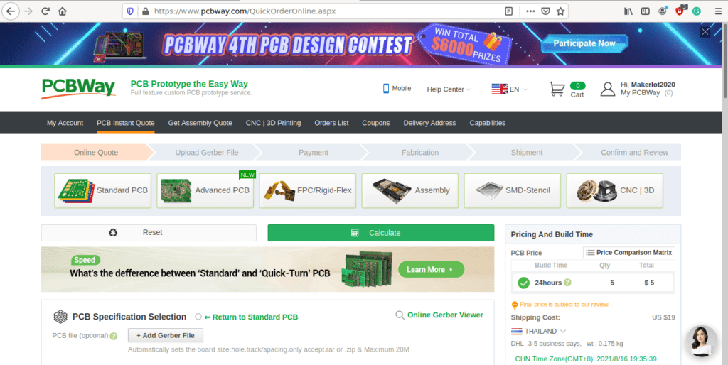
6) Click on Add Gerber File, and select your Gerber file(s) from your computer. Most of your PCB details will now be automatically selected, leaving you to only select the solder mask and silk-screen colour, as well as to remove the order number or not. You can of course fine-tune everything exactly as you want as well.


7) You can also select whether you want an SMD stencil, or have the board assembled after manufacturing. Please note that the assembly service, as well as the cost of your components, ARE NOT included in the initial quoted price. ( The quote will update depending on what options you select ).
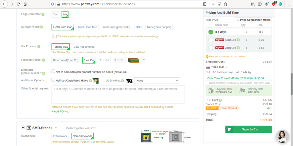

8) When you are happy with the options that you have selected, you can click on the Save to Cart Button. From here on, you can go to the top of the screen, click on Cart, make any payment(s) or use any coupons that you have in your account.
Then just sit back and wait for your new PCB to be delivered to your door via the shipping company that you have selected during checkout.