

In part one of this series, I showed you how to construct the basic logic gates using transistors and a few resistors. Today I will expand on that by showing you two very simple, but useful circuits, constructed with NAND gates, as well as a handful of other components.
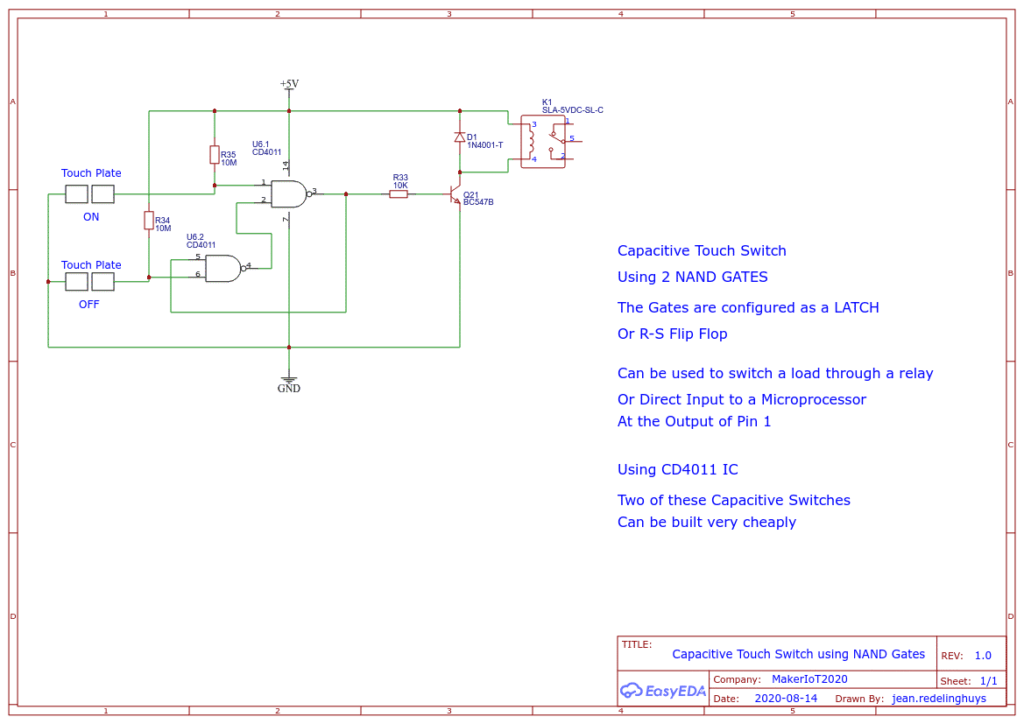
The first circuit will be a Capacitive On/OFF Switch, Based on the CD4011 CMOS Quad NAND Gate. I draw the circuit to function on 5v, but you can also change the relay and use it with a supply voltage of up to 12v DC
Let use look at the circuit
As we can see here, the two NAND gates are configured as a LATCH or R/S Flip Flop. Touching the “ON” touch plate causes a change in the input logic, making the latch change state and switching ON the output. Touching the “OFF” touch plate, resets the latch, switching the output OFF.
You can also send the input directly to a microcontroller like Arduino. In that case you would take the output at pin 1 through a resistor to the input of the microcontroller.
The circuit can also work in reverse logic, as pin 4 will be the complementary state of pin 1, thus off becomes 1 and on becomes 0
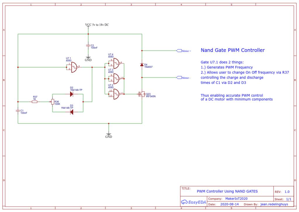
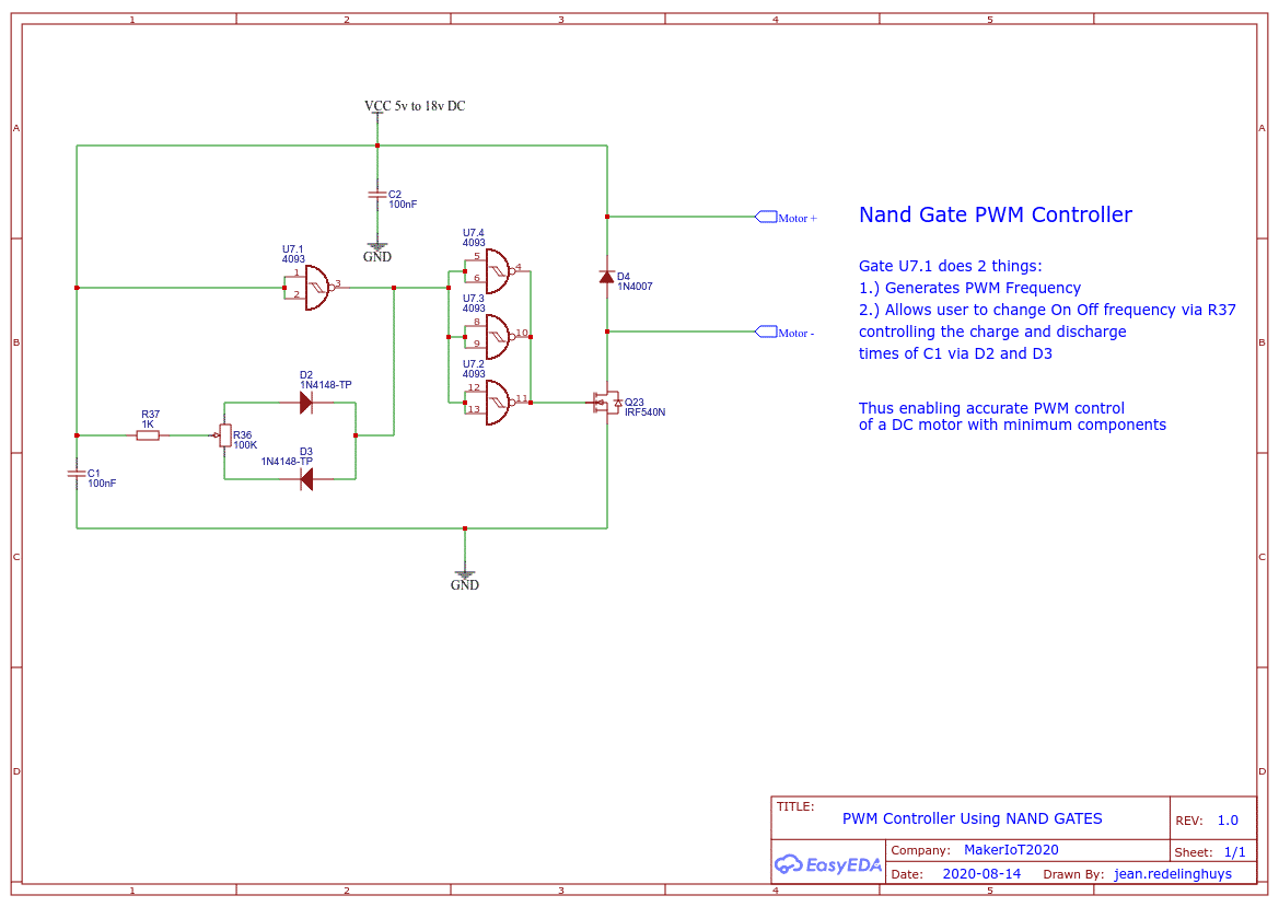
Our second circuit for today is a PWM motor controller, made using 4 NAND gates, a few resistors, capacitors, diodes, a mosfet and a variable resistor.
In this circuit, Nand Gate U7.1 generates the PWM frequency, as well as changes the on-off period of the PWM signal via R37, as the user turns the pot, the charge-discharge time of C1 is changed, thus altering the duty cycle of the signal.
This is thus an effective, low component way to do PWM motor control without a microcontroller.
Next week, I will introduce another two usefull NAND Gate based circuits for you to try out.